XXX International Conference on
Surface Modification Technologies (SMT30)
29TH JUNE - 1ST JULY, 2016, MILAN, ITALY
_____________________________
* Corresponding author. Tel.:+39 030 3715538 Fax. +39 030 3702 448 E-mail address: [email protected]
Laser texturing of a multilayer DLC from nano-liquid-diamond precursors
via microsecond laser pulses
A.Zivelonghi
a*, L.Giorleo
a, M.Gelfi
a, E.Ceretti
a, M.G. La Vecchia
aaUniversity of Brescia, Department of Mechanical and Industrial Engineering, Brescia, Italy
_________________________________________________________________________________________________________________________________
Abstract
Diamond Like Carbon (DLC) coatings have well known mechanical properties, including high hardness, chemical stability, optical transparency and biocompatibility. In addition they are frequently used in multilayer coating systems.
Laser surface texturing of DLC coatings can be a tailoring solution to optimize the coating functional parameters like roughness, wettability, wear, corrosion resistance, etc. Furthermore, compared to mechanical grinding, local laser removal could be a suitable technology for repairing locally damaged coated parts (i.e. worn surfaces, corroded surfaces, etc.)
In the present work, laser surface texturing and controlled laser removal of a multilayer DLC coating obained from nano-liquid-diamond precursors have been studied using a 8W Q-switched laser (λ=532 nm) with microsecond pulses. Textured ablation as well as full planar decoating are shown through proper adjustment of laser texturing parameters.
Keywords: laser ablation, laser etching, laser surface texturing, DLC
1. Introduction
Diamond like carbon (DLC) films are well known protective coatings due to excellent material properties like high hardness, chemical stability, optical transparency, dielectricity and biocompatibility (Bewilogua and Hofmann 2014,
Czyż et al. 2016
). DLC also possesses very favourable tribological properties which makes it an excellent low friction different engineering components (Kano 2006, Fontaine et al. 2008).Moreover, a number of studies have reported that the tribo-mechanical properties can be significantly improved by doping the DLC with various elements like Cr, Si, W, etc. (Chiu et al. 2005; Ban et al. 2002; Forsberg et al. 2013).
Laser ablation processing both of DLC coatings and related metallic substrates is a growing research field in material processing (Konov 2012,
Silva et al. 2013
). The process is based on laser ablation and is commonly referred in literature as laser surface texturing (LST). It has been recently proven, for instance, that laser texturing of pure DLC and DLC:Si is capable to further reduce the friction coefficient with tungsten carbide and alumina (Shum, Zhou, and Li 2013, Amanov et al. 2013).It should be pointed out that nowadays one often encounters a complex multilayer coating architecture, with interlayers to improve adhesion, particularly for automotive applications (Renman 2012).
In this context, decoting through laser ablation can be also of interest for those applications requiring repair of locally damaged coated parts. Controlling the ablation depth, however, is critical, particularly for multilayer coating systems. In this case, efficient decoating can only be achieved through controlled laser processing.
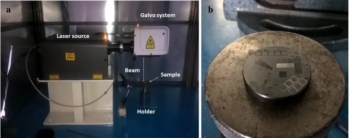
In the present work, laser removal of a 6.8 µm thick bilayer DLC + DLC:Cr coating system designed for tribological applications has been investigated. A 8W Q-switched laser source (λ=532 nm) in pulse mode was employed for the experiments (Fig.1).
Different decoating textures were obtained as a function of the different laser parameters. In order to control the decoating depth within the multilayer, energy dispersive spectroscopy (EDS) was employed in combination with scanning electron microscopy (SEM), optical measurements (OM) and calotest.
The paper strategy is as follows. The most influencing process parameters during decoating have been identified through controlled experiments on the laser input parameters. A first campaign on isolated laser spots using only one repetition loop aimed at showing the laser interaction effect on the DLC surface and identifying the ablation threshold. Then, in a futher campaign the effect of multiple loops and pulse overlap was investigated. An ON-OFF criterion was therefore established in order to select those configurations where the DLC coating was entirely removed. Within the selected modifications, full planar etching was finally shown.
Fig. 1. Left: experimental setup. Right: DLC sample.
2. Experimental Tests
The laser setup employed in the present work is shown in Fig. 1. A LEP Lee Laser (Nd:YVO4, 8 W q-switched, λ = 532 nm) was used in pulsed mode. The outgoing laser beam is collimated in a galvo system to impose a remote control in the x and y directions. The DLC sample with a diameter of 30 mm was fixed on a holder at a distance equal to the focal distance (160 mm) from the galvo head. All laser parameters are reported in Table 1. Average laser power was measured with a power meter. Pulse overlap percentage in x and y (Fig. 2b) were indirectly controlled by marking speed (v), laser frequency (f) and filling line gap (flg) according to the formulas reported in table 1. The flg is defined as the distance between two parallel lines of the laser path.
Table 1. Material and laser setup parameters used in the present study. Material
Coating type DLC+DLC:Cr on C40 Steel Deposition technique CAE-PVD + RF-PECVD Thickness - z 6.6 µm
Lased sample area 3 x 3 mm2
Laser Wavelength 532 nm Spot diameter - D 0.1 mm Focusing length 160mm Frequency - f 20 kHz Duty cycle - dc 20% Pulse duration – dt 10 µs Marking speed - v 200-2500 mm/s Max power - P 8 W
Number of loops - Nloop 1-30
Filling line gap - flg 0.01 - 0.1mm OLx = 1-flg/D 0-90% OLy = 1 -v/fD 0-90% Laser path parallel lines
Atmosphere air
DLC layers were deposited on EN 10083 C40 carbonsteel via different deposition techniques. Cathodic Arc Evaporation Physical Vapour Deposition (CAE-PVD) with solid targets was used for the CrC/Cr interlayer while the DLC top layer was obtained through Radio Frequency Plasma Enhanced Chemical Vapour Deposition (RF-PECVD) from Nano Liquid Diamond (NLD) precursors. The doped DLC:Cr layer was obtained through a hybrid process of both mentioned techniques. The resulting multilayer structure is described in Fig. 2. EDS as well as OM and Ra measurement were repeated on three different replicas of the same ablation spot.
Surface roughness Ra after laser etching was estimated with a profilometer (Mitutoyo SJ301).
Fig. 2. (a) Multilayer structure from calotest; (b) Laser path (blue lines) and overlapping parameters v/f and flg on the DLC surface.
2.2 On-off criterion for complete DLC etching
An ON-OFF criterion was set to determine the conditions of full removal along z of the bilayered DLC coating. First, EDS + SEM inspection were carried out to verify the lased surface composition and to obtain a proof of complete DLC removal. In fact, withstanding the difficulty in the quantitative evaluation from EDS, for the present case a large reduction of the percentage of Carbon (>70 wt.%) was considered a proof of the DLC + DLC:Cr removal and set as the required criterion. To confirm this, reference thicknesses of the multilayer were independently obtained through a calotest (CSM Instruments) and compared with depth measurements from OM on one reference lased configuration (#10).
2.2 Laser process parameters
Directly and indirectly controlled laser parameters are listed in table 2. Three levels of fluence (0.006, 0.1, 1 J/cm²) and four levels of loops Nloop (1, 10, 20 and 30) were firstly changed while maintaining the geometrical
configuration of well separated spots (configurations ID #1-12). This approach allowed to determine the full decoating conditions without the biasing effect of geometrical overlapping. The most effective laser fluence and the minimum number of loops satisfying the ON-OFF criterion were herewith identified. Finally, conditions for planar decoating were investigated varying the overlapping parameters OLx and OLy.
Table 2. Varied laser parameters and related configurations . Directly controlled parameters are marked with *. The ON/OFF output variable refers to complete DLC removal along z.
ID *Pavg [W] *flg [mm] *v [mm/s] *Nloop F [J/cm2]
OLx OLy ON/OFF
DLC removal #1 0.2 0.1 2500 1 0.006 0.00% 0.00% OFF #2 0.2 0.1 2500 10 0.006 0.00% 0.00% OFF #3 0.2 0.1 2500 20 0.006 0.00% 0.00% OFF #4 0.2 0.1 2500 30 0.006 0.00% 0.00% OFF #5 0.65 0.1 2500 1 0.1 0.00% 0.00% OFF #6 0.65 0.1 2500 10 0.1 0.00% 0.00% OFF #7 0.65 0.1 2500 20 0.1 0.00% 0.00% OFF #8 0.65 0.1 2500 30 0.1 0.00% 0.00% OFF #9 2.09 0.1 2500 1 1 0.00% 0.00% OFF #10 2.09 0.1 2500 10 1 0.00% 0.00% ON #11 2.09 0.1 2500 20 1 0.00% 0.00% ON #12 2.09 0.1 2500 30 1 0.00% 0.00% ON #13 2.09 0.01 2500 10 1 0.00% 90.00% ON #14 2.09 0.01 600 10 1 70.00% 90.00% ON #15 2.09 0.01 200 10 1 90.00% 90.00% ON 3. Results
3.1 Non-overlapping pulses (single spot)
Firstly, non-overlapping laser spots were studied at different fluence values. In this case Nloop was set equal to 1
(only one repetition) to isolate the effect of single laser pulses. A damage threshold of approximately 0.1 J/cm2 was found as evident in Fig. 3 where different laser spot fingerprints for increasing fluence values are shown.
5000 X 20000 X
Fig. 3 SEM image serie of single laser pulses on the DLC surface at different fluencies.
3.1 Non-overlapping pulses (single spot)
No surface modification was found at 0.006 J/cm² where the droplets (typical of the PECVD deposition process) are the same of the untreated sample. At 0.1 J/cm² the lased surface shows a change of topography characterized by a total removal of the surface droplet and the presence of a partial melting of the coating. Finally, in the transition from intermediate to high fluence (0.1 to 1 J/cm² ), a clear increase of the ablated spot area was observed. Hence the effect of multiple laser pulse repetitions on the isolated spots was investigated by varying the number of loops (Nloops). To roughly quantify this effect the percentage of the elements Carbon (C)
was monitored via SEM-EDS analysis for increasing values of Nloops and F. At a fluence value of 1 J/cm2, a
dramatic drop of the %C is observed when increasing Nloop from 1 to 10 (Fig. 4a). This variation - from about
80% to 10% - can be considered as a first clue of complete DLC + DLC:Cr removal in the z direction. This observation is further supported by SEM analyses, where the transition from DLC to the CrC interlayer is clearly visible (Fig. 4b). Moreover, etching depth estimations (Δz) with optical microscope finally confirmed a total removed coating thickness larger than 7 µm (±0.5µm due to instrumental accuracy limit). However, neither EDS
#1 F=0.006 J/cm2 #5 F=0.1 J/cm2 #9 F=1 J/cm2
a
b
c
d
e
f
nor OM can determine which of the sub-layers left between the CrC, the metallic Cr and the steel substrate due to uncertainty in the electron beam penetration depth and many other factors affecting the accuracy of EDS. Nonetheless, a clear saturation effect on the %C is observed for Nloops > 10 and F = 1 J/cm2 (Fig 4c) once the
DLC layers are completely removed and further pulses impinge on the CrC/Cr interlayer. This saturation effect is certainly related to an increase in ablation threshold once the ablated surface reached the CrC/Cr interlayer. Concerning the transition depth from DLC:Cr to non-DLC layers, results are in good agreement with calotest. This can be stated in view of uncertainty from calotest and optical measurement (±0.5µm) as well as of layer thickness irregularity caused during deposition.
Fig. 4. (a) %C from EDS analysis on the ablated surface at different values of Nloopsand F; (b) SEM image of the reference lased surface
#10 showing full DLC removal at the ablation spot center; (c) Removed thickness estimated with optical microscope compared to results from calotest.
3.2 Overlapping pulses
Among the different configurations which satisfied the condition of complete DLC removal along the z-axis, the parameters of marking speed (v) and filling line gap (flg) were further varied to obtain different overlapping conditions in the in-plane directions (x and y of Fig. 2b). These configurations are the #13-15 in table 1. In Fig. 5 three of the resulting textures are shown while fixing Nloop = 10 and flg = 0.01 mm. Parallel vertical
lines were obtained at v = 2500 mm/s and 600 mm/s (Fig. 5a,b). The resulting decoating channels have a width of about 70 µm in the first case with pronounced residual roughness of the engraved CrC/Cr layers. At 600 mm/s thinner channels (ca. 30 µm width) are observed as an effect of increased overlapping of the laser spot along x. Although the theoretical overlap was 70% (config. #14 in Tab.1), residual borders of partially ablated DLC:Cr are still evident due to non-uniform energy distribution of the laser spot. Moreover, some debris are evident on the channel surface. Finally, planar uniform etching was obtained at v = 200 mm/s and flg = 0.01 mm (Fig. 5e,f). In this case the lased surface appears very clean with a measured residual roughness of about 0.2 µm. EDS analysis on this surface (Fig. 6) also confirmed a very low value of Oxygen (~3 wt.%) upon which one envisages
c
the possibility of DLC redeposition after proper surface handling. However, future investigations are needed including the evaluation of mechanical properties of the redeposited coating.
5000 X 15000 X
Fig. 5 Different surface textures showing full laser etching of DLC + DLC:Cr along z.
Table 3. EDS spectrum of configuration #15 .Scanned area 60 * 50 µm(Fig. 5f).
Spectrum wt.% C O Cr Fe Total Spectrum 1 2.44 3.61 8.80 85.16 100.00 Spectrum 2 3.17 2.74 10.2 83.88 100.00 Mean 2.80 3.17 9.5 84.52 100.00 Std. Dev. 0.52 0.30 0.98 0.91 #13 v=2500 mm/s #14 v=600 mm/s #15 v=200 mm/s
a
b
c
d
e
f
4.
ConclusionsIn the present paper controlled laser ablation of a multilayer DLC coating has been studied. This technique is able to efficiently and selectively etch micrometric DLC layers giving rise to different surface textures. The present campaign aimed at showing the influence of laser fluence, loops number, and overlapping parameters on the final texture. A Nd:YVO4 laser source, with wavelength equal to 532 nm and average pulse power up to 2 W was employed in the experiments. Results highlight that uniform decoating of DLC with good surface quality of the rest surface can be achieved. This was shown at a conveniently high fluence (fairly above the ablation threshold) and at a conveniently low marking speed.
Acknowledgements
The authors wish to thank Protec Surface Technologies srl for providing the DLC samples. A.Z. express gratitude to Dr. L.Montesano and Dr. C.Pietrogalli for experimental support.
References
Amanov, Auezhan, Tsukasa Watabe, Ryo Tsuboi, and Shinya Sasaki. 2013. “Improvement in the Tribological Characteristics of Si-DLC Coating by Laser Surface Texturing under Oil-Lubricated Point Contacts at Various Temperatures.” Surface and Coatings Technology 232 (October): 549–60.
Ban, Masahito, Makoto Ryoji, Sadao Fujii, and Junzo Fujioka. 2002. “Tribological Characteristics of Si-Containing Diamond-like Carbon Films under Oil-Lubrication.” Wear: An International Journal on the Science and Technology of Friction Lubrication and Wear 253 (3). Elsevier: 331–38.
Bewilogua, Klaus, and Dieter Hofmann. 2014. “History of Diamond-like Carbon Films—from First Experiments to Worldwide Applications.” Surface and Coatings Technology 242. Elsevier: 214–25.
Chiu, Ming-Chieh, Wen-Pin Hsieh, Wei-Yu Ho, Da-Yung Wang, and Fuh-Sheng Shieu. 2005. “Thermal Stability of Cr-Doped Diamond-like Carbon Films Synthesized by Cathodic Arc Evaporation.” Thin Solid Films 476 (2). Elsevier: 258–63.
Czyż, Krzysztof, Czyż Krzysztof, Marczak Jan, Major Roman, Mzyk Aldona, Rycyk Antoni, Sarzyński Antoni, and Strzelec Marek. 2016. “Selected Laser Methods for Surface Structuring of Biocompatible Diamond-like Carbon Layers.” Diamond and Related Materials 67: 26–40.
Fontaine, J., C. Donnet, and A. Erdemir. "Fundamentals of the Tribology of DLC Coatings." In Tribology of Diamond-Like Carbon Films, pp. 139-154. Springer US, 2008.
Forsberg, Peter, Fredrik Gustavsson, Viktor Renman, André Hieke, and Staffan Jacobson. 2013. “Performance of DLC Coatings in Heated Commercial Engine Oils.” Wear: An International Journal on the Science and Technology of Friction Lubrication and Wear 304 (1). Elsevier: 211–22.
Kano, Makoto. "DLC coating technology applied to sliding parts of automotive engine." New Diamond and Frontier Carbon Technology 16, no. 4 (2006): 201-210.
Konov, V. I. 2012. “Laser in Micro and Nanoprocessing of Diamond Materials.” Laser & Photonics Reviews 6 (6). WILEY-VCH Verlag: 739–66.
Renman, Viktor. "Tribological testing of DLC coatings for automotive applications." (2012).
Shum, P. W., Z. F. Zhou, and K. Y. Li. 2013. “Investigation of the Tribological Properties of the Different Textured DLC Coatings under Reciprocating Lubricated Conditions.” Tribology International 65 (September): 259–64.
Silva, William de Melo, William de Melo Silva, José Rubens Gonçalves Carneiro, and Vladimir Jesus Trava-Airoldi. 2013. “XPS, XRD and Laser Raman Analysis of Surface Modified of 6150 Steel Substrates for the Deposition of Thick and Adherent Diamond-like Carbon Coatings.” Materials Research 16 (3): 603–8.