2017 Publication Year
2020-07-27T08:07:46Z Acceptance in OA@INAF
The afocal telescope of the ESA ARIEL mission: analysis of the layout Title
Da Deppo, Vania; Middleton, Kevin; FOCARDI, MAURO; MORGANTE, GIANLUCA; Corso, Alain Jody; et al.
Authors 10.1117/12.2273197 DOI http://hdl.handle.net/20.500.12386/26636 Handle PROCEEDINGS OF SPIE Series 10398 Number
PROCEEDINGS OF SPIE
SPIEDigitalLibrary.org/conference-proceedings-of-spie
The afocal telescope of the ESA
ARIEL mission: analysis of the layout
Vania Da Deppo
Kevin Middleton
Mauro Focardi
Gianluca Morgante
Alain Jody Corso
Emanuele Pace
Riccardo Claudi
Giuseppina Micela
The afocal telescope of the ESA ARIEL mission: analysis of the layout
Vania Da Deppo*
a,b, Kevin Middleton
c, Mauro Focardi
d, Gianluca Morgante
e, Alain Jody Corso
a,
Emanuele Pace
f, Riccardo Claudi
b, Giuseppina Micela
ga
CNR-Instituto di Fotonica e Nanotecnologie, Padova, Via Trasea 7, 35131 Padova, Italy
bINAF-Osservatorio Astronomico di Padova, Vicolo dell’Osservatorio 5, 35122 Padova, Italy
c
RAL Space-STFC Rutherford Appleton Laboratory, Harwell Campus, Didcot OX11 0QX, UK
d
INAF-Osservatorio Astrofisico di Arcetri, Largo E. Fermi 5, 50125 Firenze, Italy
eINAF-IASF Bologna, Area della Ricerca, Via Piero Gobetti 101, 40129 Bologna, Italy
fDip. di Fisica ed Astronomia-Università degli Studi di Firenze, Largo E. Fermi 2, 50125 Firenze,
Italy
g
INAF-Osservatorio Astronomico di Palermo, Piazza del Parlamento 1, 90134 Palermo, Italy
ABSTRACT
ARIEL (Atmospheric Remote-sensing Infrared Exoplanet Large-survey) is one of the three present candidates as an M4 ESA mission to be launched in 2026. During its foreseen 3.5 years operation, it will observe spectroscopically in the infrared a large population of known transiting planets in the neighborhood of the Solar System. The aim is to enable a deep understanding of the physics and chemistry of these exoplanets.
ARIEL is based on a 1-m class telescope ahead of a suite of instruments: two spectrometer channels covering the band 1.95 to 7.8 µm and four photometric channels (two wide and two narrow band) in the range 0.5 to 1.9 µm.
The ARIEL optical design is conceived as a fore-module common afocal telescope that will feed the spectrometer and photometric channels. The telescope optical design is based on an eccentric pupil two-mirror classic Cassegrain configuration coupled to a tertiary paraboloidal mirror.
The temperature of the primary mirror (M1) will be monitored and finely tuned by means of an active thermal control system based on thermistors and heaters. They will be switched on and off to maintain the M1 temperature within ±1 K thanks to a proportional–integral–derivative (PID) controller implemented within the Telescope Control Unit (TCU), a Payload electronics subsystem mainly in charge of the active thermal control of the two detectors owning to the spectrometer. TCU will collect the housekeeping data of the controlled subsystems and will forward them to the spacecraft (S/C) by means of the Instrument Control Unit (ICU), the main Payload’s electronic Unit linked to the S/C On Board Computer (OBC).
Keywords: space instrumentation, telescope, optical design, exoplanetary science, thermal control, ICU
1. INTRODUCTION
ARIEL is one of the M4 proposed missions in the framework of the ESA Cosmic Vision program [1]. This mission is conceived to study the atmospheres of exoplanets orbiting close to nearby stars. The aim is to measure the atmospheric composition and structure of hundreds of exoplanet atmospheres, using spectroscopy in the infrared wavelengths. This will allow the exploration and sounding of the nature of the exoplanets’ atmospheres, to collect information about the planets’ interiors and to study the key factors affecting the formation and evolution of planetary systems.
ARIEL is designed as a survey mission for transit and eclipse spectroscopy. During its 3.5-year scientific mission lifetime in L2 orbit, it will provide spectroscopic information on the atmospheres of a large and well-defined sample of exoplanets (about 1000 in the present scientific scenario) allowing the compositions, temperature (profile), size and variability to be determined at a level never previously attempted [2]. It will measure the reflected/emitted/transmitted spectra of these exoplanetary atmospheres over the visible to the thermal IR wavelength range. Planets under study will extend from gas giants, i.e. Jupiter-like planets, to Neptune-like and super-Earths [3].
*[email protected]; phone +39-049 9815639; fax +39-049 774627
UV/Optical/IR Space Telescopes and Instruments: Innovative Technologies and Concepts VIII edited by Howard A. MacEwen, James B. Breckinridge, Proc. of SPIE Vol. 10398, 1039812
© 2017 SPIE · CCC code: 0277-786X/17/$18 · doi: 10.1117/12.2273197
Proc. of SPIE Vol. 10398 1039812-1
Optical bench with focal plane instruments and
radiator Primary mirror (M1)
Telescope baffle Secondary mirror (M2) with refocusing mechanism Xsc - Service Module (SVM) FGS) Opt, Modt Dichp
Optical bench & Metering Structure
uems
'Port eture
V-Groove Radiators
Thanks to the knowledge of the planetary ephemerides of the selected targets, ARIEL will be able to differentiate the signals coming from the planet and the host star. This enables the measurement of atmospheric signals from the planet at levels of at least 10-4 relative to the star. Given the bright nature of targets, the adoption of more sophisticated
techniques, such as phase curve analysis and eclipse mapping, will provide a deeper insight into the nature of their atmospheres. This requires a payload with broad instantaneous wavelength coverage, to detect many molecular species, probe the thermal structure, identify clouds and monitor the stellar activity as well. To guarantee the required photometric accuracy and precision, a specifically designed stable payload and satellite platform are needed.
Transit spectroscopy means that no angular resolution is required and detailed performance studies, performed by the ARIEL Consortium, show that a telescope collecting area of 0.64 m2 is sufficient to achieve the necessary observations
on all the ARIEL targets within the mission lifetime.
ARIEL will carry a telescope unit feeding a collimated beam into two separate modules. A combined Fine Guidance System(FGS)/VIS-Photometer/NIR-Spectrometer that contains three photometric channels in the wavelength range between 0.50 μm and 1.2 μm to monitor the photometric stability of the target stars. Two of these channels will also be used as a prime/redundant system for providing guidance and closed-loop control to the high stability pointing Attitude and Orbit Control System (AOCS) of the S/C. Integrated in this same module is a further low-resolution (R=~10) NIR spectrometer channel in the 1.2–1.95 μm waveband. This first combined module is often simply referred to as the FGS. The second module, acting as the main instrument, is the ARIEL IR Spectrometer (AIRS), providing variable resolving power in the range 30–180 for a waveband between 1.95 μm and 7.8 μm.
The payload is passively cooled to ~50 K by isolation from the S/C bus via a series of V-Groove radiators. The AIRS detectors are the only items that require active cooling to <42 K via an active Ne-based JT cooler.
ARIEL is highly complementary to other international facilities (such as TESS [4], to be launched in 2018) and will build on the success of ESA exoplanet missions such as Cheops [5] and PLATO [6], which will provide an optimized target list prior to launch.
2. SPACECRAFT AND SCIENCE PAYLOAD
2.1 Spacecraft architecture
A “horizontal” configuration, with respect to the Service Module (SVM) cylinder, has been adopted as baseline for the spacecraft architecture (see Figure 1a). The X axis of the ARIEL mechanical reference system corresponds with the telescope mirrors optical axis, the Z axis is the launch vehicle symmetry axis (“vertical”) and Y axis completes the right-handed set.
(a) (b)
Figure 1. In (a) schematics of ARIEL spacecraft baseline configuration: main components and S/C reference system are highlighted; the red cover shows the minimum allowable volume with respect to the Sun vector. In (b) ARIEL baseline payload block diagram
architecture.
The spacecraft (S/C) can be considered as composed of a cold Payload Module (PLM), containing the telescope and the instruments with their thermo-mechanical hardware, and a warm Service Module (SVM) that includes all the mission
Proc. of SPIE Vol. 10398 1039812-2
C > M5 and calibration source FGS Module / AIRS -CHO Input slit M4
supporting systems together with the PLM and cryogenic control units [7]. The PLM will interface to the SVM via a set of thermally isolating support struts, or bipods, and will be radiatively shielded from the SVM and the solar input loads by a set of 3 V-Grooves (VGs). A block diagram of the overall payload architecture, including the subsystems, is shown in Figure 1b.
The Sun is located below the platform (i.e. –ZS/C). The V-Grooves and volumes are designed to accommodate a ±6°
angle and a ±30° angle clearance respectively around the X axis and the Y axis with respect to the Sun vector. 2.2 Payload module
The spacecraft carries a single dedicated payload conceived to achieve the ARIEL primary science objectives. The ARIEL cold PLM consists of an integrated suite of telescope, spectrometers and FGS/photometers along with the necessary supporting hardware and services (such as optical bench, cryogenic harnessing, thermal isolation structures, active thermal stabilization control, i.e. heaters and thermistors, etc.).
The ARIEL telescope consists of three mirrors (M1, M2 and M3) having optical power plus a plane mirror (M4) used to redirect the collimated beam towards the optical bench (OB) located on the back of M1 (see Figure 2a and Figure 3). The secondary mirror is located at the end of a metering structure (beam) departing from the OB and it will be equipped, as a baseline, with a refocusing and tip/tilt mechanism. There will be also an eccentric baffle around M1, internal vanes between M1 and M2, M2 and M3, field and Lyot stops to control and limit both the out-of-field and in-field scattered straylight.
(a) (b)
Figure 2. In (a) ARIEL telescope mechanical layout. In (b) mechanical design of the OB with highlighted the optical path to the FGS and AIRS modules; in the inset there is a zoom on the common optics region.
The primary science payload is the spectrometer, whose scientific observations are supported by the FGS/photometers, which is monitoring the photometric stability of the target and allowing, at the same time, the target to be properly pointed. Both the spectrometer and FGS modules will be mounted on the common OB (see Figure 2b).
2.2.1 FGS and its objectives
The FGS main task is to ensure the correct pointing of the satellite, in order to guarantee that the target star is well centred on the spectrometer slit during all the observation sessions. It will also provide high precision astrometry, photometry and spectro-photometry of the target for complementary science. In particular, the data from the FGS will be used for de-trending and data analysis on ground. The sensor uses star light coming through the optical path of the telescope to determine the changes in the line of sight of the ARIEL instrument. The attitude measurement is then merged with the information from the star trackers, and used as input for the control loop stabilizing the spacecraft through high performance gyros.
To meet the goals for guiding and photometry, four spectral bands are defined: • FGS 1: 0.8–1.0 µm,
• FGS 2: 1.05–1.2 µm, • VIS-Phot: 0.50–0.55 µm,
• NIR-Spec: 1.25–1.90 µm including a prism element with low spectral resolution greater than 10.
The spectral bands are selected from the incoming light using dichroic filters. The information from all the channels is used as a stellar monitor and to provide photometric information to constrain the VIS/NIR portion of the exoplanet
Proc. of SPIE Vol. 10398 1039812-3
spectra. The instrument has two detectors: one is shared by the FGS1 and VIS-Phot channels and the other one by the FGS2 and NIR-Spec channels.
2.2.2 ARIEL IR Spectrometer (AIRS)
AIRS is a broadband, low-resolution NIR and MIR spectrometer operating between 1.95 μm and 7.8 μm. This module can be properly split into multiple channels avoiding loosing wavelengths with key spectral features.
The baseline design foresees two spectrometers with independent optical channels and detectors: the first one (CH0) covering the shorter waveband (1.95–3.9 µm), the second (CH1) the longer waveband (3.9–7.8 µm). As dispersive element, prisms have been considered in the present design [8].
The spectrometer detectors are expected to require active cooling managed by a thermal control system (TCS) operated by the TCU, providing a nominal operating temperature of ~36 K, to reach both the requirement and goal performance with the chosen baseline sensors [9].
3. TELESCOPE OPTICAL DESIGN
3.1 Telescope design requirements
The telescope has been designed in order to provide the optical requirements reported in Table 1. The requirement on the collecting area of at least 0.6 m2 implies an entrance pupil of the order of 1 m in diameter. The collecting area is
related with the minimum intensity (magnitude) of the observable targets.
The design performance is driven by the requirement that the final as-built quality of the telescope system has to be diffraction limited at 3 µm over a FoV of 30", i.e. equivalent to an RMS wavefront error (WFE) of 220 nm.
To guarantee the required throughput without increasing the size of the primary mirror, that is the entrance pupil of the telescope, the optical design has to be unobscured. The unobstructed solution also assures the energy in the PSF is primarily contained inside the first Airy disk and not spread towards the secondary rings.
Table 1. Summary of the telescope optical requirements.
Parameter Value
Collecting area >0.6 m2
FoV 30" with diffraction limited performance
41" with optical quality TBD allowing FGS centroiding 50" unvignetted
WFE Diffraction limited @ 3 μm Wavelength range 0.55–8 μm
Throughput Minimum >0.78
Average >0.82 Output beam dimension 20 mm x 13.3 mm
The wavelength coverage and the global FoV of the telescope are determined by the requirements on the instruments following the telescope, i.e. the FGS and the AIRS [10].
3.2 Telescope design characteristics
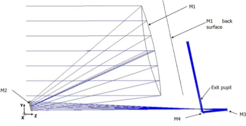
The baseline telescope design is an afocal unobscured eccentric pupil Cassegrain telescope (M1 and M2) with a recollimating off-axis parabolic tertiary mirror (M3). All the mirrors share the same optical axis. An M4 plane mirror is redirecting the exiting beam parallel to the back of M1 where the OB is located and the instrument will be mounted (see Figure 3).
The telescope is accommodated horizontally with its optical axis (Z) along the S/C X axis. The centre of the FoV of the telescope is inclined of 0.1° in the YZ plane with respect to the optical axis of the telescope defined by the mirrors common optical axis.
Proc. of SPIE Vol. 10398 1039812-4
M2
M4
Figure 3. Scale drawing of the telescope – view in Y-Z plane.
The system aperture stop/entrance aperture is located at the M1 surface. The M1 aperture is an ellipse with major/minor axes dimensions of 1100 mm x 730 mm. The complete characteristics of the optical design are summarized in Table 2a, while in Table 2b the telescope mirror parameters (radius of curvature, conic constant, off-axis, etc.) are described.
Table 2. (a) Summary of the telescope optical design characteristics. (b) Mirrors parameters description.
(a) (b) Optical element M1 M2 M3 R (mm) -2319.5 -239.0 -491.5 k -1 -1.4 -1 Off-axis (mm) (y direction) 500 50 20 Clear Aperture Radius (mm) Elliptical, 550 (x) by 365 (y) Elliptical, 56 (x) by 40 (y) Elliptical, 15 (x) by 11 (y)
Type Concave mirror Convex mirror Concave mirror
3.3 Telescope optical performance
The raytracing analysis and design optimization have been done by means of the raytracing software Zemax®. To assess the quality of the telescope and determine the optical performance, since the telescope is afocal, the spot diagrams can be given using an ideal focusing paraxial lens with a defined focal length, or using the afocal image space option appropriate for systems with collimated output. Note that the spot diagrams obtained with this second method have their size expressed in milliradians.
The nominal diffraction PSF at 3 µm wavelength has an Airy radius respectively of 0.2 mrad and 0.29 mrad in the X and Y directions. A picture of the expected theoretical PSF is depicted in Figure 4a; in Figure 4b for comparison the spot diagram all over the 50" unobstructed telescope FoV are drawn and compared with a box of 0.4 mrad size, so to show that telescope design is diffraction limited at the 3 µm primary wavelength.
The telescope RMS wavefront error is always less than 26 nm over the 30" nominal telescope FoV (see Figure 5); this value is well below the telescope diffraction limit at 3 µm, i.e. 220 nm.
Parameter Values
Optical concept Afocal design. Eccentric pupil Cassegrain telescope plus
off-axis paraboloidal mirror and folding. Focal length 14.17 m FoV centre 0.1° - Off-axis YZ plane Pupil size Ellipse with major axis
1.1 m x 0.73 m Focal ratio @
intermediate
telescope focus 13 (x)/19.4 (y) Angular
magnification -55
Proc. of SPIE Vol. 10398 1039812-5
(a) (b) Figure 4. In (a) PSF calculated at the telescope FoV centre for a wavelength of 3 µm depicted over a 1 mrad square box. In (b) Spot
Diagrams in the afocal space; the scale (box) is 0.4 mrad.
-30 -20 -10 0 10 20 30 20 25 30 35 R M S _ wave fr ont_ e r (nm) FoV(") (a) (b)
Figure 5. In (a) RMS wavefront error field map calculated for the 3 µm wavelength over the 30" nominal telescope FoV. Units are λ. In (b) cross section along the Y direction of the RMS wavefront error expressed in nm; in the X direction the wavefront error is
constant.
To assess the final performance of the as-built telescope and its variation during the operation in flight, a tolerance analysis has been done [11] [12]. The tolerance analysis has taken into account the different parts of the realization and life of the instrument:
1. Manufacturing, integration and alignment. 2. Launch loads and change from 1 g to 0 g.
3. Cooldown in orbit from ambient temperature to the nominal (about 50 K) operating temperature.
4. Stability in flight: short term (over 1 single exposure to about 10 hours) and long term (over the whole mission operative lifetime).
The results show that the telescope, thermally stable after cooldown and refocused via M2 mechanism, will have a wavefront error of the order of the required 220 nm RMS. The total RMS wavefront error in flight, including the stability, will be within 250 nm, which is perfectly suitable to achieve the scientific purpose of the instrument.
4. TELESCOPE THERMAL CONTROL
The telescope is passively cooled to ≤70 K and its thermal control is based on a passive/active approach. A high efficiency thermal shielding system (see Figure 6) based on a multiple radiators configuration can provide stable temperature stages down to 50-60 K in the L2 orbit environment.
0.0000 0.1000 0.2000 0.3000 0.4000 0.5000 0.6000 0.7000 0.8000 0.9000 1.0000 Huygens PSF
Surface IMA: IMAGE SPACE
0.40 OBJ: 0.0000, 0.0070 (deg) IMA: 0.0000, 0.0000 rad OBJ: 0.0000, 0.0057 (deg) IMA: 0.0000, 0.0013 rad OBJ: 0.0000, 0.0042 (deg) IMA: 0.0000, 0.0028 rad OBJ: 0.0000, 0.0000 (deg) IMA: 0.0000, 0.0070 rad OBJ: 0.0000, -0.0042 (deg) IMA: 0.0000, 0.0112 rad OBJ: 0.0000, -0.0057 (deg) IMA: -0.0000, 0.0127 rad OBJ: 0.0000, -0.0070 (deg) IMA: -0.0000, 0.0140 rad OBJ: -0.0070, 0.0000 (deg) IMA: 0.0070, 0.0070 rad OBJ: -0.0057, 0.0000 (deg) IMA: 0.0057, 0.0070 rad OBJ: -0.0042, 0.0000 (deg) IMA: 0.0042, 0.0070 rad 3.0000 Spot Diagram 6.51E-003 6.70E-003 6.89E-003 7.09E-003 7.28E-003 7.47E-003 7.66E-003 7.85E-003 8.04E-003 8.24E-003 8.43E-003
RMS Wavefront Field Map
Proc. of SPIE Vol. 10398 1039812-6
COLD 4 to Telescope Baffle Space M1 tnstrument E 4EE lmf AIRSBOx
gz,
(t tot Space aslxgPlwas M2A
Insulating Strut < 55K Conductive Strut Thermal Strap Harness TIF3 to VGroove3 A L TIF2 to VGroove2 11 TIFI to VGroove1-TIFO to SVM SVMWARM
T Stages Top SVM MLI ElectronicsThe telescope baffle provides a large radiator area with a good view to deep space; this provides sufficient radiative cooling to dump the parasitic loads from the PLM support struts, cryoharnesses and radiative load from the final VG. Temperature control of the mirrors is achieved by partial thermal decoupling from PLM units: each mirror is mounted on its supporting structure by insulating struts with a total conductance of less than 0.1 W/K.
Figure 6. PLM thermal architecture scheme.
This configuration will help in filtering out all potential instabilities with periods of the order of 10–100 s originated in the PLM and longer than the expected single exposure times.
For the primary mirror, the high thermal capacitance, due to its mass, will allow a higher level of passive filtering, damping instabilities at lower frequencies, i.e. with periods of the order of few hours. The slower fluctuations, with periods of the order of several hours or longer, that could be transmitted to the optics will be smoothed by the active control system based on a PID type feed-back loop.
The telescope will also incorporate contamination control heaters on the M1 and M2 mirrors and on the PLM optical bench. These heaters will be active during the early orbit operations to ensure that the sensitive optical surfaces remain warmer than the support structure through the critical parts of cooldown. A temperature delta of ~40 K will be maintained between the baffle, which will act as a contamination getter for water and other contaminants being off-gassed by the PLM, and the optical surfaces. An initial calculation of the power required to maintain this temperature gradient shows that approximately 100 W of heater power is required during this phase. This would hold the sensitive surfaces at 200 K while the baffle cools below 160 K where the H2O will freeze out.
5. TELESCOPE CONTROL UNIT
The ARIEL Instrument Control Unit (ICU) [13] is the main electronic subsystem designed for scientific data pre-processing and to implement the commanding and control of the AIRS Spectrometer. The ICU is interfaced on one side with the instrument and on the other side, i.e. S/C side, with the Data Management System (DMS) and the Power Conditioning and Distribution Unit (PCDU), both belonging to the hosting platform.
The DMS is composed of the On-Board Computer (OBC) and the Solid State Mass Memory (SSMM) operating as the main buffering memory for scientific data and HK telemetries before sending them to ground. For this reason, the ICU internal memories are basically conceived and designed for temporary local buffering and to support a reduced data handling as the AIRS scientific data, once properly pre-processed, are delivered to the SSMM.
Proc. of SPIE Vol. 10398 1039812-7
This charact architectures detectors by As the ICU i by means of called Detect The Telescop volume is loc board called mirror mecha In this paper various elem telescope; its discussed. The theoretic shown. The mirror follow A preliminar cooled at an The optical tuned/stabiliz Finally, the electrical sub teristic is exp s (baseline an means of thei is hosted by a cryogenic har tor Control Un pe Control Un cated in an in Thermal Sta anism (M2M) r an introducti ments composin s afocal layou cal performan chosen config wed by a plane ry study on th operating tem bench opera zed mainly by end-to-end de bsystems, hav ploited to sim nd alternative) ir customized warm electro rness. The ICU nit (DCU), as nit (TCU) is ndependent bo abilizer (for th ) drivers and th ion on the AR ng the spacecr ut solution ha nce, i.e. spot guration is an e folding mirr he passive/acti mperature of ab ating tempera y means of the etection and d e been describ mplify the un ) designed at Cold Front-En onic box, it wi U subsystem a shown in Fig indeed consid ox, with stacke he primary m
he needed pow
Figure 7.
On-6. C
RIEL mission raft and the pa as been descr diagrams, PS un-obscured ror. ive thermal co bout 50 K. atures, as we e thermal cont data processin bed. nit electrical t this stage to nd Electronic ill be located i acting as inter gure 7. dered an ICU ed drawers to mirror Thermal wer section to board electroni CONCLUSIO design and g ayload. A fun ribed and the SF and wavef eccentric pup ontrol of the i ell as those trol subsystem ng system, up design, savin o be interfac s (CFEE), ope inside the S/C rface to the cry
slave subsys the unit main l Control Sys o properly feed
ics architecture.
ONS
oals has been damental elem different requ front error, of pil Cassegrain instrument ha of some sub m working in f p to the Instru ng mass and ed respective erating at cryo C SVM and co yogenic harne tem and for i n box. The TC stem) & IR C d its subsystem . n given togeth ment of the pa uirements and f the baseline n plus a collim as been given. bsystems, wi feedback close ument Control power, for b ely to US det ogenic temper onnected to th ess is a warm its complexity CU will host t Calibrator (TS ms.
her with a desc ayload is the fr d characterist e telescope lay mating off-axi . The telescop ill be monito ed-loop. l Unit (ICU)
both the ICU tectors or EU ratures.
e AIRS CFEE FEE (WFEE) y and required
the main logic SIRC), the M2
cription of the ront collecting tics have been yout has been s paraboloida pe is passively ored and fine and S/C main U U E ), d c 2 e g n n al y e n
Proc. of SPIE Vol. 10398 1039812-8
ACKNOWLEDGMENTS
This activity has been realized under the Agenzia Spaziale Italiana (ASI) contract to the Istituto Nazionale di Astrofisica (INAF) (ARIEL 2015-038-R.0) and with the support of Leonardo S.p.A. (Campi di Bisenzio (FI) – Italy).
The authors gratefully acknowledge the support provided by the ESA ARIEL Study Team, the University College of London (UCL), leading the project, and the Rutherford Appleton Laboratory (RAL Space) managers and engineers.
REFERENCES
[1] Puig, L., Pilbratt, G. L., Heske, A., Escudero Sanz, I., and Crouze, P.-E., "ESA M4 mission candidate ARIEL", Proc. SPIE 9904, 99041W (2016).
[2] Tinetti, G., et al., "The science of ARIEL (Atmospheric Remote-sensing Infrared Exoplanet Large-survey)", Proc. SPIE 9904, 99041X (2016).
[3] ARIEL SST, "ARIEL Science Requirements Document", ESA-ARIEL-EST-SCI-RS-001, (2015).
[4] Ricker, G. R., et al., "The Transiting Exoplanet Survey Satellite (TESS): discovering exoplanets in the solar neighborhood", to be published in Proc. SPIE 9904, 9904-2B (2016).
[5] Fortier, A., et al., "CHEOPS: a space telescope for ultra-high precision photometry of exoplanet transits", Proc. SPIE 9143, 91432J (2014).
[6] Ragazzoni, R., et al., "PLATO: a multiple telescope spacecraft for exo-planets hunting", Proc. SPIE 9904, 990428 (2016).
[7] Eccleston, P., et al., "An integrated payload design for the Atmospheric Remote-sensing Infrared Exoplanet Large-survey (ARIEL)", Proc. SPIE 9904, 990433 (2016).
[8] Amiaux, J., "AIRS optical design trade-off analysis", ARIEL-CEA-INST-DD-001, (2016).
[9] Focardi, M., et al., "The Atmospheric Remote-sensing Infrared Exoplanets Large-survey (ARIEL) payload electronic subsystems", Proc. SPIE 9904, 990436 (2016).
[10] Da Deppo, V., et al, "Design of an afocal telescope for the ARIEL mission", Proc. SPIE 9904, 990434 (2016). [11] Da Deppo, V., et al., "The afocal telescope optical design and tolerance analysis for the ESA ARIEL Mission",
OSA’s Optical Design and Fabrication Congress, Denver (USA), 9-13 July 2017 (2017).
[12] Sierra Roig, C., et al., "The ARIEL ESA mission on-board metrology", IEEE Workshop on Aerospace Metrology, Padova (Italy), 21-23 June 2017 (2017).
[13] Focardi, M., et al., "The ARIEL Instrument Control Unit design for the M4 Mission Selection Review of the ESA’s Cosmic Vision Program", to be published in Special Issue on ARIEL, Exp. Astron. (2017).
Proc. of SPIE Vol. 10398 1039812-9