DEI - Dipartimento di Ingegneria dell’Energia Elettrica e dell’Informazione
Dottorato di Ricerca in Ingegneria Elettronica, delle Telecomunicazioni e Tecnologie dell’Informazione
XXVIII Ciclo
Settore Concorsuale: 09/F2 - Telecomunicazioni Settore Scientifico Disciplinare: ING-INF/03
Heterogeneous Networks for the IoT and Machine Type
Communications
Tesi di:
Melchiorre Danilo Abrignani
Coordinatore:
Chiar.mo Prof. Ing. Alessandro Vanelli-Coralli
Relatori:
Chiar.mo Prof. Ing. Roberto Verdone
Table of Contents iii
Abstract vii
List of Acronyms ix
List of Figures xxi
List of Tables xxv
Introduction 1
Motivation . . . 1
Context of the Thesis: Newcom♯ . . . 2
EuWIn . . . 3
Structure of the Thesis and Approach . . . 4
1 IoT and M2M 7 1.1 IoT Applications . . . 8
1.1.1 Issues and challenges . . . 10
1.2 IoT scenarios - Heterogeneous networks . . . 12
1.3 Standardization players . . . 12
1.3.1 3rd Generation Partnership Project (3GPP) . . . 12
1.3.2 European Telecommunications Standards Institute (ETSI) . . 13
1.3.4 Comit´e Europen de Normalisation - European Commitee for Standardization (CEN)/Comit´e Europ´een de Normalisation
´
Electrotechnique - European Committee for Electrotechnical
Standardization (CENELEC) . . . 14
1.3.5 Institute of Electrical and Electronics Engineers (IEEE) . . . . 14
1.3.6 Internet Engineering Task Force (IETF) . . . 14
1.3.7 International Telecommunication Union Telecommunication Standardization Bureau (ITU-T) . . . 15
1.4 M2M Traffic Models . . . 15
1.5 Conclusions . . . 17
2 IoT short range solutions 19 2.1 Standards . . . 20 2.1.1 IEEE 802.15.4 . . . 20 2.1.2 Zigbee . . . 25 2.1.3 6LowPAN . . . 29 2.1.4 Protocol Stack . . . 29 2.1.5 SDN approaches . . . 32
2.2 Testing platform: EuWIn@UniBO . . . 35
2.2.1 The Flexible Topology (FLEXTOP) testbed . . . 37
2.2.2 User Interface and remote access procedure . . . 41
2.2.3 Objectives . . . 44
2.3 Performance analysis: Short-range protocols comparison . . . 45
2.3.1 Related Work . . . 46
2.3.2 Experimental Setup . . . 48
2.3.3 Numerical Results . . . 54
2.3.4 Conclusion . . . 63
2.4 Performance analysis: Coexistence analysis . . . 64
2.4.1 Related Work . . . 65
2.4.2 Wi-Fi network setup and traffic . . . 66
2.4.3 Zigbee network setup and traffic . . . 68
2.4.4 Numerical Results . . . 70
2.4.5 Conclusion . . . 79
2.5 Fast Deploying tools . . . 79
2.5.1 Downscaling . . . 80
2.5.2 REM device . . . 91
3 IoT in the Cellular world - MTC 105
3.1 Challenges . . . 105
3.2 LTE/LTE-A architecture . . . 110
3.2.1 Uplink in LTE . . . 113
3.3 Conclusions . . . 114
4 RRM for M2M traffic in cellular networks 115 4.1 State of the Art Uplink RRM for M2M . . . 118
4.2 System Model . . . 121
4.3 MILP approaches, model and results . . . 124
4.3.1 Definitions . . . 125
4.3.2 Mixed Integer Linear Programming (MILP) Models . . . 126
4.4 Algorithm and algorithm execution performances analysis . . . 131
4.4.1 Proposed Algorithm . . . 131
4.4.2 Algorithms Comparison . . . 134
4.5 NS3 - simulation tool . . . 135
4.6 Simulation Results . . . 140
4.6.1 Reference System Architecture and Simulated Scenario . . . . 140
4.6.2 Benchmarks . . . 143
4.6.3 Proposed Algorithms . . . 144
4.6.4 Key Performance Indicators . . . 145
4.6.5 Simulation Results . . . 146
4.7 Conclusions . . . 157
5 RRM for M2M with uplink enhancement (Carrier Aggregation) 161 5.1 Carrier Aggregation . . . 161
5.2 Carrier Aggregation (CA) technology overview . . . 162
5.3 Review the state of the art . . . 165
5.4 Extended Milp Model . . . 166
5.5 NS3 contribution to the community . . . 169
5.5.1 State of the art . . . 169
5.5.2 Impact on LTE Stack . . . 170
5.5.3 Control Plane . . . 170
5.5.4 User Plane . . . 172
5.5.5 Implementation on the Network Simulator v.3 (NS3) . . . 173
5.6 Conclusions . . . 180
Bibliography 187
Publications 203
The Internet of Things promises to be a key-factor in the forthcoming industrial and social revolution. The Internet of Things concept rely on pervasive communications where ’things’ are ’always connected’. The focus of the thesis is on Heterogeneous Networks for Internet of Things and Machine Type Communications. Heterogeneous Networks are an enabling factor of paramount important in order to achieve the ’always connected’ paradigm. On the other hand, Machine Type Communications are deeply different from Human-to-Human communications both in terms of traffic patterns and requirements. This thesis investigate both concepts. In particular, here are studied short and long range solutions for Machine-to-machine applications. For this work a dual approach has been followed: for the short-range solutions analysis an experimental approach has been privileged; meanwhile for the long-range solutions analysis a theoretical and simulation approach has been preferred. In both case, a particular attention has been given to the feasibility of the solutions proposed, hence solutions based on products that already exist in the market have been privileged.
3GPP 3rd Generation Partnership Project
6LoWPAN IPv6 over Low power Wireless Personal Area Networks
ABC Access Barring Check
ACK acknowledgment
AGGR Aggregation Layer
AODV Ad-hoc On-demand Distance Vector
ATBC Aggregated Transmission Bandwidth Configuration
AP Access Point
AS Active Scan
BER Bit Error Rate
BLER Block Error Rate
BPSK Binary Phase Shift Keying
BS Base Station
BSR Buffer Status Report
CA Carrier Aggregation
CAP Contention Access Period
CC Component Carrier
CEN Comit´e Europen de Normalisation - European Commitee for Standardization
CENELEC Comit´e Europ´een de Normalisation ´Electrotechnique - European Committee for Electrotechnical Standardization
CFP Contention Free Period
CoAP Constrained Application Protocol
COMP Coordinate Multipoint Transmission
CRC Cyclic Redundancy Check
CSMA/CA Carrier Sense Multiple Access with Collision Avoidance
CSI Channel State Information
DAO Destination Advertisement Object
DATASENS Data Sensing and Processing
DIS DODAG Information Solicitation
DL Downlink
DODAG Destination-Oriented Directed Acyclic Graph
DRB Data Radio Bearer
DSSS Direct Sequence Spread Spectrum
eNB evolved Node B
EB Exabyte
eCDF empirical Cumulative Distribution Function
ED Energy Detection
EPC Evolved Packet Core
EPS Evolved Packet System
ESSID Extended Service Set Identification
ETSI European Telecommunications Standards Institute
EuWIn European Lab on Wireless Communications for the Future Internet
E-UTRAN Evolved UMTS Terrestrial Radio Access Network
FDD Frequency Division Duplex
FDPS Frequency Domain Packet Scheduling
FLEXTOP Flexible Topology
FWD Forwarding Layer
GBR Guaranteed Bit-Rate
GTS Guaranteed Time Slot
H2H Human to Human
HARQ Hybrid Automatic Repeat reQuest
HeNB Home evolved Node B
HII High Interference Indicator
HQ High Quality
ICI Intercell Interference
ICIC Inter-Cell Interference Coordination
ICS Independent Carrier Scheduling
IETF Internet Engineering Task Force
IEEE Institute of Electrical and Electronics Engineers
IMT-A International Mobile Telecommunications Advance
IoT Internet of Things
IPv6 Internet Protocol v6
IT Information Technology
ITU International Telecommunication Union
ITU-T International Telecommunication Union Telecommunication Standardization Bureau
JCS Joint Carrier Scheduling
KPI Key Performance Indicator
KPIs Key Performance Indicators
L1 Layer 1
L2 Layer 2
LBT Listen-before-talk
LE Low Energy
LENA LTE-EPC Network Simulator
LL Link Layer
LLC Link Layer Controller
LNA Low-Noise Amplifier
LOS Line-of-Sight
LQ Low Quality
LTE-A LTE-Advanced
M2M Machine to Machine
MAC Medium Access Control layer
MCS Modulation and Coding Scheme
MF Maximum Fairness
MFR MAC Footer
MHR MAC Header
MILP Mixed Integer Linear Programming
MIP Mixed Integer Programming
MME Mobility Management Entity
MPDU MAC Payload Data Unit
MSK Minimum Shift Keying
MWSN Metropolitan Wireless Sensor Network
MSDU MAC Service Data Unit
MTC Machine Type Communications
MTCD Machine Type Communications Device
MTCG Machine Type Communications Gateway
MTO-RR Many-to-One Route Request
NLOS Non Line-of-Sight
NoE Network of Excellence
NOS Network Operating System
NS3 Network Simulator v.3
OFDM Orthogonal Frequency Division Modulation
OFDMA Orthogonal Frequency Division Multiple Access
OI Overload Indicator
OPL Optimization Programming Language
OTA Over-the-Air
O-QPSK Offset Quadrature Phase Shift Keying
PA Power Amplifier
PAN Personal Area Network
PCC Primary Carrier Component
PAPR Peak to Average Power Ratio
PDCP Packet Data Converge Protocol
PDF Probability Density Function
PER Packet Error Rate
PF Proportional Fair
PHY Physical layer
PHR Physical Header
PLR Packet Loss Rate
PMF Probability Mass Function
PPDU Physical Protocol Data Unit
PSD Power Spectral Density
PSDU Physical Service Data Unit
P-GW Packet data network Gateway
QCI QoS Class Indicator
QoE Quality of Experience
QoS Quality of Service
RA Random Access
RACH Random Access Channel
RAN Radio Access Network
RB Resource Block
RF Radio Frequency
RFC Request for Comment
RLC Radio Link Control
RN Relay Node
RNTP Relative Narrowband Transmit Power
RPL Routing Protocol for Low power and Lossy Networks
RQAP Rectangular Quadratic Assignment Problem
RR Round Robin
RRA Radio Resource Assignment
RRC Radio Resource Control
RREC Route Record
RREP Route Replay
RREQ Route Request
RRH Radio Remote Head
RRM Radio Resource Management
RSSI Received Signal Strength Indicator
RTT Round Trip Time
SAR Specific Absorption Rate
SCC Secondary Carrier Component
SDN Software Defined Network
SDWN Software Defined Wireless Network
SER Symbol Error Rate
SF Superframe
SHR Synchronization Header
SI System Information
SIFS Short Inter Frame Spacing
SINR Signal-to-Interference-and-Noise Ratio
SIR Signal-to-Interference Ratio
SC-FDMA Single Carrier Frequency Division Multiple Access
SC Small Cell
SCF Small Cell Forum
SINR Signal to Interference plus Noise Ratio
SMRF Stateless Multicast RPL Forwarding
SNR Signal-to-Noise Ratio
SR Source Routing
SRB Signalling Radio Bearers
SRS Sounding Reference Signal
S-GW Serving Gateway
TB Transport Block
TDMA Time Division Multiple Access
TDPS Time Domain Packet Scheduling
TG Task Group
TTI Transmission Time Interval
TLM Wideband Top Loaded Monopole
Tx transmitter
UDP User Datagram Protocol
UE User Equipment
UL Uplink
UP User Priority
URBA User Resource Block Allocation
UTM Universal Transverse Mercator
WG4 Working Group 4
WMTS Wireless Medical Telemetry System
WPAN Wireless Personal Area Network
1.1 M2M state diagram . . . 17
2.1 IEEE 802.15.4 physical layer frame structure . . . 22
2.2 IEEE 802.15.4 CSMA/CA algorithm in non beacon-enabled case . . . 24
2.3 IEEE 802.15.4 CSMA/CA algorithm in beacon-enabled case . . . 25
2.4 IEEE 802.15.4 Superframe structure . . . 26
2.5 Protocol architectures: SDWN (on the left), 6LoWPAN (in the center), and ZigBee (on the right). . . 36
2.6 The EuWInUniBO site platforms. . . 37
2.7 Flextop general architecture. . . 38
2.8 Flextop nodes map. . . 39
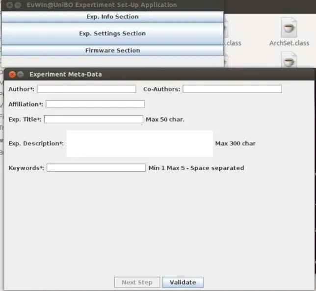
2.9 Flextop Java Application. . . 42
2.10 Flextop Java Application. . . 43
2.11 Unicast traffic: RTT as a function of the number of hops when trans-mitting 20 bytes of payload in static conditions. . . 56
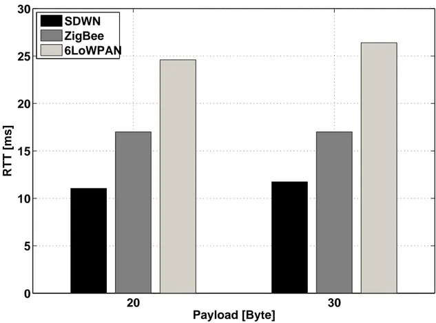
2.12 Unicast traffic: RTT as a function of the payload size in the case of one hop and static conditions. . . 57
2.13 Unicast Traffic: RTT for the different protocols in the case of static and quasi-static conditions, setting 20 bytes of payload and 2 hops. . 59
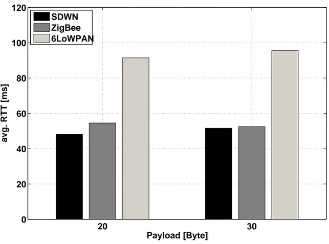
2.14 Multicast traffic: Average RTT as a function of the payload size. . . . 60
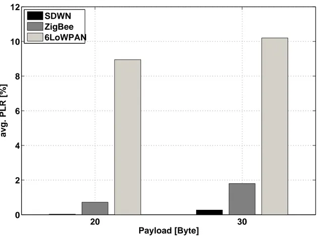
2.15 Multicast traffic: Average PLR as a function of the payload size. . . . 61
2.16 The carrier frequencies of IEEE 802.11 and IEEE 802.15.4. . . 67
2.17 Set-up of the IEEE 802.11 Network . . . 68
2.18 PLR for the different devices for overlapped channel and unicast trans-mission. . . 74
2.19 PLR for the different devices for overlapped channel and broadcast transmission. . . 75
2.20 RTT averaged among devices for unicast transmission. . . 77
2.21 RTT as a function of the overhead for device 22. . . 78
2.22 Downscaling description. . . 82
2.23 Downscaling methodology. . . 87
2.24 Channels overlapping within the 2.4 GHz band. . . 93
2.25 Map of the devices located in the corridor, with the corresponding pixels. 96
2.26 Map of the devices located in the flat, with the corresponding pixels. 97
2.27 Zigbee and Wi-Fi networks setup: a) IEEE 802.15.4 network, b) WiFi network. . . 98
2.28 REM in the corridor scenario: a) One Wi-Fi net, one 802.15.4 net, one BT net; b) Two Wi-Fi net, one 802.15.4 net. . . 98
2.30 REM in the flat: mean values. . . 100
2.31 REM in flat scenario: a) IEEE 802.15.4 Active Scan REM on channel 26; b) WiFi scan. . . 100
2.32 Coverage map in the presence of Wi-Fi interference. . . 102
2.33 REM in corridor scenario for the case of 1 Wi-Fi net, 1 802.15.4 net and 1 BT net. . . 103
3.1 M2M application through a LTE network . . . 111
4.1 PMF GAP wrt optimal solution . . . 136
4.2 ECDF of Solving time . . . 137
4.3 Overview of LTE-EPC Network Simulator (LENA) simulation compo-nents . . . 138
4.4 LENA: LTE-EPC protocol stack. Data Plane . . . 139
4.5 High level scenario. . . 140
4.6 Simulated Scenario . . . 142
4.7 Throughput vs Fairness - Video surveillance (LQ), Traffic Monitoring 147
4.8 Delay - Video surveillance (LQ) . . . 148
4.9 Delay - Traffic Monitoring . . . 149
4.10 Throughput vs Fairness - Video surveillance (LQ) and Video surveil-lance (HQ) . . . 150
4.11 Delay - Video surveillance (LQ) and Video surveillance (HQ) . . . 151
4.12 Throughput vs Fairness - Traffic Monitoring and Video surveillance (HQ)152
4.14 Throughput vs Fairness - Traffic Monitoring (25%), Video surveillance (LQ)(25%) and Video surveillance (HQ)(50%) . . . 154 4.15 Delay - Traffic Monitoring (25%), Video surveillance (LQ)(25%) and
Video surveillance (HQ)(50%) . . . 155 4.16 Channel and Application Aware - Throughput - Traffic Monitoring and
Video surveillance (HQ) . . . 158 4.17 Channel and Application Aware - Delay - Traffic Monitoring and Video
surveillance (HQ) . . . 159
5.1 Carrier Aggregation. . . 171 5.2 Class relations. . . 174 5.3 Lte Enb Data Plane Architecture . . . 176 5.4 Sequence Diagram of downlink BSR . . . 177 5.5 Lte Enb Control Plane Architecture . . . 178 5.6 Sequence Diagram of Data Radio Bearer Setup . . . 179 5.7 Lte Ue Data Plane Architecture . . . 181 5.8 Carrier Aggregation Ul Tx Opportunity . . . 182 5.9 Lte Ue Control Plane Architecture . . . 183
2.1 Average Received Powers [dBm] Matrix for -5 dBm. . . 49
2.2 Parameter Settings . . . 52
2.3 MAC Service Data Unit lengths . . . 53
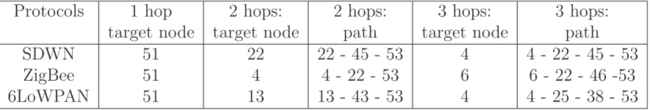
2.4 Target node(s) with the number of hops and paths. . . 55
2.5 Overhead: comparison among protocols. . . 58
2.6 Throughput [kbit/s] comparison: unicast and multicast. . . 62
2.7 20 nodes network: Comparing RTT and PLR. . . 62
2.8 Dynamic conditions: Comparing SDWN and ZigBee. . . 63
2.9 Average Received Powers Matrix . . . 71
2.10 ED Measurement: No Interference and Overlapped Channel . . . 72
2.11 ED Measurement: Non Overlapped Channel . . . 72
2.12 Wifi Utilization [%] . . . 73
2.13 Overhead [%] for the different cases . . . 76
2.14 RTT [ms] for broadcast transmission and overlapped channel . . . 79
4.2 CPLEX Analysis results . . . 134 4.3 CPLEX Analysis results: details over an instance . . . 134 4.4 Simulation System Parameters . . . 142
This thesis focuses on the paradigm of Heterogeneous Networks, whose concept is proposed in next chapter, along with the motivations supporting the study performed and the research approach followed. Since a significant part of the thesis results were obtained within the European FP7 Network of Excellence (NoE) “Newcom♯”, its structure and main goals are presented hereafter. Finally, the description of the thesis outline concludes this introduction. The Ph.D. was performed in the the Department of Electrical, Electronic and Information Engineering “Guglielmo Marconi” (DEI) at the University of Bologna (Italy). A large part of the contributions presented in this dissertation have been produced in collaboration with different universities and research centers along with periods of stay as visiting researcher over the three-year Ph.D. period.
Motivation
In the last 3-5 years the Internet of Things (IoT) became a paradigm very well know even outside the telecommunication specialist community. Among the plethora of different definitions of IoT, in this context the more interesting is the one provided by
International Telecommunication Union (ITU) [1], i.e. ”A dynamic global network of infrastructure with self-configuring capabilities based on standard and inter-operable communication protocols where physical and virtual ’things’ have identities, physical attributes and virtual personalities, use intelligent interfaces and are seamlessly inte-grated into the information network”. In a sense, the latter definition is the leitmotiv of this Ph.D., in fact according to this vision it is very important to understand the performance limits, advantages and disadvantages to use a certain approach or an-other. In this thesis different approaches to IoT concept are analyzed, standard and proprietaries solutions are tested and results highlight when it is more convenient to use one solution against another. One purpose of this thesis is focus on short to medium term research: solution already existing on the market are used and a particular emphasis is given to the implementation issues and to development tools.
Context of the Thesis: Newcom♯
NEWCOM♯ (Network of Excellence in Wireless Communications) was a project funded under the umbrella of the 7th Framework Program of the European Commis-sion. NEWCOM♯ pursued long-term, interdisciplinary research on the most advanced aspects of wireless communications like Finding the Ultimate Limits of Communi-cation Networks, Opportunistic and Cooperative CommuniCommuni-cations, or Energy- and Bandwidth-Efficient Communications and Networking.
Complementarily, NEWCOM♯ aimed to build the so-called European Lab on Wireless Communications for the Future Internet (EuWIn), a federation of three sites in three European Countries that will host researchers working on a number of topical areas like Advanced Radio Interfaces, the Internet of Things, and Flexible
Communication Terminals.
The NEWCOM♯ project is structure in 4 tracks:
• Track 1 - Theoretical Research Issues (R&I)
• Track 2 EuWIn: The European Lab of Wireless Communications for the Future Internet (R&I)
• Track 3 Training, Dissemination and Human Capital (S&I)
• Track 4 Management (M)
As the tracks’ title suggested the research activities have been performed in track 1 and track 2. Track 1 has been mainly devoted to theoretical research activities; meanwhile track 2 has been devoted to experimental activities. The main contribution of this this Ph.D. have been performed in WP1.3 and WP 2.2.
EuWIn
Due to its novelty and the potential impact of EuWIn onto European research and industrial context, in this subsection the main goals and a briefly description are given. EuWin aims to create a European reference lab on wireless communications where an experimental validation and realistic performance assessment of a selected subset of theoretical research activities conducted in Track 1. On one hand, EuWIn is expected to further strengthen the integration of partners research activities and agendas, both at the theoretical and experimental levels; and, on the other, to foster Industry-academia cooperation, dissemination and liaison by making academic research closer to industrial needs and interests. Furthermore, the lab provides a unique training
environment for a new generation of researchers with solid skills and background in experimental research.
Three main sites were selected to host EuWIn: CTTC in Barcelona (Spain), CNRS/EURECOM in Sophia-Antipolis (France), and CNIT/Univerisity of Bologna (Italy).
EuWIn@CNIT/Bologna
Networking technologies for the Internet of Things (IoT) with mobile clouds, where networks characterized by mobile nodes that interact with the fixed infrastructure are investigated. Large scale wireless sensor networks are studied and modelled in the context of Smart City as well as indoor applications. Lab facilities allow the imple-mentation of different routing and cooperative signal processing algorithms and the measurements of different metrics (delays, consumed energy, packet losses, through-put) over the network. The lab targets also the implementation of delay tolerant networking paradigms, through the mobile component of the network made acces-sible; the mobility patterns of mobile clouds are measured and modeled. Finally, indoor localization algorithms based on UltraWideBand (UWB) nodes are studied, in cooperation with the EuWIn@CTTC site. The HW/SW platforms are remotely accessible.
Structure of the Thesis and Approach
The description of the goals of this thesis, given in previous sections, and of the ap-proach followed highlights the complexity of the investigated topic and the challenges behind it.
During this Ph.D. two different approaches have been used: experimental and theoretical. The experimental approach takes advantages from the use of EuWIn, hence the main achievements obtained in short range solution for IoT have been obtained through experimental results. Meanwhile, due to its complexity a theoreti-cal/simulation approach to cellular network solution for IoT have been used.
Chapter 1 is devoted to the IoT concept: applications, issues and challenges are addressed. A focus on the IoT standardization world is given. Finally, the Machine to Machine (M2M) concept is presented and the traffic model used in this dissertation is shown.
In Chapter 2 IoT short range solutions are addressed. Different standards and proprietary solutions are described. This chapter is mainly devoted to experimental activity, hence most of the results have been obtained through EuWIn.
As it is well known M2M application are of paramount important in the cellular world. Chapter 3 is devoted to present the main issues and research challenges related to M2M applications in cellular network with a special focus on 4G networks.
Chapter 4 presents results obtained mainly in a joint research activity within the track 1 of NewCom♯ project. In particular, a mathematical framework is provided and simulation results are given when M2M application are running on Long Term Evolution (LTE) system. This work is mainly focus on Radio Resource Management (RRM).
Finally, Chapter 5 is devoted to LTE-Advanced (LTE-A) network, and in parti-cular it describe the Carrier Aggregation feature, its implementation on a network simulator and a mathematical model for RRM in LTE-A network.
IoT and M2M
In [1] ITU, highlight the huge impact of the IoT above the Internet. In fact, Internet and modern communications technologies introduced the possibility to be connected any time communication, on the move, night and daytime (first dimension); any place communication, indoor with or without the computer and outdoor (second dimen-sion). IoT adds the third dimension: any thing communication; between computers, human to human, human to thing, thing to thing. It is clear that Machine Type Communications (MTC) and M2M applications are key components of the IoT con-cept. MTC are defined as a form of data communications which do not need human interaction. The number of human users of mobile networks is coming to saturation, while the M2M domain is seen as a new revenue opportunity. In general, the esteems agree that the number of M2M connections will grow in the coming years [2]. Market researches such as [3] [4] predict up to 800 million machine to machine (M2M) con-nections by 2015, while standardization organizations argue for very high densities of M2M devices in broadband bandwidths [5]. Mobile operators like Telnor, Voda-fone and Telefonica have created dedicated units or even companies to focus on M2M business opportunities. Similarly, mobile vendors are creating their own visions, such
as the Ericsson’s ”50 billion connected devices”. Large Information Technology (IT) vendors like IBM or HP also have ambitious plans to connect and exploit information generated by trillions of sensors. At the present time, the most interesting applica-tions from the commercial point of view are related to smart grids, automatic water and gas meter readings. However, the M2M application space is vast and includes security, health monitoring, remote management and control, intelligent transport systems, ambient assisted living, etc. In addition, M2M is more than just connected devices sharing data, but it is also about collecting and distributing the data effi-ciently, often in real time and with desired Quality of Service (QoS) requirements, in terms of e.g. latency. The communication network plays an important part of the ecosystem and its ability to support M2M services and traffic requirements, will be crucial for such a distributed setup.
1.1
IoT Applications
This section provides an overview of major applications of the IoT paradigm. The main application fields considered are:
• Smart Cities: the IoT can help the design of smart cities e.g., monitoring air quality, discovering emergency routes, efficient street lighting, watering gardens etc.
• Prediction of natural disasters: the combination of sensors and their au-tonomous coordination will help to predict the occurrence of land-slides or other natural disasters and to take appropriate actions in advance.
fleet of cars for an organization. The IoT helps to monitor their environmental performance and process the data to determine and pick the one that needs maintenance.
• Water scarcity monitoring: the IoT can help to detect the water scarcity at different places. The networks of sensors, might not only monitor long term water interventions such as catchment area management, but may even be used to alert if an upstream event, such as the accidental release of sewage into the stream, might have dangerous implications.
• Medical applications: the IoT can also find applications in medical sector for saving lives or improving the quality of life e.g., monitoring health parameters, monitoring activities, support for independent living, monitoring medicines in-take etc.
• Agriculture application: a network of different sensors can sense data, perform data processing and inform the farmer through communication infrastructure e.g., SMS about the portion of land that needs particular attention. This may include smart packaging of seeds, fertilizer and pest control mechanisms that respond to specific local conditions and indicate actions. Intelligent farming system will help agronomists to have better understanding of the plant growth models and to have efficient farming practice by having the knowledge of land conditions and climate variability. This will significantly increase the agricul-tural productivity by avoiding the inappropriate farming conditions.
• Smart security: the IoT can also find applications in the field of security and surveillance e.g., area surveillance, tracking of people and assets, infrastructure
and equipment maintenance, alarming etc.
• Smart metering and monitoring: the IoT design for smart metering and moni-toring will help to get accurate automated meter reading invoice delivery to the customers. the IoT can also be used to design such scheme for wind turbine maintenance and remote monitoring, as well as gas, water and environmental metering and monitoring.
• Smart Homes: the IoT can facilitate the design of smart homes e.g., energy consumption management, interaction with appliances, detecting emergencies, home safety and security etc.
• Intelligent transport system design: the Intelligent transportation system will provide efficient transportation control and management using advanced tech-nology of sensors, information and network. The intelligent transportation can have many interesting features such as non-stop electronic highway toll, mobile emergency command and scheduling, transportation law enforcement, vehicle rules violation monitoring, reducing environmental pollution, anti-theft system, avoiding traffic jams, reporting traffic incidents, smart beaconing, minimizing arrival delays etc.
1.1.1
Issues and challenges
The IoT can change the shape of the Internet and can offer enormous economic benefits but it also faces many key issues and challenges. Some of them are briefly described below.
able to draw power from the mains, and have batteries at best. This means that finding enough energy to power processing and communication is a major challenge. Whilst we are ready to recharge our mobile phones on a daily basis, changing batteries in millions of objects is impractical. Any stack must therefore exhibit a low average power consumption.
• A Highly Reliable Communication Stack. Although the Internet is a best-effort transport medium, protocols incorporate error detection, retrans-missions and flow control. These techniques are applied at various protocol layers concurrently, which leads to a reliable end-to-end experience, albeit in a rather inefficient way. For the IoT to merge seamlessly into the Internet, it is necessary to offer the same reliability we are used to on the Internet with the additional requirement that is the highest possible efficiency.
• An Internet-Enabled Communication Stack. Enabling another dialect of the Internet has profound implications on the protocol design. The Internet is exhibiting emergent behavior today because communication is bidirectional; it is hence of utmost importance to ensure that communication from objects but also towards objects is facilitated. Furthermore, the explosion of the Internet can arguably be attributed to the ability of any machine around the world to talk to any other machine, all this facilitated by one universal language, IP; it is hence of paramount importance that the IoT is IP enabled.
1.2
IoT scenarios - Heterogeneous networks
In the past years, IoT market players tried to build silos or vertical applications. This means that for each vertical IoT application they maintain the entire communication chain from gathering the data to provide the information in aggregated form through web applications. This behaviour results on a huge amount of both standard and proprietary solutions. In fact, the main challenge for the future of IoT is for sure the needs to interconnect and integrate heterogeneous networks. The standardization bodies are already spending effort to try to contain the phenomenon. The integration of heterogeneous network for IoT face several challenges, including:
• integrate together communication protocols into a IP-based environment
• integrate communication protocols used in different application layer
1.3
Standardization players
This section is given an overview on the main standardization players that are very active on the IoT.
1.3.1
3GPP
As it is well known, 3GPP is a standardization body for cellular network standards. In the last years, it has been growing attention on IoT, according to this several functionality M2M related have been added in LTE and LTE-A releases starting from R10.
1.3.2
ETSI
ETSI is a pan-European standards producers for ICT. In the past it has been provided standard for fixed, mobile, radio and internet technologies. ETSI already spent a huge effort on IoT contest, it published documents in different fields, e.g. smart metering, smart grid, Internet of vehicle and so on. However, the main focus of ETSI is on system level platform and in particular:
• end-to-end security
• abstraction layer and data models
• define procedure and model for M2M networks inter-operability
• define inter-operability with the 3GPP cellular networks.
1.3.3
oneM2M
oneM2M is a worldwide Partnership Project that has as partner ETSI, Association or Radio Industries and Business (ARIB - Japan), China Communications Standard Association (CCSA China), Telecommunications Technology Association (TTA -Korea), Telecommunication Technology Committee of Japan (TTC - Japan), Alliance for Telecommunications Industry Solutions (ATIS - US). Moreover, several industry organization partners have been joined this project, like HGI! (HGI!) and Open Mo-bile Alliance (OMA). The main purpose and goal of oneM2M is to develop technical specifications which address the need for a common M2M Service Layer that ca be readily embedded within various hardware and software, and relied upon to connect the myriad of devices in the field with M2M application servers worldwide.
1.3.4
CEN/CENELEC
CEN/CENELEC play a complementary roles in the development for IoT standards with ETSI. The primary tasks for this two European standardization bodies are:
• integrate sensor data RFID driven system to enhance their performance and effectiveness
• define application system that using ubiquitous sensor networks
• integrate smart object on the Future Internet with particularly focus on object discovery services.
1.3.5
IEEE
Several IEEE associations have been dealing with IoT context. Within the IEEE societies several standards have been published spanning from Cloud Computing, to eHealt, eLearning and Intelligent Transportation Sytems. However, one of the main achievement in the standardization for IoT is for sure the publication of IEEE 802.15.4 which is the ’de facto’ standard for several M2M application protocols nowadays.
1.3.6
IETF
IETF is a worldwide association structured in different working group according to the topic they address. Indeed in the IoT context the most valuable product is the adaptation of Internet Protocol v6 (IPv6) for embedded devices, i.e. IPv6 over Low power Wireless Personal Area Networks (6LoWPAN). Moreover, IETF released
different Request for Comment (RFC) on Routing Protocol for Low power and Lossy Networks (RPL).
1.3.7
ITU-T
ITU-T is involved in the IoT standardization activities since 2005 when the report ”The Internet of Things” was published. The interest of ITU-T span from IoT appli-cations to terminology, requirement, business models as well as security and testing. Moreover several IoT related study group have been formed within the ITU-T.
1.4
M2M Traffic Models
In this section a briefly description of M2M applications and services is presented, moreover some references on M2M traffic model are given. As for the traffic models, contributions in literature for MTC are still little. Among them, in this section are highlighted the advancements achieved in the context of the FP7 Lola Project, where different M2M applications are analysed to found a model that generally describes the M2M traffic. The adopted model is based on Markov Chains and on a general On-Off model with different distribution for the packet sizes and inter-arrival times of packets (LogNormal, Gaussian, Weibull, Constant size). Also 3GPP has devoted efforts to the classification and modelling of M2M traffic, in 3GPP TSG RAN WG1. Additional work can also be found in this contribution in literature [6].
The peculiarities of M2M devices are addressed in the 3GPP Technical Report TS22.368 [7], where a detailed prediction and classification for the M2M services is
presented. In the following the main characteristics of the M2M services are summa-rized:
• The number of M2M devices is expected to be 1-2 order of magnitude larger than the number of Human to Human (H2H) devices
• Currently the M2M traffic is almost uplink
• A M2M transmission session is short in time, but the sessions are frequently initiated
• In each session just few packets are sent and, in general, those packets are expected to be very short
• Several M2M applications are insensitive to delay.
Another degree of complexity in modelling the M2M traffic is related to the pos-sibility of aggregate data. The same M2M application running on the same network protocol can produce two different traffic patterns if data aggregation is performed or not.
In [8] and [9] the M2M traffic models are studied more in details. The M2M traffic model generally adopted in this thesis is a typical On-Off model and it is defined in the follow. Figure 1.1 shows the state diagram of the traffic model of a M2M device, which is based on three states:
• OFF State: in this state the devices are in a deep sleep mode and only a very low power clock is running. The devices move to the ON state when a timer expires.
OFF ON Monitoring
ON Alarm Mode
Sleep
Figure 1.1: M2M state diagram
• ON/Monitoring Mode: the devices in this state generate information on a time-driven fashion. In practice, the device monitors some physical variable and sends periodical information.
• ON/Alarm Mode: this model depends on the application and type of sensor the device is equipped with. In general, the device is triggered by a particular event, when there is the need to send more frequent information than in the monitoring mode. For instance, a temperature sensor in a building provides reg-ular information, e.g., every 5-10 minutes, on the temperature in the building. However, if the temperature exceeds a certain threshold, this may be associated to a fire alarm, so that the device enters the alarm mode and sends information every 1-5 seconds.
1.5
Conclusions
In this chapter the definition of IoT was given. The main trends, applications and challenges have been addressed. Furthermore, a view on the standardization land-scape for IoT has been given. Then a focus on M2M world has been presented. In this context, the main advancements have been referenced and the M2M device
IoT short range solutions
This chapter aims at presenting three communication protocols stacks for IoT short range applications. More in details, it presents two standard solutions (i.e. Zigbee [10] and 6LowPan [11]) and a Software Defined Network (SDN) approach called Software Defined Wireless Network (SDWN). All those communication protocols stacks rely on IEEE 802.15.4 standard [12] for Physical layer (PHY) and Medium Access Control layer (MAC) layers. For that reason section 2.1.1 is dedicated to the common PHY and MAC layers where the specification of IEEE 802.15.4 standard are briefly sum-marized. This chapter is not intended to be a comprehensive survey on all the IoT short range solutions. On the opposite, the author choose to focus on these solutions since IEEE 802.15.4 based Wireless Sensor Network (WSN) solutions seem to be the most used in industrial applications. The rest of the chapter is organized as follows: section 2.1 briefly describes the standard of interest; meanwhile in section 2.2 the testing platform is presented. Sections 2.4 and 2.5 presents a performance analysis: i) comparison between the three protocol stacks introduced above; ii) a study of co-existence issue between IEEE 802.11 and Zigbee; iii) tools usage for fast deploying a real WSN.
2.1
Standards
In this section, the WSN protocol stack of interest are presented, a briefly introduction on the common PHY and MAC layers in also given.
2.1.1
IEEE 802.15.4
IEEE 802.15.4 is ’de facto ’ standard for WSN applications. It is a wireless technology standardized and optimized for short-range communication, with relaxed throughput and latency requirements, that are also called in WPAN. As anticipated above, the IEEE 802.15.4 Working Group1 focuses on the standardization of the Layer 1 (L1)
and Layer 2 (L2) of the ISO/OSI protocol stack, i.e. PHY and MAC. In the following, are briefly described the main features and characteristics of IEEE 802.15.4 standard. For a exhaustive description refer to the standard [12].
2.1.1.1 IEEE 802.15.4 PHY
The standard specifies 27 half-duplex channels in total. Those channels are define across three frequency bands as follows:
• 868 MHz band, only 0.6 MHz are reserved (it is ranging from 868.0 MHz to 868.6 MHz) and it is used only in Europe. The modulation format is a cosine-shaped Binary Phase Shift Keying (BPSK), with Direct Sequence Spread Spectrum (DSSS) at chip rate 300 kchip/s. Due to the few bandwidth reserved only one channel is defined with a data rate of 20 Kbps.
1
• 915 MHz band, in this case 26 MHz in total are reserved, ranging between 902 and 928 MHz. This band is used only in North America and Pacif area. As modulation format a raised-cosine-shaped BPSK is implemented with DSSS at chip-rate 600 kchip/s. In total 10 channels with 40 Kbps data rate are available.
• 2.4 GHz Industrial Scientific Medical (ISM) band, in total 83.5 MHz are reserved (from 2400 to 2483.5 MHz). This band is worldwide used. The modulation for-mat is half-sine-pulse-shaped Offset Quadrature Phase Shift Keying (O-QPSK) with DSSS at 2 Mchip/s. In total 16 channels are available. The data rate is 250 Kbps.
Regarding the channel bandwidth, in the first two cases is 0.6 MHz where the car-riers are separated by 2 MHz; meanwhile in the latter case, the channel bandwidth is 3 MHz (first lobe) and the carriers are separated by 5 MHz. One of the keys of suc-cess of IEEE 802.15.4 standard is the low energy consumption. In fact, the standard defines a duty cycle of (up to) 99 % of inactive time. This feature allows networks properly designed to work for months rely on a commercial small size battery supply. The transmission, according to IEEE 802.15.4 standard, is organized in frames. More in details, depending on the purpose, four different frame structures are designated as Physical Protocol Data Unit (PPDU): a beacon frame, a data frame, an acknowledge-ment frame and a MAC command frame. All those frame structures have in common the following fields: Synchronization Header (SHR), Physical Header (PHR) and a Physical Service Data Unit (PSDU). The latter is composed of a MAC Payload Data Unit (MPDU) which in turn is constructed with a MAC Header (MHR), a MAC Footer (MFR) and a MAC Service Data Unit (MSDU). Only exception is the acknowledgement frame, which does not contain an MSDU. In order to detect the
PPDU
Preamble Sequence Start of Frame Delimiter Frame Length PSDU SHR PHR MPDUMAC
ControlFrame SequenceNumber AddressingFields SpecificationSuperframe FieldsGTSPending Address Fields Beacon Payload Frame Check Sequence
Figure 2.1: IEEE 802.15.4 physical layer frame structure
correctness of received messages, a Cyclic Redundancy Check (CRC) is used. A IEEE 802.15.4 PHY frame example is given in figure 2.1, this in particular is related to the beacon frame.
2.1.1.2 IEEE 802.15.4 MAC
MAC layer provides access control to a shared channel and reliable data delivery. IEEE 802.15.4 MAC layer, together with the Link Layer Controller (LLC), defined the data link layer of ISO/OSI model. The main function of IEEE 802.15.4 MAC layer are: provide support for the possible network topologies described in the stan-dard (i.e. star and peer-to-peer topologies), generate the acknowledgment (ACK) frame, association and disassociation, security control. IEEE 802.15.4 uses a Listen-before-talk (LBT) protocol in order to reduce the probability of collision with other
ongoing transmissions. In fact, it relies on a Carrier Sense Multiple Access with Col-lision Avoidance (CSMA/CA) algorithm. In the standard two different operational modes are defined, i.e. beacon-enabled and non beacon-enabled. Unslotted CSMA/CA protocol is used in non beacon-enabled mode. The algorithm is implemented using units of time called backoff periods and it is shown in Fig. 2.2. Each node initializes two variables, NB and NE, for each transmission attempt. NB defines the number of times the CSMA/CA algorithm is required to backoff while attempting the transmis-sion; the initial value is set to zero and cannot be larger than NBmax, i.e. equal to
4 by default. Meanwhile, BE ranges between BEmin = 3 and BEmax = 5. As it is
shown in figure 2.2, BE is used for defining the range of random number of backoff periods, i.e. range(0, 2BE − 1). The node that wants to transmit: i) initializes NB
and BE; ii) delays transmission for a random number of backoff periods; iii) performs sensing; iv) checks if the channel is free, in the positive case it transmits; in the neg-ative case it jumps to step v) increases NB and BE and, in case NB > NBmax the
transmission fails (i.e. node did succeed in accessing the channel), otherwise starts again from step ii). The second operational mode, i.e. beacon-enabled, the channel access is managed through a superframe. In this case the node which is appointed to be the network manager, called coordinator or sink, sends a specific message, i.e. beacon, that identifies when a new superframe starts. The superframe structure is shown in figure 2.3. It is composed of: i) Contention Access Period (CAP) which is the portion of superframe where nodes perform CSMA/CA procedure to access the channel; ii) Contention Free Period (CFP), the coordinator allocated a portion of the superframe, aGuaranteed Time Slot (GTS), to a specific node (up to 7 GTSmay be assigned). The standard define GTS use as optional, however it is mandatory to
NB = 0 BE = BEmin
Delay for random (2^BE -1) unit backoff periods
Perform Sensing
Channel idle?
NB = NB + 1 BE = min { BE+1, Bemax)
N Success Y NB > NBmax? Failure Y N
G T S G T S G T S G T S G T S G T S G T S Inactive Part Beacon Interval G T S Superframe duration CFP Beacon Beacon
Figure 2.3: IEEE 802.15.4 CSMA/CA algorithm in beacon-enabled case
reserve enough time for CAP phase; iii) in order to reduce nodes’ energy consumption an inactive part can be reserved. In the last case nodes can switch in sleep mode and saves some energy by turning off some hardware. The CSMA/CA algorithm used in beacon-enable mode is slightly different with respect to the former presented. The algorithm it is shown in figure 2.4. In this case the backoff and sensing phase are run CW = 2 times.
2.1.2
Zigbee
This section is dedicated to the Zigbee standard, for the scope of this dissertation, here the focus is only on the routing protocols defined by the protocol standard. Other important features, security, application layer are not discussed here. For all those aspects it is suggested to read [10] and [13].
2.1.2.1 Routing: Ad-hoc On-demand Distance Vector (AODV)
ZigBee Alliance proposed a well-known routing protocol as default protocol for IEEE 802.15.4/ZigBee networks: AODV [14]. According to AODV protocol, a node which has data to be transmitted, sends a Route Request (RREQ) using broadcast mode in order to discover the appropriate path. Each device receiving the RREQ packet
NB = 0 CW = 2 BE = BEmin
Delay for random (2^BE -1) unit backoff periods
Perform Sensing
Channel idle?
NB = NB + 1 BE = min { BE+1, Bemax)
N Success NB > NBmax? Failure Y N CW = CW - 1 CW = 0 ?
retransmits it, by broadcast, until it reaches the destination node. During the process of rebroadcasting the RREQ, intermediate nodes record in their route discovery tables the address of the sender from which the first copy of the broadcast packet was received, and the corresponding link cost (see [13]). The comparison among path costs of packets with the same RREQ allows choosing the best path. Once the destination node receives the RREQ, it responds by sending a Route Replay (RREP) packet in unicast back to the source along the reverse path.
In case of link failures, or expiration of the entry into the routing table, the device repeats the RREQ/RREP transmission in order to refresh the route.
The RREQ/RREP procedure is used only for the transmission of unicast data packets.
In the case of multicast transmission, a path between the coordinator and the multicast group should be established. The standard implementation uses AODV to establish the route between the coordinator and the multicast group; in this case the RREQ packet, sent in broadcast, includes the address of the multicast group to be discovered. Nodes in the network that are linked to the target multicast group, send a RREP back to the coordinator through the selected path. The latter path is used for the transmission of query packets. In the uplink direction, that is from the queried nodes to the coordinator, nodes use the same protocol as for the unicast transmissions.
2.1.2.2 Routing: Many-to-One (MTO)
MTO routing allows to establish a tree topology, rooted at the coordinator. In order to form and maintain the tree, the coordinator periodically sends a Many-to-One
Route Request (MTO-RR) packet in broadcast. Each node, receiving a MTO-RR before retransmitting it, reads the accumulated path cost (i.e., the sum of the costs of the links of the reverse path toward the coordinator) included in the packet, and selects the next hop toward the coordinator. In particular, if a node receives several MTO-RRs from different nodes, it elects as a next hop the node characterised by the minimum total path cost to the coordinator. At the end of this MTO-RR trans-mission, all nodes in the network are aware of the next hop to be used in order to transmit their data to the coordinator, that is their parents in the tree. However, if the coordinator wants to know the path to reach a specific node in the network (or a set of nodes by multicasting), MTO routing should be combined to Source Routing (SR). After the MTO-RR transmission, once a node has a data packet to be sent to the coordinator, it first sends a Route Record (RREC) packet through the selected path. Each node in the path receiving the RREC packet, adds in the relay list field its own address and forwards the new RREC packet toward the coordinator. The co-ordinator analyses the RREC packet and stores that information in the Source Route Table. Each time the coordinator has to send a packet to a node, it reads the relay list from this table and sends the packet through the selected path.
In order to let nodes compute the link costs to be used in the MTO routing for the selection of the path, each node in the network periodically sends Link Status packets in broadcast at one hop. Each node receiving the Link Status packet computes the link cost, being a function of the link quality indicator of the received packet [15].
Even though MTO-RRs are periodically sent by the coordinator and are not gen-erated on-demand (which would make the protocol pro-active), ZigBee saves the re-active feature through the use of Ad hoc On-Demand Distance Vector (AODV)
protocol [14], when needed. In particular, in case of link failure, AODV is used for discovering a new path toward the destination. According to AODV, a node search-ing for a destination node sends a Route Request packet (RREQ) in broadcast, which is retransmitted by all receiving nodes until it reaches the destination. During the process of rebroadcasting the RREQ, intermediate nodes record in their route dis-covery tables the address of the RREQ sender, and the corresponding total cost of the reverse path to the source. The comparison among paths’ costs of packets related to the same RREQ allows choosing the best path. Once the destination receives the RREQ, it responds by sending a RREP in unicast back to the source along the reverse path.
2.1.3
6LowPAN
The IETF IPv6 over Low power Wireless Personal Area Networks (6LoWPAN) work-ing group published first document in August 2007 [16]. Among the several available IPv6 over Low power Wireless Personal Area Networks (6LoWPAN) solutions, in this dissertation is used µIPv6 stack, implemented in Contiki operating system2 and
ported it on the Flextop platform, i.e. the testbed platform used to compare the protocols.
2.1.4
Protocol Stack
The 6LoWPAN protocol stack is shown in Fig. 2.5. Due to the fact that the direct integration between IPv6 and IEEE 802.15.4 lower network layers is not possible, the
2
IETF 6LoWPAN working group has specified an adaptation layer and header com-pression scheme for transmission of IPv6 packets over IEEE 802.15.4 radio links. The purpose of adaptation layer is to provide a fragmentation and reassembly mechanism that allows IPv6 packets (Maximum Transmission Unit for IPv6 is 1280 bytes) to be transmitted in IEEE 802.15.4 frames, which have a maximum size of 127 bytes of the MPDU. At network layer, the IPv6 routing protocol, RPL, is used (see be-low for details). At the transport layer, User Datagram Protocol (UDP), providing best-effort quality of service, is applied. Finally, at the application layer, Constrained Application Protocol (CoAP) is present.
2.1.4.1 The Routing Protocol
According to RPL, a Destination-Oriented Directed Acyclic Graph (DODAG), where each node may have more than one parent toward the root, is built [17]. One of the parents is called preferred parent, and it is used for routing toward the root. In the rest of this chapter, the root node is also referred as coordinator.
The topology is set-up based on a rank metric, which encodes the distance of each node with respect to its reference root, as specified by the objective function. A common metric, used in the performance analysis in the follow sections, is the hop count metric; therefore the rank of a given node represents the number of hops separating the node from the coordinator. Paths in the DODAG are selected in order to minimise the rank.
RPL nodes exchange signaling information in order to setup and maintain the DODAG. The construction of DODAG is initiated by the root that sends DODAG Information Object (DIO) messages to its neighbours to announce a minimum rank
value. Upon receiving a DIO message, an RPL node will: i) update the list of its neighbors; ii) compute its own rank value; iii) select its preferred parent used as next hop to reach the root as the strongest one (i.e., the one from which it received the largest power); iv) start transmitting DIO messages, containing its respective rank in the DODAG (a distance to the DODAG root according to the hop-count). RPL nodes may also send DODAG Information Solicitation (DIS) messages when joining the network to probe their neighbors and solicit DIO messages.
Finally, Destination Advertisement Object (DAO) messages are used to propagate the destination information upward along the DODAG. DAO messages are sent in unicast by the RPL node to the selected parent to advertise its address. When a node receives a DAO, it updates its routing table and then this information is used by the DODAG root to construct downward paths. Each router in the path records the route identifier and the corresponding next hop toward the destination.
RPL uses an adaptive timer mechanism, called the Trickle timer, to control the sending rate of DIO messages. The Trickle algorithm implements a check model to verify if RPL nodes have out-of-date routing information. The frequency of the DIO messages depends on the stationarity of the network, and the frequency is increased when the inconsistency is detected. Once the network becomes stable, the Trickle algorithm exponentially reduces the rate at which DIO messages are emitted.
RPL supports both unicast and multicast traffics. In the case of multicast, one solution is using the Stateless Multicast RPL Forwarding (SMRF) protocol. Accord-ing to the latter, nodes join a multicast group by advertisAccord-ing its address in their outgoing DAO messages, which only travel upwards in the DODAG. Upon reception of message from one of its children, a router makes an entry in its forwarding table for
this multicast address. This entry indicates that a node in the DODAG is a member of the group. This router will then advertise this address in its own DAOs, and relay multicast datagrams destined to this address.
2.1.5
SDN approaches
The first implementation of SDWN was developed in October 2012 [18]. The main idea behind the protocol is to adapt a centralized approach, such as the one proposed in SDN networks, to a wireless environment, thus giving the opportunity to support the flexible definition of rules and topology changes.
2.1.5.1 Protocol Stack
The SDWN protocol stack is shown in Fig. 2.5: PHY and MAC layers are those of IEEE 802.15.4, while upper layers are inspired by the SDN paradigm.
A typical SDWN network is composed of a controller device, a sink node, as well as several other nodes. The controller gathers the information from nodes, maintains a representation of the network, and establishes routing paths for each data flow. The sink is the only node that is directly connected to the controller, and it acts as a gateway for nodes. In this implementation, the sink coincides with the network coordinator and its protocol stack is equivalent to that of a generic node.
The stack of a generic node is divided into three parts: the Forwarding Layer (FWD), the Aggregation Layer (AGGR), and the Network Operating System (NOS). The MAC layer provides incoming packets to the FWD layer that identifies the type of the packet. Six different types of packets are defined:
• Beacon: periodically sent in broadcast by all nodes in the network;
• Report: containing the list of neighbors of a node;
• Rule Request: generated when it receives a packet for handling which it has no information (i.e., the path);
• Rule Response: generated by the controller as a reply to the Rule Request;
• Open Path: used to setup a single rule across different nodes.
When a non-beacon packet is received by the FWD layer, it is sent to the NOS that searches for the corresponding rule in an appropriate data structure called Flow Table. The Flow Table stores all the rules coming from the controller. For each rule, there are three types of action that could be executed: forward to a node, modify the packet, or drop it. If a packet does not match any of the rules in the table, a Rule Request is sent to the controller.
2.1.5.2 The Routing Protocol
The path between the sink and the node for sending/receiving Rule Request/Rule Response packets must be chosen effectively, considering both reliability of the path and its length. Each node constantly stores its distance (in number of hops) from the sink, and the Received Signal Strength Indicator (RSSI) that is the level of power it receives from the next hop toward the sink. During the network initialization, each node is in a quiescent state waiting for messages. When the sink turns on, it sends a Beacon, containing the number of hops from the sink (zero in this case). When a node A receives the Beacon, it performs the following four operations:
• Add the source of the Beacon and the RSSI received in the list of nodes (neigh-bours table) that are one hop distant from A.
• Analyse the distance contained in the Beacon and the RSSI of the received message, then compare these values to the corresponding stored values: if the number of hops is lower and the RSSI is higher, the source of the Beacon is elected as the best next hop toward the sink, and the values stored in A are updated.
• The Beacon timer is activated and node A will periodically send its own Beacon in broadcast.
• The Report message timer is activated: the neighbours table of A is sent peri-odically to the sink node using the best next hop toward the sink. After each transmission, the list of neighbors is deleted in order to have an updated view of the network. The Report period must be greater than the period used to broadcast Beacon messages (Beacon period).
The information included in the Report messages are used by the controller to create a map of the network. Based on this representation, the controller is able to respond to Rule Requests and to decide the routing paths for data packets, while Rule Request will keep following the previously discovered path.
The actual implementation of the controller uses Dijkstra’s routing algorithm to solve Rule Requests. The weight of the edges in the topology representation is a function of the received RSSI.
A possible change in the network is notified to the controller using Report mes-sages. As specified above, the controller obtains periodically all the lists of neighbours,
according to the Report period that is bounded by the Beacon period. By decreasing the latter period, a faster responsiveness to environmental changes could be obtained to the detriment of having larger overhead.
In the actual implementation of SDWN, the controller sends a Rule Response only after receiving a Rule Request from a node and rules contained in the nodes expire after a configurable period of time. Therefore, at the end of this period, the controller receives a new Rule Requests for the unmanageable packets.
As previously mentioned, more than one action can be executed for an incoming packet, thus achieving the multicast communication. By performing multiple actions, the controller is able to clone an incoming message into multiple outgoing messages. Unfortunately, a drawback of this approach is that the multicast is locally executed by transmitting a series of unicast messages. In other terms, the broadcast nature of the wireless communication is not exploited.
2.2
Testing platform: EuWIn@UniBO
EuWin is a three site laboratory develop within the FP7 project NoE Newcom#. The three site are: Eurecom - Sophie Antipolis (FR), CTTC - Castelldefels (ES) and University of Bologna - Bologna (IT). Three testbeds are available at UniBO: FLEX-TOP, DATASENS and LOCTEST. [19] give an exhaustive description of the entire laboratory, while for the aims of this dissertation only FLEXTOP and DATASENS testbed are described.
APPLICATION UDP SDWN Adaptation Layer SDWN Network Operating System Flow Table management SDWN Aggregation Layer IEEE 802.15.4 MAC IEEE 802.15.4 PHY CONTROLLER Routing SDWN Forwarding Layer Neighbor discovery UDP 6LoWPAN Adaptation Layer Header compression Neighbor discovery IEEE 802.15.4 MAC IEEE 802.15.4 PHY ȝIPv6 Routing ContikiRPL (ICMP6) ZigBee Network Layer Addressing, Routing, Header IEEE 802.15.4 MAC IEEE 802.15.4 PHY APPLICATION APPLICATION / PROFILES Application Framework
Figure 2.5: Protocol architectures: SDWN (on the left), 6LoWPAN (in the center), and ZigBee (on the right).
Figure 2.6: The EuWInUniBO site platforms.
2.2.1
The FLEXTOP testbed
The general architecture is shown in Fig. 2.7.
FLEXTOP is a platform composed of (up to) one hundred programmable wireless nodes and a dedicated software environment. The radio transceivers are manufac-tured by Texas Instruments and are IEEE 802.15.4 compliant (PHY and MAC). The hardware architecture of the wireless nodes have been designed by CNIT/UniBO in collaboration with Embit srl, an Italian SME that acts as design center for Texas Instruments. The nodes have been jointly conceived by CNIT/UniBO and Embit in order to permit Over-the-Air (OTA) programming of the firmware that imple-ments the protocol stack. Through this platform any protocol stack compatible with 802.15.4 can be tested (e.g. Zigbee, or 6lowPAN as proposed by many IoT developers, etc.).
FLEXTOP is a remotely accessible testbed. While it is deployed at the premises of the University of Bologna, researchers are able to upload their firmware implementing the protocol stack (above MAC) on the wireless nodes, run the experiments and
Figure 2.7: Flextop general architecture.
download the log files including all experiments results.
The wireless nodes are deployed according to a fixed grid of positions in a corridor (see Fig. 2.8). However, the researcher using the testbed can set different values of transmit powers achieving very different network topologies (linear, star, double linear, etc.). In particular, nodes can be turned on and off independently during the experiments, and the creation of sub-sets of networks is possible. At start of each experiment, the network automatically measure and generate the matrix of channel gains, which is useful to certify the propagation environment. Experiments run at night, when nobody is allowed to walk in the corridor: therefore the experimental environment is stable for the full duration, making experiment results certified.
The nodes do not carry sensors. However, several types of sensor data can be simulated by programming the application layer of the nodes so as to let them generate data according to specific and realistic environmental conditions. Therefore, the one
49 50 51 52 41 42 43 44 45 46 47 48 37 38 39 40 33 34 35 36 25 26 27 28 29 30 31 32 21 22 23 24 1 3 1 4 1 5 1 6 1 2 3 4 5 6 7 8 1 7 1 8 1 9 2 0 53
Figure 2.8: Flextop nodes map.
hundred nodes emulate a true and flexible sensor network.
Packet Error Rates, Delays and Throughput are the performance figures that can be captured from the wireless network during the experiments.
Fig. 2.7 represents the architecture of FLEXTOP. Through a VPN connection a researcher can remotely access the lab facilities. Through a web browser it is possible to download the GUI application that is used to send the firmware and send the desired parameters of the experiment. In order to use FLEXTOP a researcher needs a PC with a VPN Client, a browser and a Java Virtual Machine installed.
The server allows the access to the user and it is used as a repository for experi-ments results; furthermore, on the server there is a database that stores all information related to the experiments (parameters, raw data, firmware, etc.).
layout that can be created by selecting specific nodes (52 nodes are active in this case).
Two gateways allow the interfacing between the server and the wireless nodes. They are single board computers based on ARM architecture running on embedded Linux. The aim of these devices is to communicate with the coordinators of the wire-less sensor network; the coordinators are connected to the gateways through a wired interface. The gateways also include sniffers which store in log files all information captured from the network (packets sent, source and destination addresses, etc.). The gateways are also responsible for storing the experiments results in a raw file.
Sniffers are TI CC2531 based devices. Through a custom firmware the researchers can directly communicate with the sniffers as well as send commands to them. Coor-dinators are TI CC2530 based devices. Through the gateways the researcher can send the new firmware to the coordinators. Coordinators manage the firmware performing the OTA download to all devices in the network.
The wireless nodes are also based on TI CC2530. The main specifications of these devices are as follows:
• 256 KB Internal flash + 256 KB external EEPROM
• 8KB of RAM
• Tx power 0 through +20 dBm
• Receive sensitivity tunable from -92 to -102 dBm
• Unique IEEE (extended) address