IAC–18,A3,IP,31,x48462
3D PRINTING OF MOON HIGHLANDS REGOLITH SIMULANT
Lorenzo Abbondanti Sitta, Mich`ele LavagnaPolitecnico di Milano, Italy
[email protected], [email protected]
The purpose of this paper is to evaluate the feasibility of 3D printing of Moon regolith simulant specifically selected to have a similar composition to that of Lunar Highland Terrain type. This work is a validation of the results already obtained by other researchers with the simulant JSC-1A and serve the purpose to provide wider knowledge on the additive manufacturing of Moon in-situ resources using the simulant NU-LHT-2M. The technology adopted in this study is the Selective Laser Melting (SLM) supported by granulometry analysis of the powder with SEM imaging and microanalysis of the material before and after processing to assess the chemical composition variation and structure modifications. The properties of the printed parts were tested using a Vickers micro-indenter, a hydraulic press coupled with a load cell and a thermo-vacuum chamber.
The results obtained confirm the feasibility of SLM with Moon Highlands regolith simulant using energy densities ranging from 2.96 to 4 J/mm2 obtaining small printed parts with surface hardness of ∼ 695 HV and compressive strength of ∼ 22.7 MPa suggesting possible future applications in the fabrication of objects and, if opportunely scaled, even small buildings.
Keywords: 3D Printing, Additive Manufactur-ing, regolith simulant, NU-LHT-2M, exploration, colonization, selective laser melting
1. Introduction
The renewed interest in the Moon exploration and colonization is driving increasing efforts in find-ing profitable solutions for the construction of an inhabitable outpost on our natural satellite. Both private companies and national agencies are fund-ing the research for a permanent base but there are no currently available solutions.
The main constraints on the realization of a human outpost on the Moon are related to the shear costs of launching extremely heavy machinery or struc-tures to be directly used or installed on the lunar surface. The most appealing solution is the use of Additive Manufacturing (AM) processes that can make use of the Moon resources to create anything needed for the construction of buildings or spare parts. Some researchers already obtained results on the feasibility of 3D printing with the moondust [1][2] but the technology is not ready for a demon-stration flight lacking the complete knowledge of the parameters needed for different type of lunar soil. The researches performed are focused on the use of Moon mare simulants (mainly JSC-1A) while some of the regions of scientific interest are located on the highlands. Among the technologies used in the previous studies the most suitable for this re-search is the powder bed fusion (PBF) with the use of a fiber laser as energy source. Following the
re-sults obtained by Goulas et al. [3][4] and Fateri et al. [5][6], this work focused on the selection of the most appropriate set of laser parameters to obtain printed parts from raw regolith simulant powder using as test material NU-LHT-2M. A restraint de-fined at the beginning of this work was the use of the least possible amount of pre-processing of the material in order to verify to which extent the pro-cess can adapt in adverse conditions.
The use of 3D-printed material for building pur-poses must be supported by experimental evidence of the mechanical properties useful for this objec-tive. In the previous works the majority of the tests were conducted on the material density and the sur-face hardness without considering the interest aris-ing from the knowledge of other mechanical proper-ties such as the compressive strength. In this work surface hardness and overall quality of the products are studied to offer a comparison with the previous results, but the study is completed by investigat-ing the effective material resistance to compressive loads.
The work presented in this article was divided in 3 steps focusing on the properties of the raw mate-rial, the process parameters search and the printed parts testing respectively.
2. Material preparation
The first part of this work focused on the analysis of the properties of NU-LHT-2M that could poten-tially be more critical for the SLM process; after re-ceiving the batch, the main interest was towards the
granulometry and the presence of water in the pow-der due to exposition to uncontrolled atmosphere during previous tests. To avoid as much as possi-ble the contamination due to water presence, the solution was to put the batch in a thermovacuum chamber for 24 hours after which it was kept in silica sealed containers. Water presence proved af-terwards hard to completely avoid but the experi-ments were not compromised by the small residues left in the powder used.
The second major issue related to the material properties was the size of the grains present in the batch that should have been an average of 100µm with maximum values around 1mm while the re-sults obtained with a Malvern Mastersizer 2000 showed a slightly shifted value towards 250µm. Aside from the results, some larger grains were later found making mandatory a quick preprocessing be-fore loading the machine, comprising hand sieving and visual inspection of the material used. The re-sults of the granulometry analysis are reported in Fig. (1) and include 5 different runs and their aver-age. The inclusion of an automated sieving process may improve the quality of the powder and lead to increased precision and repeatability of the print-ing, but in this work one of the goals was to de-termine how much adverse condition, also in terms of material quality, could impact on the feasibility of the process, thus the sieving was performed only when the size of the grains were such to completely prevent the machine from operating correctly.
0.1 1 10 100 1000 3000 Particle Size (µm) 0 0.5 1 1.5 2 2.5 3 3.5 4 4.5 5 5.5 6 6.5 V o lu m e ( % )
Figure 1: Granulometry analysis of the NU-LHT-2M received
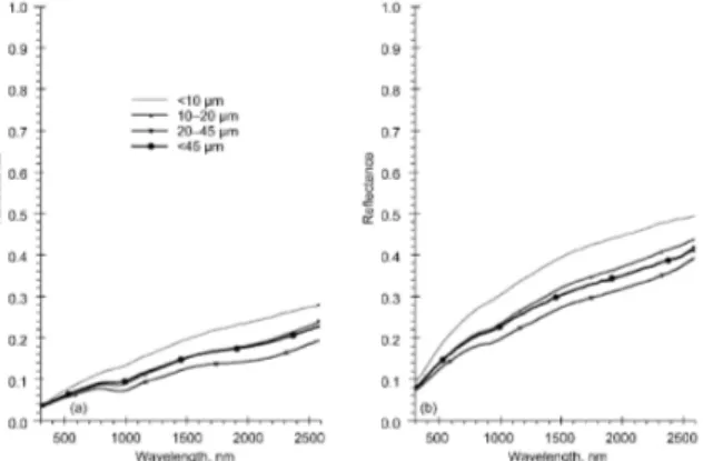
Chemical composition and reflectance are values reported in the NASA documents on the certifi-cation of NU-LHT-2M and were assumed correct and considered only to evaluate an initial theoret-ical feasibility of the process with the given laser wavelength and power.
Figure 2: Reflectance of Moon Sample of mare soil (a) and highlands soil (b) from Apollo mis-sions sorted by grain size (Data from NASA research [7])
Using a 250W fiber laser at 1070nm proved in previous works capable to efficiently melt the JSC-1A simulant and produce solid 3D-printed objects working at about 20% of its maximum power; the values of reflectance at the desired wavelength are not enough dissimilar to justify the choice of an-other type of laser so it was not changed in this work. At the same time the chemical composition of the two simulants should differ since they are de-signed to be similar to the soil of different regions of the Moon but the knowledge of some of the major components of the powder offers possible hints on the fine adjustments to apply for a better process. Table(1) reports the mass percentages of various elements present in the NU-LHT-2M simulant and compares them to that of actual Moon soil samples returned to Earth during the Apollo missions.
Apollo 16 NU-LHT-2M SiO2 45.09 46.60 T iO2 0.56 0.115 Al2O3 27.18 21.55 F eO 5.18 5.65 M nO 0.065 0.09 M gO 5.84 9.50 CaO 15.79 12.60 N a2O 0.47 0.965 K2O 0.11 0.12 P2O5 0.12 0.07 Cr2O5 0.107 0.12 S 0.064 -LOI∗ - 2.74
Table 1: Chemical composition comparison be-tween NU-LHT-2M and Apollo 16 samples Note: *LOI, lost in ignition volatiles
3. Printing process
After defining the most relevant properties of the powder, the printing process was tested using a small size SLM prototype capable to operate either in soft vacuum or inert atmosphere. The choice to use the laser in an oxygen deprived environment (Ar atmosphere was used) was made in order to avoid the combustion of small particles and the consequent damages that the process could cause to some of the most sensible components of the machine. The machine flexibility was exploited in terms of the material used as substrate for the printing process. The possibility to interrupt and adjust the process during operation was an extremely valuable resource in order to obtain good results. The machine main parameters are reported in Table (2).
Parameter Value
Power (max) 250W
Wavelength 1070 nm
Laser spot size 75 µm
Scanning speed 50-250 mm/s
Hatching space 75-150 µm
Layer thickness 150-250 µm
Table 2: SLM machine parameters values used in the tests
The first tests were based on a wide range of parameters that offered a general knowledge on the material response to the processing with the laser source. Power, scanning speed, hatching space, thickness of the layers and focal point offset were tested in various combination to evaluate which set of parameters returned the best results but the process didn’t return any positive results due to lack of adhesion of the printed material to the substrate. The steel plate used showed extremely low wettability to NU-LHT-2M as can be seen by the balling effect visible in Fig.(3) but the problem was faced selecting other materials, including various metal alloys that showed the same balling effect; the best results were obtained with a ceramic substrate.
The susbtrate chosen for the test is a refractory clay commonly used for high temperature oven or kiln, thus capable to withstand the large amount of thermal energy exchanged during the process and, at the same time, having a chemical composition closer to that of the powder used. The possibility of coating the metal substrate with a thin layer of the NU-LHT-2M was discarded due to higher costs and difficulties of implementation in the process.
Figure 3: Balling effect on the steel susbtrate
Once the substrate was substituted with the refrac-tory clay plate, the experiments proceeded without issues related to the adhesion of the powder, but the laser power was reduced drastically to avoid damages to the ceramic substrate. After investi-gating the possible combination of parameters, the best results in terms of consistency of the printed part quality and precision were obtained with the parameters reported in Table 3.
Laser Power 50 − 60 W Laser Spot 50 − 300 µm Scanning Speed 100 − 200 mm/s Layer Thickness 150 µm Hatching Space 75 µm Duty Cycle 100%
-Table 3: Final set of parameters chosen for the printing of NU-LHT-2M
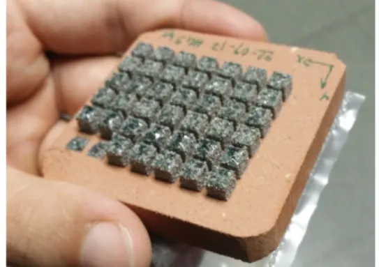
The printed objects were small cubes with size of 5mm arranged on the substrate in a checkerboard pattern to separate the results depending on the parameters used for each of them. During the final prints, the position linked to each parameters set was random in order to avoid any interference on the quality related to geometry parameters. The results were in no way affected by the geometry but in one run, during which the substrate was slightly misaligned and the growth of the pieces was not uniform across the plate.
4. Results
After the range for each parameter was defined, a set of printed samples were produced to test the material mechanical properties. The first step af-ter removing the pieces from the substrate was to measure each of them to grant repeatability of the tests without introducing any correction factor. Af-terwards, the pieces were put in a thermovacuum chamber to remove any volatile component trapped
Figure 4: Printed parts obtained with the final set of parameters
inside the molten powder. The procedure adopted was described in the ECSS normative as the bake-out processing of parts to be used in the bake-outgassing tests for space components. The printed objects were exposed to T≥ 125◦C and P≤ 1Pa for a to-tal time of 16 hours to ensure that all the volatile components were removed.
The first test was performed on a mixed batch of samples to evaluate the surface hardness through Vickers microindentation following the procedure described in the ASTM [8]. In order to have smooth parallel surfaces to work on, the parts were enclosed in a resin cast which also offered a better support during the test. The pieces were polished using increasing sandpaper grit, from P60, to P120 and finished with P320.
Figure 5: Specimens in the resin cast
The specimens were tested in a Leica VMHT30A, set to 500gf load with a 15s dwell time repeating the analysis for each sample in 10 discrete position on its surface to avoid any sort of bias in the measurements. The average result for the surface hardness of the material for each specimen is reported in Table 4 showing results in the order of the hardness of common silica glass as obtained in the researches involving JSC-1A.
Sample N. HV A50200 679.28 A50225 680.93 A55200 669.51 A55225 698.39 A60200 690.57 A60225 661.75 B50200 673.51 B50225 638.16 B55225 748.54 B60200 710.43 B60225 685.43
Table 4: Average hardness for the different samples
One of the lacking information on the 3D-printing with Moon regolith simulant is the com-pressive strength of the material, which in this study is introduced but requires further develop-ments to return precise results applicable to the actual building process with 3D-printed moondust. In this research the strength was measured using a load cell coupled to a hydraulic press imposing a displacement value on the moving head. The ma-terial showed fragile behaviour, as expected for ce-ramics, and a strength comparable to that of con-crete, reaching average yielding stresses as reported in Table 5 σY[M P a] A50200 16.6 A50225 31.43 A55200 22.3 A55225 29.55 A60200 14.34 A60225 22.24
Table 5: Yield Stresses
One interesting phenomenon was observed in ev-ery run of the compressive strength test, during which the material started yielding but didn’t col-lapse as expected and, instead, was compacted. The internal crevices created during the melting and rapid cooling of the material offer an energy relief thanks to the inner structure that can be ex-ploited as a ballistic protection system, for example against impact with small objects and micromete-orites, typical of the Moon environment and cur-rently one of the potential hazards that could be found on the lunar surface during the colonization process.
5. Conclusions
This research proved the feasibility of 3D-printing with highlands regolith simulant NU-LHT-2M, addressing one of the missing point of previ-ous researches, limited to the use of mare regolith
simulants. The values obtained shows that the be-haviour of the different simulants is similar under many point of view, including also the mechani-cal properties obtained during the analysis of the printed parts. This work is a starting point for a more extensive research on the properties of the ma-terials used and the capabilities of the SLM technol-ogy applied to space exploration and colonization. Next steps in this work will comprise thermal analy-ses and radiation shielding properties investigation on printed objects, together with an increase in the TRL of the machine used which could be scaled and adapted to be space certified and approved for a flight demonstration or even an IOD mission. References
[1] A. Goulas, J. G. P. Binner, R. A. Har-ris, and R. J. Friel, “Assessing extraterres-trial regolith material simulants for in-situ resource utilisation based 3D printing,” Ap-plied Materials Today, Vol. 6, 2017, pp. 54–61, 10.1016/j.apmt.2016.11.004.
[2] M. Fateri and A. Gebhardt, “Process Parame-ters Development of Selective Laser Melting of Lunar Regolith for On-Site Manufacturing Ap-plications,” International Journal of Applied Ceramic Technology, Vol. 12, jan 2015, pp. 46– 52, 10.1111/ijac.12326.
[3] A. Goulas and R. J. Friel, “3D printing with moondust,” Rapid Prototyping Jour-nal, Vol. 22, No. 6, 2016, pp. 864–870, 10.1108/RPJ-02-2015-0022.
[4] A. Goulas, R. A. Harris, and R. J. Friel, “Additive manufacturing of physical assets by using ceramic multicomponent extra-terrestrial materials,” Additive Manufactur-ing, Vol. 10, No. April, 2016, pp. 36–42, 10.1016/j.addma.2016.02.002.
[5] M. Fateri, R. A. Gabrielli, A. Grossmann, S. Fasoulas, A. Großmann, P. Schnauffer, and P. Middendorf, “Additive Manufacturing of Lunar Regolith for Extra-terrestrial Industry Plant Additive Manufacturing of Lunar Re-golith for Extra-terrestrial Industry Plant,” No. November, 2015.
[6] M. Fateri, A. Gebhardt, and A. X. Lester Bok, “Investigation of the Feasibility of Mo-bile Additive Manufacturing Systems Powered by Photovoltaic Modules,” Additive Manufac-turing (AM): Emerging Technologies, Applica-tions and Economic ImplicaApplica-tions, No. October 2016, 2015, pp. 111–123.
[7] J. R. Gaier, K. W. Street, and R. J. Gustafson, “Measurement of the Solar Absorptance and Thermal Emittance of Lunar Simulants,” 40th International Conference on Environmental Systems, No. August 2010, 2010, pp. AIAA– 2010–6025.
[8] W. Conshohocken, “Standard Test Method for Vickers Indentation Hardness of Advanced Ce-ramics 1,” Test, No. March, 2003, pp. 1–10, 10.1520/C1327-08.2.
[9] A. G. Demir, P. Colombo, and B. Previ-tali, “From pulsed to continuous wave emis-sion in SLM with contemporary fiber laser sources: effect of temporal and spatial pulse overlap in part quality,” International Journal of Advanced Manufacturing Technology, 2017, pp. 1–14, 10.1007/s00170-016-9948-7.
[10] A. Goulas, D. Southcott-Engstrom, R. J. Friel, and R. A. Harris, “Investigating the addi-tive manufacture of extra-terrestrial materi-als,” 2016 Solid Freeform Fabrication Sympo-sium Proceedings (SFF Symp 2016), No. Au-gust, 2016, pp. 2271–2281.
[11] F. Pahlevani, R. Kumar, N. Gorjizadeh, R. Hossain, S. T. Cholake, K. Privat, and V. Sahajwalla, “Enhancing steel prop-erties through in situ formation of ultra-hard ceramic surface,” Scientific Reports, Vol. 6, No. November, 2016, p. 38740, 10.1038/srep38740.
[12] A. Grossmann and R. A. Gabrielli, “Overview of the MultiRob 3D Lunar Industrial Develop-ment Project,” No. November, 2015.
[13] X. D. Kestelier, “Lunar Outpost Design,” 2015, pp. 3–6.
[14] R. P. Mueller, L. Sibille, P. E. Hintze, T. C. Lippitt, J. G. Mantovani, M. W. Nugent, and I. I. Townsend, “Additive Construction Using Basalt Regolith Fines,” Earth and Space 2014, 2015, pp. 394–403, 10.1061/9780784479179.042.
[15] B. Roland, A. G. Abrielli, J. M. Athies, A. G. Roßmann, G. H. Erdrich, S. F. Asoulas, P. S. Chnauffer, P. M. Iddendorf, M. F. Ateri, and A. G. Ebhardt, “Space Propulsion Considera-tions for a Lunar Take Off Industry Based on Regolith,” No. July 2015, 2015, pp. 2–7. [16] B. Roland, A. G. Abrielli, J. S. Eelmann, A. G.
Roßmann, G. H. Erdrich, S. F. Asoulas, P. S. Chnauffer, P. M. Iddendorf, M. F. Ateri, and
A. G. Ebhardt, “System Architecture of a Lu-nar Industry Plant Using Regolith,” No. July 2015, 2015, pp. 1–8.
[17] G. Cesaretti, E. Dini, X. De Kestelier, V. Colla, and L. Pambaguian, “Building com-ponents for an outpost on the Lunar soil by means of a novel 3D printing technology,” Acta Astronautica, Vol. 93, 2014, pp. 430–450, 10.1016/j.actaastro.2013.07.034.
[18] V. Colla, E. Dini, G. Cesaretti, X. De Keste-lier, and L. Pambaguian, “Monitoring con-cepts for a 3D printer applied to build a human outpost on the moon,” Proceedings - UKSim-AMSS 16th International Conference on Com-puter Modelling and Simulation, UKSim 2014, 2014, pp. 206–210, 10.1109/UKSim.2014.50. [19] M. Fateri, A. Gebhardt, and M.
Khos-ravi, “Experimental Investigation of Selec-tive Laser Melting of Lunar Regolith for In-Situ Applications,” Proceedings of the 2013 ASME International Mechanical Engineering Congress and Exposition, No. November, 2013, 10.1017/CBO9781107415324.004.
[20] A. Scott Howe, B. Wilcox, C. McQuin, J. Townsend, R. Rieber, M. Barmatz, and J. Leichty, “Faxing Structures to the Moon: Freeform Additive Construction Sys-tem (FACS),” AIAA SPACE 2013 Con-ference and Exposition, 2013, pp. 1–23, 10.2514/6.2013-5437.
[21] M. Fateri, J. S. H??tter, and A. Gebhardt, “Experimental and Theoretical Investigation of Buckling Deformation of Fabricated Objects by Selective Laser Melting,” Physics Procedia, Vol. 39, No. October 2016, 2012, pp. 464–470, 10.1016/j.phpro.2012.10.062.
[22] V. Krishna Balla, L. B. Roberson, G. W. O’Connor, S. Trigwell, S. Bose, and A. Bandy-opadhyay, “First demonstration on direct laser fabrication of lunar regolith parts,” Rapid Pro-totyping Journal, Vol. 18, No. 6, 2012, pp. 451– 457, 10.1108/13552541211271992.
[23] J. Miller, L. Taylor, C. Zeitlin, L. Heilbronn, S. Guetersloh, M. DiGiuseppe, Y. Iwata, and T. Murakami, “Lunar soil as shielding against space radiation,” Radiation Measure-ments, Vol. 44, No. 2, 2009, pp. 163–167, 10.1016/j.radmeas.2009.01.010.
[24] R. N. Grugel and H. Toutanji, “Sulfur ”concrete” for lunar applications - Subli-mation concerns,” Advances in Space Re-search, Vol. 41, No. 1, 2008, pp. 103–112, 10.1016/j.asr.2007.08.018.
[25] C. A. McLemore, J. C. Fikes, C. A. Darby, J. E. Good, and S. D. Gilley, “Fabri-cation capabilities utilizing in situ materi-als,” Space 2008 Conference, 2008, pp. 1–6, 10.2514/6.2008-7854.
[26] J. Miller, L. Taylor, M. DiGiuseppe, L. Heil-bronn, G. Sanders, and C. Zeitlin, “Radiation Shielding Properties of Lunar Regolith and Re-golith Simulant,” NLSI Lunar Science Confer-ence, 2008, pp. 4–5.
[27] J. P. Kruth, G. Levy, F. Klocke, and T. H. C. Childs, “Consolidation phenomena in laser and powder-bed based layered manufactur-ing,” CIRP Annals - Manufacturing Tech-nology, Vol. 56, No. 2, 2007, pp. 730–759, 10.1016/j.cirp.2007.10.004.
[28] B. Khoshnevis, D. Hwang, K.-T. Yao, and Z. Yah, “Mega-scale fabrication by contour crafting,” Int. J. Industrial and Systems En-gineering, Vol. 1, No. 3, 2006, pp. 301–320, 10.1504/IJISE.2006.009791.
[29] B. Khoshnevis, M. Bodiford, K. Burks, E. Ethridge, D. Tucker, W. Kim, H. Toutanji, and M. Fiske, “Lunar Contour Crafting - A Novel Technique for ISRU-Based Habitat De-velopment,” 43rd AIAA Aerospace Sciences Meeting and Exhibit, No. January, 2005, pp. 1– 12, 10.2514/6.2005-538.
[30] L. A. Taylor and T. T. Meek, “Microwave Sintering of Lunar Soil: Properties, Theory, and Practice,” Journal of Aerospace Engi-neering, Vol. 18, No. 3, 2005, pp. 188–196, 10.1061/(ASCE)0893-1321(2005)18:3(188). [31] M. Fateri and M. Khosravi, “On-site
Addi-tive Manufacturing by SelecAddi-tive Laser Melt-ing of composite objects,” Science (New York, N.Y.), Vol. 305, No. June, 2004, pp. 842–845, 10.1126/science.3050842.
[32] J. Lawrence and L. Li, “Carbon steel wet-tability characteristics enhancement for im-proved enamelling using a 1.2 kW high power diode laser,” Optics and Lasers in Engi-neering, Vol. 32, No. 4, 1999, pp. 353–365, 10.1016/S0143-8166(00)00007-5.
[33] European Cooperation for Space Standardiza-tion, “Space product assurance: Thermal vac-uum outgassing test for the screening of space materials,” No. November, 2008, pp. 1–45. [34] European Cooperation for Space
Standardiza-tion, “Space product assurance: Thermal vac-uum outgassing test for the screening of space materials,” No. November, 2008, pp. 1–45.
[35] ECSS, “Space Product Assurance - Thermal testing,” Structure, No. April, 1996, pp. 1–25, ECSS-Q-ST-30-11C Rev 1.
[36] J. P. Williams, D. A. Paige, B. T. Green-hagen, and E. Sefton-Nash, “The global surface temperatures of the moon as mea-sured by the diviner lunar radiometer exper-iment,” Icarus, Vol. 283, 2017, pp. 300–325, 10.1016/j.icarus.2016.08.012.
[37] D. B. J. Bussey, J. A. McGovern, P. D. Spudis, C. D. Neish, H. Noda, Y. Ishihara, and S. A. Sørensen, “Illumination conditions of the south pole of the Moon derived using Kaguya topography,” Icarus, Vol. 208, No. 2, 2010, pp. 558–564, 10.1016/j.icarus.2010.03.028. [38] E. Mazarico, G. A. Neumann, D. E. Smith,
M. T. Zuber, and M. H. Torrence, “Il-lumination conditions of the lunar polar regions using LOLA topography,” Icarus, Vol. 211, No. 2, 2011, pp. 1066–1081, 10.1016/j.icarus.2010.10.030.
[39] X. Li, S. Wang, Y. Zheng, and A. Cheng, “Es-timation of solar illumination on the Moon : A theoretical model,” Vol. 56, 2008, pp. 947–950, 10.1016/j.pss.2008.02.008.
[40] ASTM, E2584-14 Standard Practice for mal Conductivity of Materials Using a Ther-mal Capacitance (Slug) Calorimeter.
[41] D. B. Stoeser, D. L. Rickman, and S. A. Wil-son, “Design and Specifications for the High-land Regolith Prototype Simulants NU-LHT-1M and -2M,” Nasa Tm, No. 2010–216438, 2010, p. 24p.