3DSlicer Module To Perform Registration: An
Intraoperative Situation*
Barbosa, Roberto M.
1; Serrador, Luís
1; Santos, Bruno
2; Silva, M. V.
2; De Momi, Elena
3; Santos, Cristina
4 1University of Minho, Department of Electronic Engineering, Guimarães, Portugal, {a68363, a68393}@alunos.uminho.pt2Orthopaedics department, Hospital de Braga, Braga, Portugal
3Bioengineering Department, Politecnico di Milano University, Milan, Italy, [email protected] 4University of Minho, CMEMS/DEI, Guimarães, Portugal, [email protected]
Abstract — Computer-assisted surgeries (CAS) had a great
improvement in last decades. Nowadays, a lot of surgeries are performed with the aid of a tracking system and robotic devices. It is important to ensure the success of the intervention when it is performed with this kind of technologies. One of the most important steps in CAS is registration that allows the surgeon to track his instruments and to know what he is doing when the surgical field of view is limited. A 3DSlicer module is presented to perform the registration procedure quickly and intuitively, since this step must be made as fast as possible. This module allows the surgeon to collect points from the patient’s anatomical structure that he is working on in order to perform a point-to-point registration followed by the surface registration based on iterative closest point algorithm. Thus, it is possible to match the coordinates system of the 3DSlicer model and the coordinates system of operating room so that the preoperative 3D model on the software and the tracking of the surgical instruments used during the surgery are synchronized. An example using a sheep skull and a tracking system is described and the results of the registration are shown. The registration procedure is evaluated calculating the mean distance from the landmarks from patient’s anatomical structure and the surface of the 3DSlicer model. The value obtained was 0,29 mm RMS which indicates that the module could be a good option to perform the registration in a surgical room.
Keywords — Computer-assisted surgey; Registration; Optical tracking system
I. INTRODUCTION
Surgical procedures have undergone a great evolution. In the last two decades, the traditional methods have been replaced by some recent procedures and strategies that make the surgeries easier to perform and reduce the recovery time of the patient.
There are a lot of surgeries such as the thoracic, abdominal, orthopaedic and neurosurgeries that have been improved with some innovative techniques. Advances in technology and computing have allowed these types of surgeries to become less invasive and more accurate [1][2].
A computer-assisted surgery (CAS) module allows the surgeon to get real-time feedback about the performed surgical actions using information provided through a virtual scene on a display device. The CAS includes approaches that use tracking systems and robotic devices to increase the accuracy and also to provide a solution when the field of view of the surgeon is reduced [2]. Two of the most used robotic devices are the da
Vinci surgical system that is used in abdominal and thoracic surgeries and the RIO system that is used in orthopaedic surgeries.
The da Vinci surgical system (Intuitive Surgical Inc, CA) is a teleoperated system that only relies on the surgeon’s direct input through the master controller. It is composed by four arms for tool handing (including the camera) and dual console control for cooperative surgery or training. This system was an important improvement in abdominal and thoracic surgery since it is minimally invasive [3].
The RIO system (MAKO Surgical Corp., US) is a robotic arm to use in orthopaedic surgeries that revolutionized the hip and knee replacement. Based on a preoperative plan the surgeon is guided by a virtual scene and the robotic arm prevents the surgeon to resect some wrong parts of the bone. At the end, the implants fit perfectly on the patient’s bone. It avoids additional problems during the recovery and ensures the success of the surgery [4].
These are two examples that show to the scientific community the benefits of one assisted surgery once their outcomes are proving the huge potential of these approaches [3][4].
In orthopaedics and neurosurgery, the systems that are chosen are preferably to employ a navigated surgery. Using a preoperative image (e.g., Computed Tomography (CT), Magnetic Resonance Imaging (MRI)) of the patient the surgeon can plan the surgery and define the tasks accurately, resulting in superior precision [3].
This paper presents one way to perform the registration in the intraoperative situation in an easier and faster way. 3DSlicer software contains the necessary modules to perform the registration but this study aims to achieve a faster procedure with the creation of a module in this software that allows the surgeon to perform all the procedures fluently in this module. Also, this paper aims to perform a study of the interference of the selected fiducials to perform the point-to-point registration in the registration procedure outcome.
In order to achieve a better comprehension, during this paper, the preoperative 3D model performed in 3DSlicer using the CT scans is mentioned as virtual model and the respective patient’s anatomical structure in the intraoperative situation as physical model.
II. REGISTRATION
During orthopaedic and neurosurgeries, the surgeon has to move the body structures that he is treating. In this case a navigated surgery is needed to track what the surgeon is doing and help him performing the surgery [5]. An accurate registration between the patient and the preoperative images must be made and it would allow the surgeon to move the patient during the surgery to a more convenient position and the surgical plan is adjusted accordingly [5].
A navigation system needs to display the current tool location in the coordinate system of the virtual scene. In general, this coordinate system differs from the one in which the navigator operates intraoperatively and the mathematical relationship between both coordinate spaces needs to be determined. When preoperative images are used to create a virtual model of the structure, this step is made interactively by the surgeon. This is called the registration, or matching [2].
In order to achieve the best result, the registration is divided in two steps: point-to-point (or paired-point) registration and surface registration. The point-to-point registration is simple; it consists in matching two sets of points. One of the sets is defined preoperatively in the virtual model using the computer mouse, while the corresponding set of points is collected on the anatomical structure that the surgeon is working on, using a pointer tool. Although point-to-point registration is easy to solve mathematically, it depends on an optimal selection of the points and the exact identification of the associated pairs which is error-prone leading to a low accuracy of the resultant registration. Because of that, it is complemented with surface registration after [2].
The surface registration will match the virtual model with the physical one. This method uses the virtual model and a new set of fiducial points of the physical structure that have to be collected intraoperatively by the surgeon using the pointer tool.
Cutter et al [5] compares two popular methods of surface registration: iterative closest point (ICP) and coherent point drift (CPD) algorithms. It was verified that ICP results in a better registration [5]. The ICP algorithm consists in pairing each point collected from the physical structure with the nearest point of the virtual model (points in the virtual model can be paired to more than one point of the physical structure), then estimating the transformation that will most reduce the mean square of the distances between pairs. The points are then re-paired and the process is repeated until the stopping conditions are met [5]. This algorithm gives the transformation from the points of the physical model to the virtual model.
The registration must be made as fast as possible without losing to much time. In this paper, a module on 3DSlicer is presented where all the steps of the registration process can be made. It will result in a better and easier user experience once it has all steps listed and ordered to improve the workflow.
III. MATERIALS AND METHODS
A. Equipments
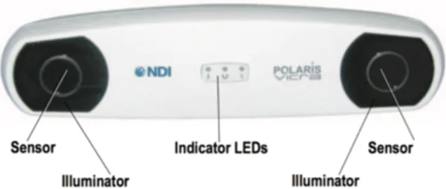
As described above, to perform the registration it is necessary to use an optical system. In this study, it was used the Polaris Vicra system from Northern Digital Inc. (NDI) [6]. This was the chosen equipment due to its accuracy of 0.25 mm RMS which ensures positive outcomes in the registration procedure. On the other hand, the workspace of the optical tracking system must ensure that it is able to achieve the tracking of the tools during all procedures of the surgery. At this point, it is necessary to take into account that this system is limited to 1,34 meters of depth and every single application of this system has to be study to infer about its performance [6].
As a measurement equipment, the Polaris Vicra system is a powerful system to measure the 3D positions of specific tools that are recognized by infrared light. The brain of this equipment is the Position Sensor, which is illustrated in figure 1, and it contains two sets of arrays of infrared light, called illuminators, and two sensors that collect the Infrared light from the markers of the tool. Each tool is characterized by a set of four markers positioned in well specific locations allowing the recognition of the tip’s tools. There are two types of markers that can be attached to the tools. The passive markers are coated in order to reflect the infrared light from illuminators and then, this reflected light is captured by sensors. On the other hand, the active markers are able to emit infrared light to sensors by incorporated infrared Light Emitting Diodes (IREDs) markers. In this study, it was used a passive tool provided by NDI.
It is possible to design a specific tool in order to address a specific purpose. The geometry of the tool must be characterized as well as the markers arrangement. In a file definition tool created by NDI 6D Architect software, all this information is declared and this file allows the Position Sensor to calculate the transformations during the tool movement and in this way, it is performed the tip’s tool tracking. The host computer with a specific software is the necessary equipment to perform the real-time tracking of the selected tool, after connecting with Polaris Vicra system and its file definition tool.
The software used in this project was 3DSlicer [7], an open source software that has a wide application in the computer-aided surgery projects. This software provides a lot of pre-defined modules and allows the user to perform his own module using specific functions for the desired tasks [8]. This functionality was the reason to start this project. It is an important feature of this software to improve the user experience allowing an easier and more intuitive utilization of the 3DSlicer’s functions for example with an implementation of a Graphical User Interface (GUI) as performed during this work. The exams used to plan a surgery, such as MRI and CT, can be easily read using this software since it incorporates a DICOM converter. Thus, the 3D reconstructions of the anatomical structures in the exams are made to a better visualization and a more precise pre-operative plan. To achieve these 3D reconstructions, the software provides a set of modules that are suitable for that. The image must be segmented to select the desired structure from the exam’s content. The editor module helps the user to create the 3D model with a set of tools that allows to select thresholds, regions of interest and to delete the undesired areas [9].
In this study, once it aims to perform a module to assist the registration process it was used one CT exam of a sheep head and it was built a 3D model of its skull on a 3D printer. This way, the two models, the virtual one in 3DSlicer obtained by CT, and the physical model have exactly the same dimensions and thus it is possible to validate the registration method comparing the points collected from the physical model with the virtual. Specifically, it is determined an accuracy value to specify the proposed registration.
B. How to do the registration with 3DSlicer modules
There are four modules on 3DSlicer that can be used to perform the registration: Collect Fiducial, Fiducial Registration Wizard and Fiducials-Model Registration which belong to the extension IGT and the Transforms module.
The first module that is used after connecting the tool to the 3DSlicer is the Collect Fiducial module. This module can collect the points that the surgeon wants to collect from the physical model. There is a button that every time it is pushed, a fiducial is placed on the coordinates where the tool tip is in the virtual scene.
After that, the point-to-point registration is performed using the Fiducial Registration Wizard module. This module uses the fiducials that the surgeon collected before and the points that the surgeon selected preoperatively. The fiducials are chosen in the same sequence, i.e., the first fiducial in one of the two sets of points corresponds to the first fiducial on the other set, and so on. The goal is to match the two sets of points; however, this registration is not enough to get a good resultant match of both bones (virtual and physical). The output of the module is a transformation matrix that can transform the first set of points into the second set. To apply it to the model the Transforms module is used. This transformation must be in the hardest way in order to update the model’s data. If it is not done the model
is displayed in the right position on the 3D view but the data is not updated.
To perform the surface registration using the ICP algorithm it is necessary to collect more fiducials to achieve a better registration once a higher number of collected points leads to a better matching between the points and the surface of the virtual model. It must be taken into account that these points in an intraoperative situation are difficult to collect by the surgeon, so it is necessary to establish a compromise. In this case, 10 fiducials points were collected to perform the surface registration. The surgeon must use again the Collect Fiducial module and collect the new points. After collecting the points the Fiducials-Model Registration module is used. It has two inputs – the fiducials collected and the model after the point-to-point transformation – and the output is a transformation matrix that should match the fiducials collected from the physical model with the virtual model. To obtain the right position of the module, the calculated transformation has to be applied to the model obtained by point-to-point registration using the Transforms module again.
The registration procedure using the 3DSlicer modules is a hard task but as it was shown it cannot be done in a fast way since there is the need to use several interfaces and modules to do it. The registration has to be done quickly and toggling between modules is not the best way. One intuitive module which could be used to perform registration could make it easier and it would be a great improvement in terms of time and facility of use.
C. Module Creation
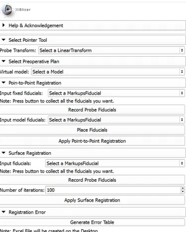
The module was created in Python and MATLAB® (The MathWorks Inc., MA). The Graphic User Interface (GUI) and functionality was created in Python and it consists in five sections. Figure 2 shows the developed GUI Module with all mentioned sections expanded. There, it can be seen the entire workflow of the registration and also the disposition of the elements in the module.
The first section (‘Select Pointer Tool’) allows the user to choose the tool transform used to collect the points from the physical bone. The second section (‘Select Preoperative Plan’) is used to select the virtual model that the user wants to match with the physical one, usually this model is obtained using preoperative images (CT or MRI) of the physical bone.
The registration procedure starts in the third section (‘Point-to-Point Registration’). Here the user can collect the points of the physical bone using the pointer tool and whenever the button ‘Record Probe Fiducials’ is pushed the point appears in the virtual coordinate system and is collected to the fiducials list chosen on the box above. After that, the user can place virtual fiducials on the virtual model that correspond to the points collected before with the pointer tool. Clicking in the ‘Place Fiducials’ button it is possible to place the fiducial and it is collected in the fiducials list that is selected in the box above that button. At the end of this section there is the ‘Apply
Point-to-Point Registration’ button that applies the point-to-point registration and applies the transformation to the virtual model.
The fourth section (‘Surface Registration’) corresponds to the surface registration based on the ICP algorithm. The user can collect the fiducials from physical model using a ‘Record Probe Fiducials’ and they are stored in the fiducials list selected on the box of the section. Since the ICP algorithm is an iterative method it is necessary to have a maximum number of iterations as a stop condition if the algorithm does not converge to a good solution and it also can be chosen. The ‘Apply Surface Registration’ button implements the ICP algorithm using the virtual model resultant from the previous section (after point-to-point registration) and the fiducials collected in this section. The transformation is then applied to the model and it is the last step of registration procedure.
A fifth section (‘Registration Error’) contains a function that was created in MATLAB® to evaluate the final model position and orientation. The error was calculated based on the last fiducials collected from the physical bone (those that were used on ICP algorithm) and the resultant virtual model from the registration. The parameter used was the mean distance between each fiducial position and the nearest point of the model. When the ‘Generate Error Table’ button is pushed, the Slicer software opens a Matlab file that generates an Excel file to posterior analysis of the procedure performed with this module.
Fig. 2. Developed GUI Module in 3DSlicer with all registration procedures.
D. An example of the module’s workflow
This section of the paper shows how the module works. A CT was made on a sheep head and a 3D virtual model was created on 3DSlicer using the CT scans. This 3D reconstruction normally is performed in the preoperative plan of the surgery. As mentioned, the physical model used was a printed skull of a sheep based on the CT made before. Both models used to perform registration and the passive tool from NDI are shown in figure 3.
Initially, the 3D virtual model is placed in a random position and orientation in the coordinate system of 3DSlicer and, when connected to 3DSlicer, the Vicra passive tool is shown in the coordinate system of 3DSlicer with the transform matrix given by the optical tracking system. So, in the virtual environment we have the visualization of the real pointer tool.
Thus, the pointer tool when is touching in the physical model cannot reach the virtual model and the goal of registration is to determine the spatial relationship between the real bone and its CT.
Firstly, in each performed trial, four points were collected from the physical model and the corresponding fiducials were placed on the virtual model in order to perform the point-to-point registration. It is relevant to refer that the order of the collected points it is important to achieve the registration, as mentioned above. At this moment, we can touch different points of the physical model and check if it corresponds to the same point on the virtual. However, figure 4 shows that the pointer tool seems to be under the virtual model and what happen is that we are sliding the tool on the surface of the physical model.
To place the virtual model on the same position and orientation as the physical one it is necessary to perform the surface registration using the fourth section of the module. More points are collected from the physical model to perform the last step of registration as mentioned above, in this case 10 fiducials were used to perform this step. In figure 5 it is possible to see the virtual model before and after the surface registration. This last one is identified with the gray color.
After the surface registration, the virtual model match with the physical one. Although the registrations seem to match perfectly both models it is not true. There is always an associated error when the registration is performed and it will be discussed on the ‘Results’ section of this paper.
Fig. 4. Localization of the pointer tool after point-to-point registration.
Fig. 5. The final result of the registration (gray color) comparing with the model obtained only by point-to-point registration, in the third section of the module.
E. Trials with different reference points in point-to-point registration
In order to understand the influence of the chosen reference points in the point-to-point registration, four trials were made with different references and performing the surface registration in the same way. Account must be taken in the choice of these references. To approximate as much as possible these procedures to a surgical situation we must know that collecting these points is a meticulous task for the surgeon. To achieve a good point-to-point registration the points selected on the virtual model, in the pre-operative plan, and the collected points at the operating room must be the most coincident possible and, as we know, it is difficult to the surgeon to know the exact position once the skin and muscle of the patient do not allow a better visualization. So, besides reducing the number of reference points to the minimum required, at least 3 to be possible achieve the right position and orientation, these points should be placed in the adequate places also, to facilitate this task to the surgeon.
Fig. 6. Trials with different reference points in point-to-point registration: A) situation 1; B) situation 2; C) situation 3.
So, in this study were performed four trials choosing different initial references to start the point-to-point registration. It should be considered that as the used model is from an animal there are no specific references in advance. So, the references were placed in some recognizable locals to make sure that it would be possible to collect them on the physical model with the tool tip. The number of references were four in three situations and six for the last one. The first three situations are presented with the virtual models and the references placed in the figures 6A, 6B and 6C, respectively.
A
B
Finally, the last situation was made with all the markers presented in the previous situations. So, six markers were placed to perform the point-to-point registration in this situation.
All the situations were evaluated and the relevant outcomes were presented on the next section.
IV. RESULTS
To validate the module procedures and the outcome from this registration method was performed a study of all trials evaluating the accuracy of them.
The error was calculated as the mean distance from all the fiducials collected to perform the surface registration to each nearest point of the virtual model.
Analyzing table I, it is possible to confirm that the increase of references to perform the point-to-point registration do not leads to a better registration after the final procedure, surface registration. The best outcome was obtained in the first situation and the reason for that may depend on the anatomy of the region where the references were placed. It is possible to verify in the previous figures that the references in situation 1 are more defined and it is better to collect these points in the exact position with the pointer tool.
Regarding the accuracy obtained in the registration procedure we will evaluate the situation that obtained the better outcome, the situation 1 as referred previously. So, it is important to note that the equipment used in these experiments Polaris Vicra system has an accuracy of 0.25 mm RMS. The evaluation of the registration procedure must take into account this value. The error obtained in this situation was 0.29 mm RMS which is a very close value of the accuracy of the used system. So, this leads to the validation of the procedures made with the presented module.
TABLE I. TABLE WITH THE COMPARISON OF ERRORS
Situation Evaluated Parameters (mm)
Mean Distance STD RMS Min Min
1 0.2719 0.1130 0.2923 0.5261 0.0990 2 0.4698 0.2063 0.5089 0.9281 0.1944 3 0.3254 0.1249 0.3463 0.6580 0.2149 4 0.2941 0.1251 0.3175 0. 5859 0.1768
V. CONCLUSIONS
The navigated surgery leads to an improvement of accuracy in surgeon procedures. It is important to expand this field to provide more precise interventions.
The module created allows the user to perform the registration without toggle between different modules and is very intuitive. This kind of application may decrease the time
that is spent during this procedure and the registration continues to be successful.
During this study were made some trials about the acquisition of the references pre-operatively and the outcomes indicate that the most important thing to be taken into account during the plan is to know the barriers to achieve those points during the surgery and also if the anatomy of this region has some characteristics that turn it easier to identify them. Due to the difficulty to achieve those landmarks, the surface registration leads to an improvement of the outcome as it was shown during this paper.
In these trials, the sheep skull was held to perform the registration procedure. In a real situation is not guaranteed that the bone of the patient does not move. In order to allow the movement of the bone during the registration, one reference should be placed to achieve the landmarks in relation to this one.
It was possible to check the workflow of registration with the present module and the results obtained indicate that it could be an easier and faster way to perform the registration with the great accuracy of 3DSlicer functions.
REFERENCES
[1] A. Kumar e B. Asaf, «Robotic thoracic surgery: The state of the art», J. Minim. Access Surg., vol. 11, n. 1, pp. 60–67, 2015.
[2] G. Zheng e L. P. Nolte, «Computer-Assisted Orthopedic Surgery: Current State and Future Perspective.», Front. Surg., vol. 2, n. December, p. 66, 2015.
[3] M. Hoeckelmann, I. J. Rudas, P. Fiorini, F. Kirchner, e T. Haidegger, «Current capabilities and development potential in surgical robotics», Int. J. Adv. Robot. Syst., vol. 12, n. June, 2015.
[4] C. Tamam e G. G. Poehling, «Robotic-assisted unicompartmental knee arthroplasty.», Sports Med. Arthrosc., vol. 22, n. 4, pp. 219–22, 2014. [5] J. R. Cutter, I. B. Styles, A. Leonardis, e H. Dehghani, «Image-based
Registration for a Neurosurgical Robot: Comparison Using Iterative Closest Point and Coherent Point Drift Algorithms», Procedia Comput. Sci., vol. 90, n. July, pp. 28–34, 2016.
[6] NDI, «Polaris Vicra User Guide», ReVision, n. October, 2008. [7] Fedorov A., Beichel R., Kalpathy-Cramer J., Finet J., Fillion-Robin J-C.,
Pujol S., Bauer C., Jennings D., Fennessy F., Sonka M., Buatti J., Aylward S.R., Miller J.V., Pieper S., Kikinis R. 3D Slicer as an Image Computing Platform for the Quantitative Imaging Network. Magnetic Resonance Imaging. 2012 Nov;30(9):1323-41. PMID: 22770690. [8] X. Chen, L. Xu, H. Wang, F. Wang, Q. Wang, e R. Kikinis,
«Development of a surgical navigation system based on 3D Slicer for intraoperative implant placement surgery», Med. Eng. Phys., vol. 0, pp. 1–9, 2017.
[9] M. Gonzalo Domínguez, C. Hernández, P. Ruisoto, J. A. Juanes, A. Prats, e T. Hernández, «Morphological and Volumetric Assessment of Cerebral Ventricular System with 3D Slicer Software», J. Med. Syst., vol. 40, n. 6, 2016.