■
DOTTORATO DI RICERCA IN INGEGNERIA
INFORMATICA E DELLE TELECOMUNICAZIONI
XXIII CICLO
Proposals and Evaluations aimed to improve
Performances of KNX Home and Building
Communication Standard
▬Giovanni Cutuli
▬
Coordinatore
Tutor
■
DOTTORATO DI RICERCA IN INGEGNERIA
INFORMATICA E DELLE TELECOMUNICAZIONI
XXIII CICLO
Proposals and Evaluations aimed to improve
Performances of KNX Home and Building
Communication Standard
▬CANDIDATO: Ing. Giovanni Cutuli
▬
Il
Coordinatore
Il
Tutor
Contents
CONTENTS... 3 LIST OF TABLES ... 5 LIST OF FIGURES ... 6 INTRODUCTION ... 9 KNX STANDARD OVERVIEW... 16KNXNET/IP STANDARD OVERVIEW ... 24
SECURITY IN KNX ... 42
4.1 Overview ... 42
4.2 System model ... 46
CONGESTION ANALYSIS IN KNXNET/IP... 62 5.1 Overview ... 62 5.2 System model ... 76 5.3 Results ... 87 CONCLUSIONS ... 102 BIBLIOGRAPHY ... 105
List of Tables
Table I. Total code ROM utilisation ... 55
Table II. Execution time for the algorithms ... 57
Table III. Transmission times in KNX... 57
Table IV. Time need to break the key... 59
Table V. Actual architecture processing order of magnitude... 59
List of Figures
Figure I. Possible kinds of authentication in a home/building automation
scenario... 14
Figure II KNX network topology... 17
Figure III. KNX address format ... 18
Figure IV. KNX protocol stack ... 20
Figure V. An example of KNXnet/IP network ... 28
Figure VI. An example of KNXnet/IP network ... 29
Figura VII. An example of mixed KNXnet/IP network... 30
Figure VIII. Line Coupler to KNXnet/IP Router evolution ... 38
Figura IX. KNX Device to KNX IP Device evolution ... 39
Figure X. Schematic of a KNX IP Device with normal and cEMI Transport Layer ... 40
Figure XI. Scenario with fh < fm < fl, one queue, without any additional network traffic load, Th = 0,90s... 89
Figure XII. Scenario with fh < fm < fl, one queue, without any additional network traffic load, Th = 0,60s... 89 Figure XIII. Scenario with fh > fm > fl, one queue, without any
additional network traffic load, Tl = 0,90s... 90 Figure XIV. Scenario with fh > fm > fl, one queue, without any
additional network traffic load, Tl = 0,60s... 90 Figure XV. Scenario with fh < fm < fl, one queue, with additional
network traffic load, Th = 0,90s... 91 Figure XVI. Scenario with fh < fm < fl, one queue, with additional network traffic load, Th = 0,60s... 91 Figure XVII. Scenario with fh > fm > fl, one queue, with additional network traffic load, Tl = 0,90s... 92 Figure XVIII. Scenario with fh > fm > fl, one queue, with additional network traffic load, Tl = 0,60s... 93 Figure XIX. Scenario with fh < fm < fl, one queue for each priority class, without any additional network traffic load, Th = 0,90s... 94 Figure XX. Scenario with fh < fm < fl, one queue for each priority class, without any additional network traffic load, Th = 0,60s... 94 Figure XXI. Scenario with fh > fm > fl, one queue for each priority class, without any additional network traffic load, Tl = 0,90s... 95 Figure XXII. Scenario with fh > fm > fl, one queue for each priority class, without any additional network traffic load, Tl = 0,60s ... 95
Figure XXIII. Scenario with fh < fm < fl, one queue for each priority class, with additional network traffic load, Th = 0,90s ... 96 Figure XXIV. Scenario with fh < fm < fl, one queue for each priority class, with additional network traffic load, Th = 0,60s ... 97 Figure XXV. Scenario with fh > fm > fl, one queue for each priority class, with additional network traffic load, Tl = 0,90s... 98 Figure XXVI. Scenario with fh > fm > fl, one queue for each priority class, with additional network traffic load, Tl = 0,60s... 98 Figure XXVII. Scenario with fh < fm < fl, one queue, without any
additional network traffic load, Th = 15s... 99 Figure XXVIII. Scenario with fh > fm > fl, one queue, without any additional network traffic load, Tl = 15s... 100 Figura XXIX. Scenario with fh < fm < fl, one queue for each priority class, without any additional network traffic load, Th = 15s ... 100 Figura XXX. Scenario with fh > fm > fl, one queue for each priority class, without any additional network traffic load, Tl = 15s ... 101
Chapter 1
Introduction
For decades people have imagined having a smart house. Smart means that electrical components of a house exchange information in order to get some advantages from the point of view of security and money saving. Today, home and building automation branch represents an emerging technology. Its main aim is to find a way to automate, manage, and control devices located within residential dwellings and buildings, industrial buildings and small businesses by means of various remote control and automation methods.
The goal of home and building automation solutions is to provide comfort, security, and efficiency for the residents and workers within a home and building; it allows residents/workers to perform normal daily tasks in a simpler, more efficient manner, while at the same time save energy and increase security.
The main aims of home and building automation are realised connecting several kinds of devices (e.g. controller, appliances, sensors, actuators) through wire and/or wireless communication networks, such as mobile communication, Internet and sensor networks. In this way a home and building automation network is realised, providing for various home and building network services.
One of the objectives of this thesis is to deal with security problem that can occur in a home and building environment if a communication network between devices is foreseen and the data transmission is in clear. Security vulnerability is a real problem in home and building automation networks, as privacy violations and/or service interferences may occur; for example, user’s privacy may be violated if an attacker forcibly enters the home and building network and inspects the inside of a home building with a web-camera. In addition, if attackers can control appliances, controller and actuators they may execute actions resulting in a security loss for home and building users, possibly blocking home and building network services.
The attacks just described (they are not the only) may already exist just because of the presence of an internal communication network that connects all devices but that it does not allow external connection, it means that it is a network isolated from the outside (i.e. internet).
If a home and building automation network is connected to Internet, attacks from the outside may occur; if no connection is present, home and building network is safer to outside attacks, but it may suffer of internal attacks performed by malicious devices connected to the network. Internal attacks are generally possible with particularly sensible types of home and building networks, mainly those based on radio frequency and power-line transmissions and then based on a bus topology, where unauthorised physical connection of the malicious device may be easier to realise.
Generally, two kinds of attack are possible: passive and active. Passive attacks involve a violation of privacy or leak of information to an unauthorised party that “wire-taps” or listens in on the network. Passive attacks are difficult to be detected, since they do not modify the network traffic in any way. The primary defence against passive attacks is isolation of network traffic (it means making difficult eavesdrop and analysis of the traffic in the network).
The main passive attacks in a home and building network are:
• Eavesdropping: it consists of interception and examination of packet contents by unauthorised third parties. In addition to network isolation, this threat can be countered by encrypting packets.
• Traffic analysis: interception and analysis of traffic characteristics without examining the contents of individual packets. This threat exists even if packets are encrypted, and it is very difficult to counter except by isolation of network traffic.
Active attacks involve some type of modification to network traffic. Performing an active attack means adding, deleting, or delaying packets, or changing the contents of packets in some way. The following active attacks may be realised in a home and building network:
• Masquerade: unauthorised entities forging traffic to make it appear to originate from a legitimate source. This threat can be countered by authentication mechanisms.
• Access control violation – a user accesses a resource that it does not have proper authorisation to use. This threat can be countered by message integrity, authentication, and authorisation mechanisms (the access control policies must also be secured). • Modification: intercepting and changing the contents of packets
on the home and building network. This threat can be countered by message integrity mechanisms.
• Deletion: preventing packets from arriving at their intended destination. This threat can be very difficult to counter, especially if the attacker can jam packet transmissions on the physical network.
• Replay: intercepting packets and later resending them on the network. This threat can be countered by authentication, message integrity, and timestamps or message counters.
• Denial of service: this type of attack typically involves injecting a flood of useless traffic on the network to consume resources such as bandwidth or processing time so that the resources are unavailable to service legitimate traffic. This threat is difficult to counter, especially if the attack traffic cannot be easily distinguished from legitimate traffic.
In addition to the attacks coming from the internal, if the network is connected to the internet (making it possible to remotely monitor and control home and building environment) the same attacks can come from the outside.
As it can be seen, most of the attacks in a home and building automation network may be countered by authentication and encryption mechanisms. Therefore, authentication mechanisms, possibly based on encrypted data exchange, should be considered to provide home and building network service that is safe and credible. Authentication process may be necessary while using home and building network services from the inside of a home and/or a building, it means that an authentication process must be performed even for those devices that make use of the network services from the inside, directly connected to the home network. Moreover
authentication process is necessary when it is possible to access home network services from the outside and when a device connected to the network wants to access external services (i.e. internet connection). Figure I points out all these three kinds of authentication processes.
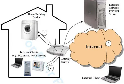
Figure I. Possible kinds of authentication in a home/building automation scenario
Case 1 refers to an authentication process while using internal home and building network system at home and building, an internal client (e.g. PC, micro, touch-panel) receives authentication from an internal server to control internal devices (e.g. washing-machine, controllers, actuators, lights, boiler). Case 2 refers to authentication process while using external home and building network services at home and building, an
internal client receives an authentication from a network provider server through an internal server to use services provided by the network provider server. Finally, case 3 refers to in an authentication process while using an internal home and building network system from outside, an external client receives an authentication from a network provider server to control internal devices. The thesis deals only with authentication process while using internal home and building network system inside home and building. The thesis has been organised as follow: the introduction (this chapter) gave an idea of what this thesis work is about, second chapter will give an overview on what is the state of art and what is the KNX standard, so it will focus on home and building networks based on KNX communication system.
At this moment, KNX standard does not foresee authentication mechanisms and data encryption and for this reason, in chapter 3, a proposal for an authentication process, based on data encryption and fully compliant with KNX standard will be presented [1], [2], [3].
As the spread of the internet connection has increased, recently a new part of the KNX Standard has been released that foresee the KNX – IP network integration; chapter 4 will be focused on congestion issues in KNX/IP standard that foreseen the integration of KNX networks with the IP networks.
Chapter 2
KNX Standard overview
Among many different standards available in home and building automation field, the KNX standard is the world’s only open standard for home and building automation [4]. Using the KNX standard give many advantages because it is application independent, application profiles have been integrated into the standard and every device compliant with the KNX standard must be certified. That implies that devices from different vendors can coexist if every one of them passed the KNX certification procedures.
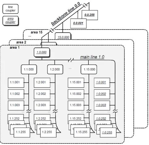
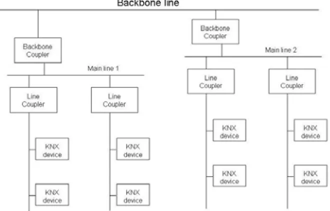
Communication medium is based on bus system. This allows for greater scalability and lower costs of management. Use of a single bus connecting all the devices in a home or a building is not possible. That is why the environment is logically divided in areas and lines. Every lines is
powered by it own power supply and connected to the others through line couplers as it can be seen in figure II
Figure II KNX network topology
.
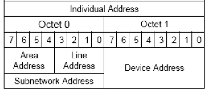
Every single device connected to the network is addressable by its address that is composed by the area identification address, line identification address and the device address.
Figure III. KNX address format
Devices connected to the network must be configured. Many configuration modes are available:
• System mode: Useful for expert installer. This configuration mode allows configuration even of complex functionalities.
• Easy mode: It represents an easier way to configure devices, but it allows configuring less complex functionalities.
• Automatic mode: It has been foreseen for the consumer allowing them to use a Plug&Play mode.
Configuration of the devices is possible due to a tool developed and distributed by the KNX standard organization. That tool is called ETS [5]. The ETS (Engineering Tool Software) has been realised by the KNX organization and every device that has passed the compliant process with the KNX standard can be configured through the ETS tool. The ETS software allows to create a configuration network, setting up all the necessary for device configuration. Once a configuration is ready it can
be deployed through bus on all devices connected to the network. The ETS software allows a point-to-point configuration mode with a device not connected to the network but directly connected to the device where the ETS tool is running.
Devices can send and receive data through many different transmission medium. In fact many transmission medium have been foreseen in the standard: twisted pair, power line, radio frequency. In particular, the power line and radio frequency transmission medium are useful if it cannot be possible to make radical change to building wiring as power line allows communication on an already present electrical wiring, while the radio frequency allows communication without use of additional wiring.
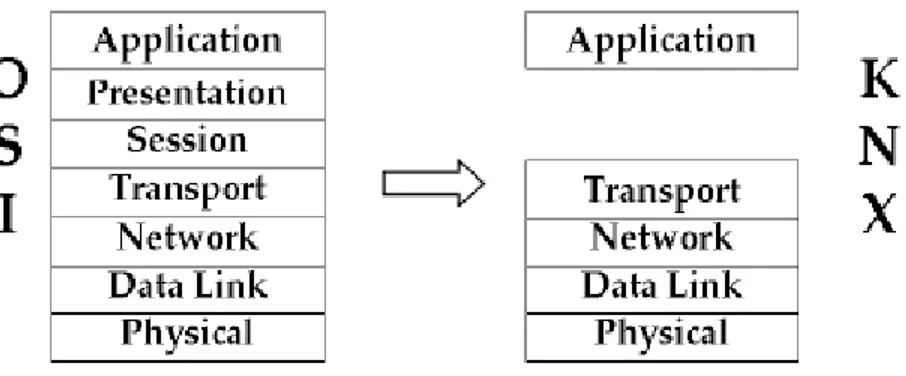
KNX standard protocol stack refers to the OSI (Open System Interconnection) model developed by the ISO (International Standard Organization). KNX protocol stack is based on a subset of the OSI layers. In fact, the KNX protocol stack foresees the presence of the application layer, the transport layer, the network layer, the data link layer and the physical layer.
Figure IV. KNX protocol stack
The application layer [6] allows the application processes to access datapoints. Datapoints are abstract objects that represent an internal object (called Application Interface Object). Data exchanging is possible thanks to the write and read services available in the KNX standard for writing and reading datapoints. This implies that application processes can cooperate exchanging information using the application layer services.
Transport layer [7] allows four kind of communication between devices. In particular it allows:
• multicast communication mode that consists of a transmission starting from a source device whose destination are a group of devices;
• broadcast communication mode that allows a sender to send a message to all devices connected to the bus;
• point-to-point connectionless that allows communication between two device without any channel establishment;
• point-to-point connection oriented that allows two devices to exchange information after a reliable channel establishment.
Network layer [8] deals with problem about telegram routing. In particular it manages all routing issues, which is telegram forwarding when source and destination devices belong to different sub networks, areas or lines.
Data Link Layer [9] includes the medium access control (based on the CSMA protocol defined in EN50065-1) and the logic link control. According to the medium access control, each device can start medium access procedure only if the bus has been free for a period of time value, chosen randomly and uniformly distributed between 85 msec and 115 msec. If within 35 ms from the end of the message transmission an ack has not been received, transmission is considered failed; in this case, the transmission can be tried again until a maximum of 2 times. If the bus is always busy or the number of maximum retry has been reached, the transmission is considered failed and this event is communicated to the upper layers.
Physical layer [10] manages all the issues about electrical transmission. It allows transmission of data stream without knowing anything about the meaning of the stream. It only deals with the electrical transmission of a single bit coding a single bit in a standard way.
Home and building automation is nowadays may involve a great choice of applications referring to a specific area, among which control, surveillance and entertainment. The data exchanged in some of these environments may be critical, because it may involve particular commands whose destination are particular actuators.
To protect critical data exchange between devices connected to the home and building automation networks a secure transmission inside communication systems is needed. Secure transmission generally included a security mechanisms to protect data exchanged and authentication mechanisms in order to guarantee to install and to give access only for trusted devices.
The first part of the thesis deals with security and authentication inside the KNX, which already met the requirements of both European Cenelec standards EN 50090 as well as EN 13321-1 and it has been recently approved as an international standard (ISO/IEC 14543-3), confirming its relevance in the home and building automation field [11][12][13].
At this moment, KNX standard does not support any security and authentication mechanisms. In literature, some proposals improving
secure transmission in KNX are present. Among them, one of the most remarkable is that presented in [14], called EIBsec. EIBsec foresees the presence of a complex device called ACU (Advanced Coupler Unit), which consists of a normal KNX coupler unit plus a key server unit. Cooperation among several ACUs, through ad-hoc services, realises security and authentication all over the network.
In this thesis, another security and authentication solution has been presented; it is fully compliant with KNX standard, as it realises security and authentication through exchanges of information based on already existing services at KNX application layer and on KNX application objects.
Chapter 3
KNXnet/IP Standard overview
Since June 2009, KNX standard specifications have been expanded with the KNXnet/IP system specifications [15]. These specifications (called KNXnet/IP specifications) define how the KNX protocol implementations have been integrated on top of Internet Protocol and how the KNX networks can be connected to an IP network, which is actually the most widely used network. So, KNX integration with the IP networks allows extending the building control communication capabilities, not limiting it to the local KNX control bus.
• One KNX segment (that is a communication bus chosen among one of the communication medium foreseen in KNX Standard specifications).
• A KNX-to-IP device (that is a router that provides network connection between a KNX network and an IP network).
A KNX-to-IP device (called KNXnet/IP Router) is connected both on the KNX side and IP side, so it has been configured (or it has obtained) one address for each network it is connected to. The addresses just mentioned are a KNX address on the KNX side and an IP address on the IP side of the router. That means that the router has two interfaces, one per side. On the KNX side (namely for the interface connected to the KNX network), the router has (or obtains) an individual address comply with the KNX standard address. The same concept can be applied to the IP side (i.e. the interface connected to the IP network) whose interface has (or obtains) an IP address comply with the IP protocol.
Due to the transmission speed, the IP network can be considered as a fast backbone if compared with the KNX networks speed. In this scenario the KNXnet/IP router can counter many problems in routing packets as it routes packets between a high speed network (IP) and a slow speed network (KNX).
The most critical routing condition will occur when the KNXnet/IP Router routes packets from the IP network to the KNX network, which is
from a high speed network to a slow speed network. In that case the KNX network represents a bottleneck in routing packets due to the low transmission speed compared with the IP network transmission speed. The KNXnet/IP system specifications define services for device management, routing, remote logging and remote configuration and diagnosis.
The device management section describes services and frames format for device remote configuration and management. The routing section describes the topology, telegrams, the router implementation rules and guidelines in general. The remote logging part of the specification describes the off-line monitoring capabilities of KNX networks. The last section shows how to control remote configuration and to perform remote diagnosis.
All KNXnet/IP structures involved follow a common rule: the first octet represents the length of the whole structure; this is necessary due to the variable length of each field depending on the data type (indeed it is possible to transmit different data type for example string, int, etc…) while the second octet is an identifier that specify the type of structure. The data structure starts from the third octet.
Regarding the frame structures every section of the standard defines frame structures depending on the available services described in their respective sections.
Communication between KNXnet/IP devices is based on a particular frame called KNXnet/IP frame.
A KNXnet/IP frame consists of a frame header and an optional body of variable length. The whole KNXnet/IP frame is coded binary using a big endian mode.
Every KNXnet/IP frame contains the KNXnet/IP header that contains information on the protocol version, the header length, the KNXnet/IP service identifier and the complete KNXnet/IP frame total length. Some other information (like timestamps) is not included in the header section of the frame as this information is related to KNXnet/IP service type so it will be included in the body.
The header length should be a constant but it could change if another protocol version is used. The only valid protocol version at this time is 1.0. The KNXnet/IP service identifier represents the action to perform and the payload data type contained in the KNXnet/IP body. The total length represents the length of the complete KNXnet/IP frame, including both the header and the body sections.
Different sections of the standard foreseen the presence of different available services that are described in the respective sections. Every section described in the standard defines different frame format according to the service involved, but the header structure, described above, remains the same for all service type.
The term “KNXnet/IP Routing“indicates a set of KNXnet/IP routers connected to an IP network. The routers perform packet routing between KNX networks and IP network that acts as a fast backbone. The KNXnet/IP router can replace the KNX Backbone Coupler or the KNX Line Coupler connecting the KNX networks to an already existing cabling (e.g. Ethernet).
Every device (including Line Coupler and backbone Coupler) has its own unique KNX Address that should be consistent with the topology according to the KNX standard addressing. Couplers telegrams’ filtering is based on this addressing consistency in point-to-point communication mode. A group telegram sent by a KNX device will be routed from coupler to coupler until it reaches the destination device or devices. An example of KNX network is shown in figure IV where a typical KNX topology is shown without the integration with the IP network.
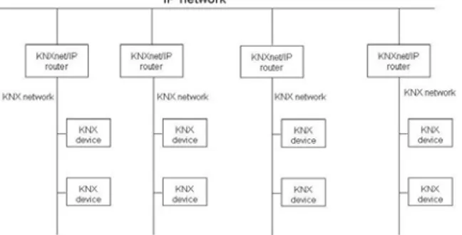
Figure V and VI show examples of KNX network integrated with IP network. In particular the figure V represents a scenario in which standard KNXnet/IP routers are connected directly to the KNX devices through the KNX bus. The KNXnet/IP Router provides Line Coupler functionality in addition to Router functionality.
Figure VI. An example of KNXnet/IP network
While, in figure VI a mixed environment is shown. KNXnet/IP Routers are connected to the KNX main line. Data exchange between KNX devices in different subnetworks is possible through Line Couplers and/or KNXnet/IP Routers.
Figure VII. An example of mixed KNXnet/IP network
A KNXnet/IP Router does not establish a communication channels between each other. A KNXnet/IP Router always transmit data to all KNXnet/IP Routers that belong to the same IP multicast address on the same network. It is possible to route data abroad the network or other network through normal standard IP routers.
Users and manufacturers expresses the desire to use the IP network as a native communication medium for KNX so a normal KNX device, that supports for example Twisted Pair (TP) as transmission medium, would have only one physical interface that is the interface connected directly to the IP network. Other communication medium is also possible, for example Power Line (PL) or Radio Frequency (RF) instead of Twisted Pair (TP) as mentioned in the KNX standard.
The KNXnet/IP Router should be able to manage all the theoretical maximum IP traffic, but fault conditions can occur, so it is possible to
have packets loss condition in particular for packets coming from the interface connected to the IP network whose destination is a KNX device located in the KNX subnetwork connected to the KNX interface side of the router. Many kinds of fault conditions can occur, an example is due to physical connection fault on the bus (e.g. cable disconnected) or traffic on the network that mean that traffic load is too high and the routers are not able to manage all traffic.
Every single fault condition is mapped with a particular ID that uniquely identifies the fault condition. The list of IDs is defined for each subsection and they are shown in the standard.
All KNXnet/IP Routers have a KNX Individual Address of type x.y.0 or x.0.0 where “x” stands for Area Address while “y” stands for Line Address, so all KNX telegrams, whose destination address is an Individual address, received by a KNXnet/IP Router must be processed and filtered as the router was a Line Coupler or an Area Coupler. That means the Router must forward the telegrams directly to the Area and respectively to the Line belong to the Individual Address of the KNXnet/IP Router.
All KNX Group address telegrams received by a KNXnet/IP Router must be processed and filtered on the basis of the Group Address, if the filtering functionality is on.
A KNXnet/IP Router shall provide two telegram queues. Both of them allow queuing at least two telegrams for the KNX side and at least two telegrams for the IP side. Any telegram cannot be instantly forwarded but it must be queued in the respective telegram queue if it is possible.
The KNXnet/IP Router may support two forwarding policy in case two or more telegram is waiting in the telegram queue. The first mode, called priority/FIFO, foreseen that the telegrams with the highest priority shall be routed first even if there are other queued telegrams with lower priority. The second mode, called normal FIFO, foreseen the transmission of the telegram that was queued first, regardless of the KNX priority. Priority/FIFO mode is not a compulsory functionality, so a KNXnet/IP Router must guarantee at least the FIFO mode functionality. The KNXnet/IP Router discards all telegrams in the queue if bus connection failure has been detected. Telegrams loss is even possible in case of queue overflow; in that case the KNXnet/IP Router will discard the last telegram received that was not possible to queue. Every time the KNXnet/IP Router receives a telegram it evaluates the Routing Counter field of the frame just received. If it is not zero and not seven, it will be decremented by the KNXnet/IP Router before to be routed. If the Routing Counter is zero the telegram received from the KNX network or IP network will not be routed anymore. If the Routing Counter is seven
the telegram received from the KNX network or IP network will be routed without decrementing the Routing Counter.
KNXnet/IP Routers should provide routing functionalities as factory settings and without the user intervention, so default configuration consists of the following rules, as described in the standard: first of all routers default Individual Address must be FF00h as factory setting. KNXnet/IP Routers should be able to route all KNX broadcast telegrams from one KNX subnetwork to another subnetwork even if factory default configuration is still active. In that case KNXnet/IP Router acts transparently as normal KNX router (that are Line and Backbone Couplers).
KNXnet/IP Router shall work even if it has not obtained a valid IP address on the IP side and in particular, if a KNX Individual Address has been assigned on the KNX side, the KNXnet/IP Tunnelling service shall be available for configuration.
All KNXnet/IP Routers must be able to process every telegram received from the KNX subnetwork applying what has been said before, which is every telegram received by KNXnet/IP Router is subject to filtering. Different policy filtering can be applied depending on the KNX telegrams received. In fact, the Router will apply different filtering depending on whether the telegram received is a group address telegram or individual address telegram, as described above.
On the IP side, the KNXnet/IP Router receives UDP/IP datagram that target its own routing multicast IP address. The filtering of IP datagram is based mainly on port number but also on multicast IP address and filter table.
In addition, the routing counter must be taken into account both for telegrams received on the KNX side and for IP side.
On account of what said before, the first filtering operation to which telegrams from IP side are subject is based on port number. Indeed all KNXnet/IP Routing datagram shall target UDP/IP port number 3671. Datagram received on ports that do not match port number 3671 will be discarded, so only datagram received on port number 3671 will be processed for routing to the KNX subnetwork. The port number 3671 is a registered port number at the Internet Authority for Number Assignment (IANA).
From the security point of view, the standard says that KNXnet/IP Routing frames are not encrypted, that means that the frames will not be subject to any overhead or delay in addition of that provided for the transmission on the bus and device internal computation delay. Obviously this implies no security level during transmission on the network.
The transmission in clear does not represents a limitation for remote controlling of the building because even though frame transmission is in
clear it will occur limited to the internal building network. Indeed it is possible to send and receive KNXnet/IP Routing frames over external building networks thanks to Virtual Private Networks (VPN) because they will be encrypted due to VPN protocol, transparently for the KNXnet/IP Routers.
The KNXnet/IP protocol was developed by the KNX Task Force IP. Some of the KNX Task Force IP main objectives were:
• maintain the simplicity and scalability of the KNX system
• allows reusing existing stack implementations as much as possible
• add capabilities of the KNX systems for advanced applications KNX does not require knowing who the sender of a KNX packet is to know who will receive that packet. In particular the KNX group addressing allows the sender to send a packet to an unknown number of devices. That implies that the sender configuration will not be modified if devices will be dynamically connected to or disconnected from the network. Equally there is no limit for the number of senders that send packets to the same group address and there are no changes to be made to the receiver’s configuration.
This scalability and simplicity have been transferred even in KNX networks integrated with IP network.
The IP addressing method allows using two communication modes: unicast and multicast. If unicast communication mode was used every KNXnet/IP Router would have been configured to send data to a pre-defined list of devices. Even in case of dynamic changes on the network (i.e. device connected later than network first start up) the KNXnet/IP Router needs to be reconfigured. That requires more resources in every single devices and it implies more traffic on the network. In fact, sending packets using unicast addressing mode increases the number of packets that the sender has to send by a factor depending on the destination devices.
Unicast communications may be confirmed by sending back an ack message so the number of packets involved for a single transmission from a sender to a receiver further increase.
That means that if a sender wants to send a packet to N devices it sends the same packet N times, one per devices. In addition, all devices confirm the transmission sending back to the sender an ack message, so it is clear how the traffic on the network increases. That is an issue for scalability. That is why unicast communication mode is used only for KNXnet/IP Tunnelling and KNXnet/IP Device Management protocols where a direct connection (and confirmation) is needed between device and configurator.
The other IP addressing method is multicast. It allows maintaining behaviour similar to KNX. Indeed, a multicast packet is sent once by the sender and it can be received by one or many target devices at the same time. It is clear how multicast allows maintaining scalability and simplicity at the same level of KNX system and this is why KNX Task Force IP has chosen the multicast addressing mode for KNXnet/IP Routing protocol.
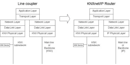
Following the directives above mentioned (allows reusing existing stack implementations as much as possible) it is also possible to carry minimal changes to the existing stack implementations. Changes do not involve upper layer because they are “independent” from the physical layer. What has been changed is the physical layer. That was necessary as the physical layer manages the connection and all the electrical signals in order to adapt them to the communication medium and allowing transmission on the bus.
The following figure (figure VII) shows the changes applied to the Line Coupler during the evolution process to KNXnet/IP Router.
Figure VIII. Line Coupler to KNXnet/IP Router evolution
As the standard says the Line Coupler can be configured via bus through KNX standard services, while the KNXnet/IP Router can be configured using the KNXnet/IP Device Management services in addition to the classic configuration via bus used for KNX devices.
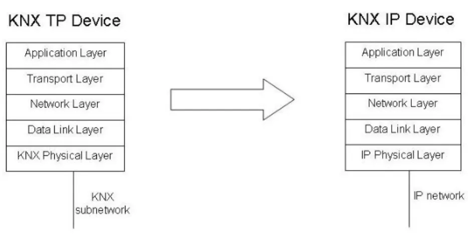
As mentioned before, users and manufacturers express the desire of having a native KNX IP device, that means a KNX device with only one interface connected to the IP network.
Even in this case the KNX communication stack needs to be modified. In particular the KNX physical layer must be replaced by the IP Physical Layer. So figure VIII shows the KNX device to KNX IP Device stack implementation evolution.
Figure IX. KNX Device to KNX IP Device evolution
The existing stack implementation and management procedures are retained, the change regards the communication medium and then the Physical Layer. Also in this case configuration process can be achieved via bus (using KNX services). In this case configuration is done sending the KNXnet/IP Routing packets using KNXnet/IP Services.
Another way to configure devices is through KNXnet/IP Device Management services. The KNXnet/IP Device Management services are used for configuration, but the original KNX Device Transport Layer is not sufficient to support KNXnet/IP Device Management services so the Transport Layer has been enhanced. The improved Transport Layer is called cEMI Transport Layer (common External Message Interface). The cEMI Transport layer does not replace the original KNX Transport
Layer. The cEMI Transport Layer will be used only when necessary (i.e. for configuration).
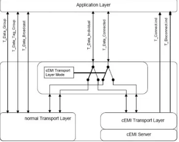
The figure IX shows the scheme for a KNX IP Device with the cEMI Transport Layer and the normal Transport layer. The use of one of the available Transport Layer is dependent on the connection established for KNXnet/IP Device Management. The cEMI Transport Layer is activated until a KNXnet/IP Device Management connection is established.
Figure X. Schematic of a KNX IP Device with normal and cEMI Transport Layer
Summarising, a KNX IP Device needs a new Physical Layer in order to be connected directly to the IP medium so in every single device IP Physical Layer replaces KNX Physical Layer.
The configuration of a KNX IP Device can be achieved via bus using KNX services and normal Transport Layer version using the KNXnet/IP Routing services.
The other configuration option is to enhance the original Transport Layer adding configuration capabilities in order to create the so called cEMI Transport Layer. If the cEMI Transport Layer is available and selectable by the “cEMI Transport Layer Mode” parameter, it is possible to configure device through the KNXnet/IP Device Management services. Configuration via KNXnet/IP Device Management services (using the cEMI Transport Layer) is better if compared with configuration via KNXnet/IP Routing and the normal Transport Layer because the KNXnet/IP Device Management services establish point-to-point connections with the device. In addition, KNXnet/IP Device Management services have ten seconds time out while the KNXnet/IP Routing services (using the normal Transport Layer) have three seconds time out. It is clear that KNXnet/IP Device Management services are suitable even for long-distance devices configuration if compared to KNXnet/IP Routing services.
Chapter 4
Security in KNX
4.1 Overview
At the moment the KNX standard does not provide any security mechanisms. It is possible to define 255 security level but they are useful only during configuration. During data exchange no encryption or authentication mechanisms have been defined bye the KNX standard, so every data exchange involves sending data in clear on bus.
In particular KNX does not support any key management, generation or distribution procedures.
To protect data from unauthorized reading it is possible to perform some operation on the data in order to get them unreadable to third parties or to unauthorized entities. That means applying cryptography to the data
before being sent and decrypting when received. So data on the bus will be sent encrypted and only the two partners can decrypt them.
Cryptography is the science of writing in secret code. Modern cryptography techniques can be divided in Symmetric and Asymmetric cryptography. In symmetric-key cryptography both the sender and receiver share the same secret called “key”, used for encryption and decryption of each information exchanged between them. One of the most popular and secure algorithms used in symmetric cryptography is AES (Advanced Encryption Standard)[16]. AES is a fast algorithm both in hardware and software implementation and can be implemented even into a limited-resource microcontroller. The main disadvantage of symmetric ciphers is relevant to the key management, because each pair of communication devices must share a different key, so for example if the network has N devices, each device needs (N-1) keys to communicate and to exchange data with the other N-1 devices. Furthermore, using symmetric cryptography it is difficult to establish a secret key between two devices through an insecure channel.
In 1976, Whitfield Diffie and Martin Hellman proposed the concept of public-key cryptography also known as asymmetric cryptography [17]. In asymmetric cryptography two different keys are used. The keys are not equal but they are mathematically related; they are called public key and private key. Public key is known to everyone that wants to encrypt any
message to be sent; it is computationally infeasible calculate private key knowing only the public key. The public key can be distributed to everybody but the private key must remain secret. The public key is used to encrypt messages and only the private key can decrypt them, that’s why the private key must remain secret. Diffie and Hellman proposed a key-exchange protocol to allow devices to exchange the keys through an insecure channel. The Diffie-Hellman protocol uses the “Multiplicative group of integers modulo p”.
The following example tries to explain the Diffie-Hellman algorithm and involves a “device” (i.e. a communication node) that wants to access the communication and a particular device, called “controller”, which is in charge to create the secure transmission. The controller chooses three numbers called “g”, “p” and “a”; for example it chooses g = 4, p = 11 and a = 3. Number “a” must be kept secret. The controller sends to the device “g”, “p” and “A = (ga) mod p” (so it sends g = 4, p = 11 and A = 9). The device receiving the data set “g”, “p” and “A”, chooses its secret parameter “b” (for example b = 7) and sends back to the controller the number B = (gb) mod p (so it sends back B = 5, in the example). The device computes its temporary key, K, equal to (Ab) mod p; at the same time, the controller computes its temporary key given by (Ba) mod p. Both the controller and the device now have the same temporary key because Ab = Ba , in fact A = ga and B = gb so Ab = (ga)b = (gb)a.
The key for this example is K = 4. As already seen, the only secret parameters are “a”, “b”, ga·b, gb·a. Of course, much larger values of “a”, “b” and “p” are needed to make this example secure. Many studies showed that it is computationally infeasible calculate “a” given only “g”, “p” and ga mod p (these parameters are sent in clear through the network). This problem is known as “the discrete logarithm problem”. Although cryptography protects data from unauthorized viewers, an authentication mechanism is needed in order to understand if a device is a trusted device (a KNX device that supports encryption), or a malicious device whose job is to send data on the bus as it was an authorized device or just to perform a deny of service attack.
In computer science the challenge authentication algorithms foresee that a device challenges another device that will be authenticated only if the response to the challenge is correct [18].
Among the authentication schemes currently available (see [18][19][20] for an overview), that based on challenge algorithms has been considered in the proposal; it foresees that a device challenges another device that will be authenticated if and only if the response to the challenge is correct [18].
On the basis of what said, the request of user’s authentication information made by SS to a SC is realised by a challenge; the
authentication process succeeds if the SC gives a correct answer to this challenge.
Challenge-based approach will be used in the proposal presented in the thesis in order to allow the device to be included in the list of trusted devices.
4.2 System model
The main guideline in the definition of a security mechanism is that it must be used in a standard network without imposing any modification to current protocol and must permit the consistence with not-secured devices. Furthermore, it must cover the following phases:
• authentication of new devices during the installation
• realisation of both consistency and privacy of exchanged information.
The agents involved in our proposal are:
• the Secure Client Device (SC) SC is a generic device whose transmission must be secured.
• the Secure Server Device (SS) that is the core of our proposal; it is a device dedicated to manage security and to store security tokens.
• the Installer (ID) is any device (e.g. laptop, PDA) which is equipped with hardware and software tools needed to communicate with standard devices plus security framework. After an authentication step useful to authenticate the device that wants to be connected to the network, the device will be given a network key. Secure exchange of data by a SC is realized through a shared secret (that is the network key) between all SC. That means they share a common (secured) channel;
That approach offers the following advantages:
• exchange of information is the same of plain (unsecured) home network;
• no significant overhead in the number of messages; • full compatibility with standard devices.
Secure exchange of data by a SC is based on a common secret shared by all SC; That approach offers the following advantages:
• exchange of information is the same of plain (unsecured) home network;
• no significant overhead in the number of messages; • full compatibility with standard devices.
Mechanism to share a channel is based on the classical mechanism of a shared key between devices, called in the following Network Key (KNET).
• SCA → SCB : E(KNET,DATA) • SCB → SCA : E(KNET,DATA)
The network key (called KNET) must be given to trusted (or authenticated) device only. The easiest way to authenticate a device is to embed something like a secure device (e.g. like chips into smart cards) able to manage and store private keys. Although this approach represents the best security solution it can’t be easily applied to already installed systems.
Alternative approach is the use of DH algorithm to exchange KNET, as follows:
1. ID → SS: DH(KID,PUB) 2. SS → ID : DH(KSS,PUB)
3. ID,SS calculate K=f((KID,PUB),KSS,PUB)) 4. SS → ID : HASH(KINS, K, UniqueId(SS)) 5. ID → SS : HASH(K, KINS, UniqueId(SS)) 6. ID → SS : E(K, KTMP)
Where UniqueId is the value associated to all KNK devices, or any other token that could be present, and HASH(x, y, z) is a hashing function whose result depends on a combination of the parameters x, y and z.
Steps (4) and (5) are used to verify that both agents share the same information in order to authenticate the Secure Server to the Installer and vice versa. This procedure is adopted also by the ID to provide KTMP to SC, than this key is used to distribute the network key.
The mechanism discussed above use the pre-shared key (KINS) known by both the SS and the ID to avoid MITM attack. In addition the KINS must be download to the SC before being connected to the network (i.e. out of the band).
The protocol implementation is based on KNX point-to-point connectionless application layer services A_PropertyValue_Write and A_PropertyValue_Read. [6]
The data structures, needed to support the security mechanisms, has been made using existing KNX datapoints at the KNX application layer [6]. The following KNX Application datapoints have been defined to manage Diffie-Hellman:
• Diffie-Hellman α, q, Y (DHαqY): this is the container for the receiving α, q and Y parameters, sent by the Installer.
• Challenge Object (CO): this is the container of the challenge code sent by the Installer.
• Network Key (KNET): this object contains the Network Key sent by the SS.
• Secured Node List (SNL): this is an address list of the authenticated SC.
The application objects defined for the SS are:
• Diffie-Hellman α, q, Y (DHαqY): it’s the same datapoint defined for the SC. Also in this case, it’s written by the Installer.
• Challenge Response (CR): this object will contain the response sent by the Installer to a previous challenge made by the SS. As said before, all the previous datapoints are read and written using the A_PropertyValue_Read and A_PropertyValue_Write services, respectively.
The implementation of the proposal is featured by particular management procedures needed to achieve its best performance.
Some of these procedures deal with the management of the Secure Node List (SNL) by SS; each time the SS will succeed to send the Network Key to a SC, its address is added to the SNL, and SNL is forwarded to all the SCs already authenticated. Update of this list into each SC is realised by the SS using the A_PropertyValue_Write onto the SNL object maintained by each SC.
In order to improve the security, the Network Key could be periodically changed by SS. For this reason suitable mechanisms have been foreseen in order to allow the SS to generate and send another Network Key to all the SCs included in the SNL using the already secured channel.
A particular effort has been put in the validation of the proposal using a formal verification approach. It aims at verifying the correctness of the state machine describing the basic protocol above discussed.
Verification and validation means, among others, to perform a reachability analysis and checks for deadlocks. The validation has been carried on by simulating the Estelle model [21].
Estelle modelling is possible thanks to the Estelle Development Toolset (EDT) [22] that is a software able to test a system implementation starting from its Finite State Machine (FSM).
Estelle represents a formal description technique useful to describe and test communication protocols. Estelle is described in details in [21]. An Estelle model is based on hierarchical Finite State Machine that can evolve simultaneously and can exchange data through message exchange and/or shared variables.
The most important components included in the Estelle Development Toolset (EDT) [22] are:
• an Estelle compiler: it checks for errors in the model. If there are not any errors translate from the Estelle formal description to C language,
• an Estelle Simulator and Debugger: it checks for run time errors; • an Estelle Browser: it allows the user to generate a
• an Estelle Graphical Editor: it allows the user to describe the system specification through simple graphical steps;
• an Estelle Table and Events Generator: it creates all tables containing states and events for each finite state machine. Every table describe the corresponding module behaviour;
A system described in Estelle foreseen the presence of various components. Every component is described by a “module definition”. It can be possible to have multiple instances of a “module definition”. To describe a module implies a complete action set description (called system state transitions). A module can include one or more sub modules that are able to exchange messages. A module is defined as “active” if it has at least one transition definition.
Communication between modules is possible through their communication access points called “interaction points”.
Each interaction point is assigned two sets of interactions. An interaction is a message exchange with other modules, so an interaction is defined for incoming messages coming from some other modules and an interaction is defined for outcoming messages sent to another module. Modules can send messages (interactions) to other modules through a communication link.
Every time an interaction is received by a module it will be queued in a queue where the first interaction received will be the first to be processed
(First In First Out queue). It is possible to choose if each interaction point has it own queue or if only a queue is shared between two or more interaction points.
Another way to exchange data is possible and consists in sharing variables. A shared variable is a variable owned by a module that can be accessible by other modules. A concurrent variable access is based on the parent / children priority. It means that the parent module has always higher priority than the children modules.
Simulation of the model allowed us to verify the formal correctness of the encrypting and authentication procedures.
4.3 Results
A study has been done in order to verify the feasibility of the implementation of the proposed security solution using the hardware/software resources generally required by a KNX device. The feasibility study considered the two implementation issues which could introduce criticisms in the realisation of the proposed approach: ROM utilisation to store the code relevant to the entire authentication process and execution times of the data encryption and authentication procedures. The analysis has been carried on considering the Texas Instruments MSP430 family, as it’s one of the most used controllers to implement KNX device, as explained in several papers presented in literature (see
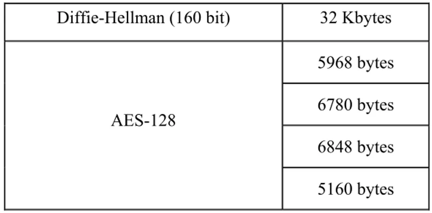
for example [23]). Results of the analysis about the space needed to store the code implementing the authentication process will be presented in the following, for both the SC and SS; as the proposal is mainly based on Diffie-Hellman[17], DEK hashing [24] and AES algorithms [16] the analysis has been limited to these algorithms.Diffie-Hellman algorithm and related code depends on the role played by the device, i.e. Security Client and Security Server. Literature presents an evaluation of the ROM utilisation needed to store the code of the Diffie-Hellman algorithm, considering a key length of 160 bits; the reader may find more information about this analysis in [25]. The same has been done for the DEK hashing algorithm; it has been implemented by the author on a MSP430 family and the relevant ROM utilisation has been evaluated. About AES, implementation hasn’t been considered necessary, as literature offers many examples of AES implementation and optimisation on microcontrollers. In [22], [23], [24], [25], [26], [27], [28] ROM utilisations of AES-128 (i.e. AES using a 128 bit key length) adopting MSP430 family can been found. Table I summarises the ROM utilisation due to store the hashing, the Diffie-Hellman and the AES-128 codes.
Algorithm ROM/Flash Usage
Diffie-Hellman (160 bit) 32 Kbytes 5968 bytes 6780 bytes 6848 bytes AES-128 5160 bytes
Table I. Total code ROM utilisation
As can be seen the Table I shows the ROM utilisation of the Diffie-Hellman codes considering a 160 key length implemented in [25]. About AES-128 algorithm, the Table I reports that the ROM utilisations of implementations available in literature range from 5160 bytes to 6848 bytes. Considering the best implementation of AES (5160 bytes presented in [28]), the implementations of Diffie-Hellman (32 Kbytes) and hashing algorithms (4 Kbytes), we achieve a total ROM utilisation of about 41 Kbytes to implement the three algorithms considered. Recalling that MSP430 allows up to 92 Kbytes of ROM and that a complete KNX stack protocol implementation requires about 20 Kbytes of flash memory [23], it is possible to state that inclusion of code relevant to Diffie-Hellman, hashing and AES algorithms inside a KNX device is possible without exceeding the total capacity of the flash memory for the microcontroller family considered. In conclusion, the analysis carried on
about the extra space required by the proposed approach, allowed to state its feasibility in terms of hardware resources. The execution time could be a critical issue for a simple device like that involved in a KNX system, so time analysis for the execution time of the encryption and authentication procedures has been done; again this analysis has been limited to the Diffie-Hellman, DEK hashing and AES algorithms. Evaluation of the execution time for the hashing algorithm has been done using the code developed by the authors; the implementation has been based on MSP430 family and assuming a frequency of 8 MHz. Evaluation of the execution time for the Diffie-Hellman algorithm has been derived from the results presented in [25], which again assumes an implementation based on MSP430 family and a CPU frequency of 8 MHz.
Concerning the AES algorithm, [16] presents the values of the encryption times of the AES-128 implementation proposed in [18], [19], [20], [21], considering again the MSP430 family and a frequency of 8 MHz. Table II summarises all these times.
Algorithm Execution Times
DEK Hashing algorithm 0.065 msec
Diffie-Hellman (160 bit) 1.04 sec
Table II. Execution time for the algorithms
In order to better asses the execution times of the Diffie-Hellman, hashing and AES-128 algorithms, a comparison with those required by some basic operations performed by a KNX device has been considered necessary. The basic operation considered in this analysis regards communication and is the transmission of a datagram in a KNX communication system. As known, the transmission speeds for the different media supported by KNX standard are 1200 bits/sec (PL110) [29], 9600 bits/sec (TP1) [30] and 16384 kbits/sec (radio frequency) [31]. Lengths of the supported frames in KNX range from 184 to 2104 bits. So the transmission times range between the values given by Table III, achieved considering the highest speed (16.384 kbps) and the shortest frame (184 bits), versus the slowest speed (1200 bps) and the longest frame (2104 bits).
Speed/Bits Transmission Time
16.384 kbps/184 bits 11 ms 1200 bps/2104 bits 1.75 s
Table III. Transmission times in KNX
Taking into account the values shown in Tables II and III, and considering the best implementation of AES-128 proposed in [28], it’s clear that the execution time for the hashing and AES-128 algorithms is negligible. About the Diffie-Hellman algorithm, Table II points out that
the Diffie-Hellman involves not trivial computing operations due to the asymmetric nature of the algorithm, although the execution time is less than the slowest transmission.
Analysis of Diffie-Hellman algorithm must be completed by the following considerations. According to the authentication process here presented, the Diffie-Hellman algorithm is executed only during the first step of the proposal until each SC achieves the Network Key; in this case, the not negligible overhead introduced by Diffie-Hellman algorithm leads only to a delay in the start-up of the entire secure communication. As already said, the procedure relevant to the distribution of the Network Key may be repeated; in this case, the Network Key should be changed after a period lower than the shortest period between those needed to break cryptographic key generated by Diffie-Hellman and AES algorithms, respectively. In order to have some idea on a realistic frequency at which the Network Key must be changed, in the following an example will be given.
Table IV shows the MIPS year needed to break keys generated by Diffie-Hellman (based on a 160 bit key) and AES-128 (based on a 128 bit key), respectively.
Algorithm MIPS year
Diffie-Hellman (160 bit) 1012
AES-128 1025
Table IV. Time need to break the key
According to the Table IV, it’s clear the Diffie-Hellman algorithm seems to be more sensible to an attack, requiring less computing resources; for this reason, frequency at which the Network Key must be changed must take into account only the effort required to attack to Diffie-Hellman algorithm. Table V shows the order of magnitude of MIPS featured by some computer architectures today available, ranging from common personal computer to supercomputer (see [32][33] to have a list of current computing platforms).
Architecture MIPS
(order of magnitude)
Actual personal computer architecture 103-104 Actual supercomputer architecture 108-109
Table V. Actual architecture processing order of magnitude
On the basis of the values presented by Tables IV and V, it’s possible to make some exercises in order to understand how long the proposed approach may counter an attack. Considering a realistic scenarios
featured by the availability of lower numbers of computing resources, it’s possible to state that cryptographic keys generated according the proposal, are able to guarantee many years of security.
On the basis of what said, it’s clear that although Diffie-Hellman algorithm introduces not trivial delays, its overhead on the system is limited due to the very low frequency at which the entire authentication process must be repeated; in fact, a block of the system for few seconds each many years doesn’t seem an excessive overhead for the system. In conclusion a way to introduce data encryption and authentication mechanisms into the current version of the home and building automation KNX standard has been presented. The proposal is fully compliant with this communication system as it uses some services available at the application layer and the relevant communication objects, in order to realise all the exchange of information aimed to secure the communication. The thesis has deeply presented the proposal pointing out compliance with KNX standard and presenting the main results about its validation through Estelle formalism.
The main differences with similar solutions present in the current literature have been pointed out. Finally results of a performance evaluation carried on in terms of ROM space required and execution times have been presented. The analysis pointed out that implementation
of the proposed solution seems feasible using common hardware resources currently used for KNX devices.
Furthermore, the overhead introduced by the authentication procedures in terms of execution time is generally negligible; only Diffie-Hellman algorithm introduces delays, but its impact on the overall performance of the system seems very low due to the very low frequency at which the Diffie-Hellman algorithm need to be re-executed.
Chapter 5
Congestion analysis in KNXnet/IP
5.1 Overview
As mentioned in chapter 3, KNX IP data exchange communications are based on KNXnet/IP Routing protocol. That implies some possible packets loss conditions.
• Routing from KNX subnetwork to KNXnet/IP Routing Multicast Address.
A KNXnet/IP router forwards packet from the KNX subnetwork connected to its KNX network interface to the IP network that is connected to the IP network interface of the KNXnet/IP Router. The KNXnet/IP Router routes packets to the other KNXnet/IP Routers using the KNXnet/IP Routing Multicast Address. If particular
network load conditions do not occur forwarding KNX packets from KNX network to IP network would not be an issue because the IP network transmission speed is three - four orders of magnitude higher than KNX network transmission speed. Due to the capabilities of the KNX subnetwork is not possible to have a scenario that foreseen more than 50 packets per second to be forwarded from a KNX subnetwork to IP network.
• Transmission across the IP network.
KNXnet/IP Routing protocol is based on IP multicast addressing. If certain network conditions occur some IP packets may be lost or dropped by devices in the network. Network device packets dropping occur if, for example an IP router discards packets due to congestion or particular traffic load condition in an IP network segment it is connected to.
IP packet loss cannot be detected by the sender because, as explained before, the transmission is based on KNXnet/IP Routing protocol that does not foreseen acknowledged communication.
The KNXnet/IP Routing protocol does not affect the performance of the network components (IP routes or switches) because IP routers or switches forward IP packets that incorporate KNX messages, that means that every single IP routers or switches do not process and do
not have visibility of KNX messages that are transparent to every IP network device.
If an acknowledged transmission is needed it is possible to use the KNXnet/IP Tunnelling services. Using the KNXnet/IP Tunnelling services avoids packets loss because of network, but at this time only KNXnet/IP Routes support KNXnet/IP Tunnelling services by default and it is not a mandatory requirements for KNX IP device but it is possible for a manufacturer to implement KNXnet/IP Tunnelling services in all KNX IP devices.
• Reception from the IP network.
Normally a KNX IP device hardware design foreseen the presence of an Ethernet interface to be connected to IP network and a microprocessor that allows some kind of computation or frame processing. In addition to these requirements a KNXnet/IP Router must be equipped with a KNX subnetwork interface (like TPUART) that allows the KNXnet/IP Router. If the Ethernet interface has not been designed to support the network data rate it is connected to, it is manufacturer’s design responsibility because whatever protocol would not be able to circumvent this issue.
• Interface inside KNXnet/IP router or KNX IP device that allows Ethernet interface and micro processor communication.
When a KNX IP device receives packets from IP network all packets must forwarded to the microprocessor in order to be processed. Depending on the hardware and software design the transmission rate between the Ethernet interface and the microprocessor could be lower than the packet receiving rate from the IP network. This implies that the packets received from the IP side and firstly processed by the Ethernet interface could be queued in the Ethernet chip queue before being forwarded to the microprocessor. This lead to packet loss condition if the actual packets queued increases more than the queue capacity. In general this is an unsolvable problem that could be caused by the following reasons (or a combination of them): wrong hardware design, wrong firmware and/or operating system and/or application software implementation. A simple solution can be to temporary stop the communication in order to allow the congested device to drain all packets in queue. After the congestion conditions end it is possible to restore the normal transmission rate between the sender and the received device. It is a simple solution but it does not guarantee that the problem can be solved because, first of all, not all Ethernet network device chips support this features, and it is not proven that it is an efficient solution.
KNX devices unsuitableness can not be removed whatever protocol is used for transmission. The only thing is to reduce the performance of
the whole system but it is against the main idea of the KNX – IP integration that is to improve KNX systems performance.
Device manufacturing is a manufacturer’s responsibility, so growth of system performance depends on the performance of single device. So the whole system performance depends on the product improvements that every single manufacturer applies to the device design.
To not force manufacturers to design high performance device only, a solution of classes definition is possible. Basing on the performance class definition every single device has a quality classes that identify its capabilities respect to receiving and processing packets.
Although different device classes exists a minimum system level for device performance has been defined, in fact every single IP device (both KNX IP device and KNXnet/IP Router) must able to receive and process a minimum number of packets (ROUTING_INDICATION) per second.
In theory, every single IP device (both KNX IP device and KNXnet/IP Router) should be able to receive and process at least 12750 ROUTING_INDICATION packets (remembering that a single IP packet is 64 octets). That number has been calculated in order to allow KNX IP device and KNXnet/IP Router to receive and process packets sent by 255 KNX IP devices or KNXnet/IP Routers whose