Lecture 3 : Mechanical
(forced) ventilation
IEE/09/631/SI2.558225 28.10.2011
Educational Package Ventilation
Supply-Only ventilation system (SOV)
Extract-Only ventilation system
A- Mechanical extract ventilation (MEV)
B-Intermittent extract fans and background ventilators
Balanced ventilation system
A-Single room heat recovery ventilators (SRHRVs)
B-Whole house mechanical ventilation with heat recovery (MVHR)
Fans and Blowers
Basic Acoustic Terminology
Noise sources
Design criteria
Air filters
Summary
Natural Supply-Only Balanced Extract-Only Natural exhaust Natural supply Mechanical supply Mechanical exhaust
Supply-Only ventilation system
4 basic types of ventilation systems
No.
in fig Type of air Definition
1 outdoor air air taken into the air handling system or opening from outdoors before any air treatment
2 supply air airflow entering the treated room, or air entering the system after any treatment 3 indoor air air in the treated room or zone 4 transferred
air indoor air which passes from the treated room to another treated room usually adjacent rooms
5 extract air the airflow leaving the treated room 6 recirculation
air extract air that is returned to the air treatment system 7 exhaust air airflow discharged to the atmosphere. 8 secondary
air airflow taken from a room and returned to the same room after any treatment (example: fancoil unit)
9 leakage unintended airflow through leakage paths in the system
10 infiltration leakage of air into the building through leakage paths in the elements of structure separating it from the outdoor air 11 exfiltration leakage of air out of the building through
leakage paths in the elements of structure separating it from the outdoor air 12 mixed air air which contains two or more streams of
air
Source: VENT Dis.Course, Distant learning vocational training material for the promotion of best practice ventilation energy performance in buildings
Module 3: Energy Efficient Mechanical Ventilation Various air flows in a mechanical ventilation system (EN 13779). 4 `
Particularities:
`
PIV consists of a fan to
supply air to spaces and
ventilation openings in
building envelope to
allow air to flow out of
the building;
`
Filtration of the
incoming air;
`
Can be used in a
polluted and noisy
environment
`
Adequate when the
occupants are
sensible of exterior
contaminates
SOV or
Positive input ventilation (PIV)
Source: Guide pratique “La ventilation méchanique des habitation”
Supply-Only ventilation system
house apartment building
office building
Fig.1
Description
A fan, typically mounted in the roof space, supplies air into the dwelling via central hallway or landing.
This creates a slight positive pressure in the dwelling
Control
The systems deliver a continuous flow of air to the dwelling;
Fan speed can be increased by occupant, or automatic switching;
5
Source: Energy efficient ventilation in dwellings – a guide for specifiers (2006 edition)
Supply-Only ventilation system
Installation
If the fan draws air directly from the roof space,
it will depressurize the roof space relative to the rest of the house upstairs ceiling has to be airtight;
the roof space needs to be adequately ventilated from outside
Maintenance
occasional cleaning is necessary;
intake filters (fitted to most units) will need occasional cleaning/replacement.
Fig.2
Applications
New build: good practice – depending on the individual system’s compliance with building regulations
New build: best practice ✗ Major refurbishment ✓ Minor refurbishment ✓
Advantages
A significant advantage of SIV in homes is that it creates positive indoor pressure, which helps prevent outdoor pollutants (e.g., radon) from entering;
Easy to install;
Operation is easy to understand; Heat gain to loft space is utilized.
Disadvantages
Limited research into their use
Some additional enhancement measures may be needed, dependent on building shape and layout
Methods
Continuous supply Single-point Supply Multi-point supply
Intermittent supply with inlet in return side of HVAC System
6
Supply-Only ventilation system
Source: Energy efficient ventilation in dwellings – a guide for specifiers (2006 edition)Source: Marion Russell, Max Sherman and Armin Rudd, Review of Residential Ventilation Technologies , Ernest Orlando Lawrence Berkeley National Laboratory, 2005
Example of supply ventilation integrated into the return side of an existing HVAC system (Building Science
Corporation)
Fig.3
A - Mechanical extract ventilation (MEV)
Extract-Only ventilation
system
Source: Energy efficient ventilation in dwellings – a guide for specifiers (2006 edition)
Source: Dr. Sam C. M. Hui, Department of Mechanical Engineering, The University of Hong Kong, lecture “Mechanical and Natural Ventilation”, 2011
(MEV) continually extracts air single-point exhaust systems multi-point exhaust systems
Advantages
easy to install;
provides continuous ‘low-level’ background ventilation;
small negative pressure in
building prevents moisture
mitigation into the constructions of external walls and prevents condensation and consequently
the mould growth;
Disadvantages
requires ducting from wet rooms;
air infiltration through the building envelope creates easily draught in winter in cold climate;
heat recovery from the exhaust air is not easy to implement; as the exhaust is usually from kitchens, bathrooms, and toilets ventilation supply air flow is not evenly distributed in the bed rooms and living rooms.
Fig.4
A - Mechanical extract ventilation (MEV)
Extract-Only ventilation
system
SINGLE-POINT EXHAUST SYSTEMS
Example of a single-point local exhaust system with makeup air inlets (Oikos Green Building Source, 1995). Air inlets
are needed only for tight building envelope
System Components:
1) quiet, efficient exhaust ventilation fan 2) several passive wall or window vents 3) programmable timer with speed switch System Operation:
1) exhaust ventilation fan operates continuously 2) spot fans exhaust air from kitchen and bathrooms
3) residents can temporarily boost the ventilation rate.
Source: Judy A. Roberson, Richard E. Brown, Jonathan G. Koomey, Steve E. Greenberg, Recommended ventilation strategies for energy-efficient production homes, 1998
Source: Marion Russell, Max Sherman and Armin Rudd, Review of Residential Ventilation Technologies , Ernest Orlando Lawrence Berkeley National Laboratory, 2005
Fig.5 a,b
A - Mechanical extract ventilation (MEV)
Extract-Only ventilation
system
MULTI-POINT EXHAUST
SYSTEMS System Components:
1) quiet, efficient multi-port exhaust fan 2) several passive wall or window vents 3) 3-4" diameter ventilation ductwork, grilles 4) programmable timer with speed switch System Operation:
1) exhaust fan operates continuously on low. 2) bathrooms have exhaust ports instead of spot fans
3) residents can temporarily boost the ventilation rate.
Source: Judy A. Roberson, Richard E. Brown, Jonathan G. Koomey, Steve E. Greenberg, Recommended ventilation strategies for energy-efficient production homes, 1998
Source: Marion Russell, Max Sherman and Armin Rudd, Review of Residential Ventilation Technologies , Ernest Orlando Lawrence Berkeley National Laboratory, 2005
Source: VENT Dis.Course, Distant learning vocational training material for the promotion of best practice ventilation energy performance in buildings, Module 3: Energy Efficient Mechanical Ventilation
Inline exhaust fan with make-up trickle vents Hall Bedroom Bedroom Kitchen Bathroom Livingroom Short circuiting Perfect mixing Exhaust Exhaust Bad ventilation
Example of the short circuiting ventilation in an apartment with mechanical exhaust ventilation Fig.6 a,b,c 10
Extract-Only ventilation
system
B - Intermittent exhaust
similar to a continuous exhaust system;
generally it consists of one central fan to remove stale air from the building, but may also incorporate several fans in areas of high sources (i.e. bathrooms and kitchens);
the fan(s) runs only part of the time at a higher rate and are sized to provide the necessary ventilation;
the rate of ventilation when the system is operated intermittently must be larger than if it were operating continuously (Sherman, 2004);
several advantages:
the occupant can reduce the amount of outdoor air entering the building during periods of the day when the outdoor air quality is poor;
peak load concerns may make it advantageous to reduce ventilation for certain periods of the day;
when the ventilation system is integrated with the heating and cooling system, cyclic operation may also make more sense;
disadvantages:
the occupant controls the ventilation and must be relied on to know when ventilation is needed;
if the fan is noisy, the occupant may chose not to operate the system, which could result in under-ventilation
many systems use a timer to automatically run the fan for a certain amount of time each day so that the occupant is not relied on to sense when ventilation is needed;
installation and operating costs are similar to the continuous exhaust systems, but may exceed them if sophisticated control systems are installed.
Source: Energy efficient ventilation in dwellings – a guide for specifiers (2006 edition)
Source: Marion Russell, Max Sherman and Armin Rudd, Review of Residential Ventilation Technologies , Ernest Orlando Lawrence Berkeley National Laboratory, 2005
Balanced ventilation uses a supply fan and an exhaust fan to regularly exchange indoor air; both fans move similar volumes of air, so indoor pressure fluctuates near neutral or "balanced.” From a safety and health perspective, balanced pressure is better than negative indoor pressure, but not as beneficial as positive indoor pressure, which helps keep outdoor pollutants outdoors !
Particularities:
controlled air flow rates (inlet and outlet) filtration of the inlet air
possibility of heat recovery
used in a polluted and noisy environment
11
Balanced ventilation system
A Balanced ventilation system
1) 2) 2) 4) 5) 6) 7)
Principle of mechanical exhaust and supply system in a house
1)Exhaust air 2)Extract air
3) Supply air Ventilation air in normal operation 4) Heat recovery exchanger 5)Kitchen exhaust 6) Sound attenuator 7)Outdoor air intake for ventilation.
Types:
With heat recovery Without heat recovery
Both can be:
Centralized Decentralized
Source: Marion Russell, Max Sherman and Armin Rudd, Review of Residential Ventilation Technologies , Ernest Orlando Lawrence Berkeley National Laboratory, 2005
Source: VENT Dis.Course, Distant learning vocational training material for the promotion of best practice ventilation energy performance in buildings, Module 3: Energy Efficient Mechanical Ventilation
Fig. 7 a,b
12
Balanced ventilation system
Balanced Ventilation with Heat Recovery
Source: Judy A. Roberson, Richard E. Brown, Jonathan G. Koomey, Steve E. Greenberg, recommended ventilation strategies for energy-efficient production homes, 1998
Source: VENT Dis.Course, Distant learning vocational training material for the promotion of best practice ventilation energy performance in buildings, Module 3: Energy Efficient Mechanical Ventilation
Ventilation System Components: 1) HRV unit containing exhaust and supply fans, and air-to-air heat exchanger
2) exhaust and supply ducts and grilles
3) programmable timer with speed switch
Ventilation System Operation:
1) air is supplied to bedrooms, exhausted from bathrooms;
2) sensible heat is recovered from exhausted indoor air;
3) residents can temporarily boost the ventilation rate.
Fig. 8 a,b
A-Single room heat recovery ventilators (SRHRVs)
13
Balanced ventilation system
Source: Jacob Verhaart, Balanced Ventilation System Part of the problem or part of the solution?, Final Report, 2010
` Advantages
` Easy to install.
` Provides continuous ‘low level’ background ventilation. ` Heat recovery from extracted
air.
` Almost silent in operation at trickle speed.
13 Fig. 9 a,b,c
14
Balanced ventilation system
Source: VENT Dis.Course, Distant learning vocational training material for the promotion of best practice ventilation energy performance in buildings, Module 3: Energy Efficient Mechanical Ventilation
Centralized mechanical supply
and exhaust system with heat
recovery in an apartment
building
Decentralized mechanical supply
and exhaust ventilation system
with heat recovery in an
apartment building
better heat recovery efficiency
more complex control
ventilation is easier to control by demand
the number of components requiring maintenance is higher
Source: Jacob Verhaart, Balanced Ventilation System Part of the problem or part of the solution?, Final Report, 2010
Fig.10 a,b
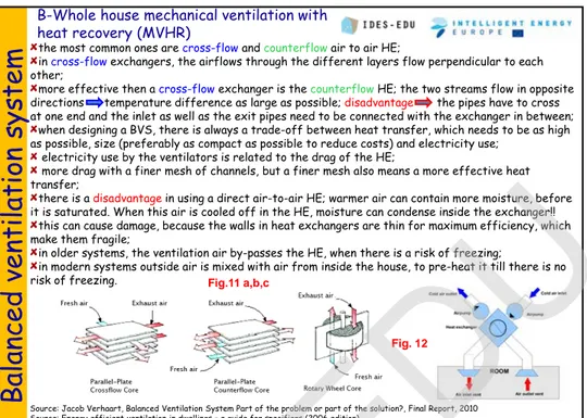
the most common ones are cross-flow andcounterflowair to air HE;
in cross-flowexchangers, the airflows through the different layers flow perpendicular to each other;
more effective then a cross-flowexchanger is the counterflowHE; the two streams flow in opposite directions temperature difference as large as possible; disadvantage the pipes have to cross at one end and the inlet as well as the exit pipes need to be connected with the exchanger in between;
when designing a BVS, there is always a trade-off between heat transfer, which needs to be as high as possible, size (preferably as compact as possible to reduce costs) and electricity use;
electricity use by the ventilators is related to the drag of the HE;
more drag with a finer mesh of channels, but a finer mesh also means a more effective heat transfer;
there is a disadvantagein using a direct air-to-air HE; warmer air can contain more moisture, before it is saturated. When this air is cooled off in the HE, moisture can condense inside the exchanger!!
this can cause damage, because the walls in heat exchangers are thin for maximum efficiency, which make them fragile;
in older systems, the ventilation air by-passes the HE, when there is a risk of freezing;
in modern systems outside air is mixed with air from inside the house, to pre-heat it till there is no risk of freezing.
Balanced ventilation system
B-Whole house mechanical ventilation with
heat recovery (MVHR)
Source: Jacob Verhaart, Balanced Ventilation System Part of the problem or part of the solution?, Final Report, 2010 Source: Energy efficient ventilation in dwellings – a guide for specifiers (2006 edition)
Source: Chiel BOONSTRA, Loes JOOSTEN, TREES Training for RenovatedEnergyEfficient Social housing, Intelligent Energy-Europe programme, contract n°EIE/05/110/SI2.420021, Section 1 – Techniques 1.3 Ventilation
Fig. 12 Fig.11 a,b,c
heat is stored in solid heat batteries metal (mostly aluminium or copper) mesh of small channels, through which the air can flow
the smaller the channels, the larger the surface area for heat transfer, and the larger the aerodynamic drag;
heat wheel a honeycomb mesh made of heat storing material rotates through the two airflows. First heating up in the flow out and then releasing that heat in the incoming flow;
a Kantherm system two heat batteries are stationary and the airflow through them is alternated via a valve. The valve changes the direction of the airflow every 50 s. the first 50 seconds, one of the batteries is loading and the other is releasing heat. The next 50 seconds the roles reverse and the loaded battery releases its heat and the other battery heats up.
Large Heat Recovery Systems
Balanced ventilation system
Source: Jacob Verhaart, Balanced Ventilation System Part of the problem or part of the solution?, Final Report, 2010
Heat wheel
Kantherm system larger systems use solid material in the
heat batteries to temporarily store heat and reverse the airflow from cold to hot the chance of the exchanger getting damaged by freezing of condensation is much lower! Condensation and ice can only built-up for the period of half a cycle!
installations using solid heat batteries have typically a lower overall efficiency, but are better suited for larger ventilation capacities.
16 Fig.14 Fig.13
Fans
provide air for ventilation and industrial processes that need air flow
Source: Advanced Variable Air Volume System design Guide, 2007 Source: www.energyefficiencyasia.org Outlet Diffusers Baffles Heat Exchanger Turning Vanes (typically used on short radius elbows)
Variable Frequency Drive Motor Centrifugal Fan Inlet Vanes Filter Belt Drive Motor Controller
Fans and
Blowers
The factors to consider when
selecting a fan include:
Redundancy
– a single fan
or multiple fans;
Duty
– CFM and static
pressure at design conditions;
First cost
– more efficient
fans are often more
expensive;
Space constraints
– a tight
space may limit fan choices;
Efficiency
– varies greatly
by type and sizing;
Noise
– different fan types
have different acoustic
performance;
Surge
– some fan selections
are more likely to operate in
surge at part-load conditions.
Fig.15
Fans’ laws
Source: Fans & Blowers, Presentation from the “Energy Efficiency Guide for Industry in Asia”, www.energyefficiencyasia.org
Fans and
Blowers
Fig.16
Source: Andrew K. Persily, Manual for Ventilation Assessment in Mechanically Ventilated Commercial Buildings, 1994, Building and Fire Research Laboratory National Institute of Standards and Technology, Gaithersburg, MD 20899
Fans
Fans and
Blowers
Set of Fan Curves System Curve
the performance of a fan is described by a
FAN CURVE
that relates the
static pressure increase across a fan to the airflow rate through the fan at
a constant fan speed in revolutions per minute (rpm).
Air pressure decreases through the ventilation system, and this pressure
drop is equal to the total airflow resistance of all the system components
and the ductwork. This pressure drop depends on the airflow rate and is
described by a
SYSTEM CURVE
The
SYSTEM CURVE
is affected by changes in damper position, dirty
filters, condensation on coils, holes in ductwork and obstruction of outlets or
inlets.
Fig.17 a,b
Interaction Between System and Fan Curves
Fans and
Blowers
Source: Andrew K. Persily, Manual for Ventilation Assessment in Mechanically Ventilated Commercial Buildings, 1994, Building and Fire Research Laboratory National Institute of Standards and Technology, Gaithersburg, MD 20899
The intersection of the system curve and the fan performance curve defines the point at which the pressure across the fan and through the system are equal, and thereby defines the airflow rate;
If the airflow resistance of the system is accurately estimated during the design and the fan is properly selected and installed, then the point of intersection will be at the design airflow rate of the system;
If the system resistance increases, then a new system curve S’ replaces the original system curve S; the fan and system curves will intersect at a higher pressure difference and a lower airflow rate; the airflow rate can be returned to its design value by increasing the fan speed, such that a new fan curve F’ is in effect.
System’s functioning
Fig.17 c
Fans and
Blowers
Source: Advanced Variable Air Volume System design Guide, 2007
Fan classification
Forward
inclined Backward inclined
Roof-top Mixed flow Axial Fig.18 a,b,c,d,e,f
Fans and
Blowers
Source: FAN TYPES, Kruger Technical Bulletin TBN007.0/1998
Fan classification
Fig.19 a
Fans and
Blowers
Source: FAN TYPES, Kruger Technical Bulletin TBN007.0/1998,
Fan classification
Fig.19 b
Fans and
Blowers
Source: FAN TYPES, Kruger Technical Bulletin TBN007.0/1998,
Fan performance & applications
Fig.19 c
Fans and
Blowers
Source: FAN TYPES, Kruger Technical Bulletin TBN007.0/1998,
Fan performance & applications
Fig.19 d
Backward-inclined
Advantages
Operates with changing static pressure Suited for high flow and forced draft services Efficiency >85%
Disadvantages
Not suited for dirty airstreams Instability and erosion risk Radial fans
Advantages
High pressure and temperature Simple design
High durability Efficiency up to 75% Large running clearances
Disadvantages
Suited for low/medium airflow rates only
Source: www.energyefficiencyasia.org
Fans and
Blowers
Centrifugal Fans
Forward curved AdvantagesLarge air volumes against low pressure Relative small size
Low noise level
Disadvantages
Not high pressure / harsh service Difficult to adjust fan output Careful driver selection Low energy efficiency 55-65%
(Canadian Blower)
(Canadian Blower)
Fig.20 a
Vane axial fans
Advantages
Suited for medium/high pressures Quick acceleration
Suited for direct motor shaft connection Most energy efficient 85%
Disadvantages
Expensive Propeller fans
Advantages
High airflow at low pressure Little ductwork
Inexpensive
Suited for rooftop ventilation Reverse flow
Disadvantages
Low energy efficiency Noisy
Source: www.energyefficiencyasia.org
Fans and
Blowers
Axial Fans
Tube axial fans
Advantages
High pressures to overcome duct losses Suited for medium-pressure, high airflow rates Quick acceleration
Space efficient
Disadvantages
Expensive Moderate noise
Low energy efficiency 65%
(Fan air Company)
(Canadian Blower)
Fig.20 b
Differences from fans:
Much higher pressures : 1.20 kg/cm
2Used to produce negative pressures for industrial vacuum
systems
Types
A) Centrifugal blower
B) Positive displacement
Fans and
Blowers
Blowers
A) Centrifugal BlowersGear-driven impeller that accelerates air Single and multi-stage blowers
Operate at 0.35-0.70 kg/cm2 pressure Airflow drops if system pressure rises
B) Positive displacement
Rotors trap air and push it through housing
Constant air volume regardless of system pressure
Suited for applications prone to clogging
Turn slower than centrifugal blowers Belt-driven for speed changes
Source: www.energyefficiencyasia.org
Source : www.enginemechanics.com
Fig.20 c
Fig.21
29
Source: Chapter 7 of the 1997 ASHRAE Handbook- HVAC Fundamentals Source: Chapter 46 of the 1999 ASHRAE Handbook— Applications
Basic Acoustic Terminology
Typical Paths in HVAC Systems THE SELECTION of mechanical
equipment and the design of
equipment spaces should be
undertaken with an emphasis on: (1) the intended uses of the equipment;
(2) the goal of providing acceptable sound and vibration levels in occupied spaces of the building in which the equipment is located.
NOISE propagates from the
sources through the air
distribution ducts, through the structure, and through combinations of paths, reaching the occupants. All mechanical components,
from dampers to diffusers to junctions, may produce sound by the nature of the airflow through and around them..
Adequate noise and vibration control in a heating, ventilating, and air-conditioning (HVAC) system is not difficult to achieve during the design phase of the system, providing basic noise and vibration control principles are understood
Fig.22
Source: Chapter 7 “SOUND AND VIBRATION” of the 2005 ASHRAE Handbook Fundamentals (SI) Source: Chapter 46 of the 1999 ASHRAE Handbook— Applications
Basic Acoustic Terminology
ACOUSTICAL DESIGN OBJECTIVE
the primary objective of HVAC system and equipment acoustical design is
to create an appropriate acoustical environment for a given space. Sound and
vibration are created by a
source, are transmitted along one or more paths,
and reach a receiver
;
treatments
and modifications can be applied to any or all of these
elements to achieve a proper acoustical environment that is free of noise and
vibration.
SOUND
a traveling oscillation in a medium exhibiting the properties of both elasticity and inertia’
in fluid media (air or water), the disturbance travels as a longitudinal compression wave;
sound is generated by a vibrating surface or a turbulent fluid stream.
the speed of a longitudinal wave in a fluid medium is a function of the medium’s density and modulus of elasticity; in air at room temperature, the speed of sound is about 340 m/s; in water, about 1500 m/s;
frequency is the number of oscillations (or cycles) per unit time completed by a vibrating object. The international unit for frequency is cycles/s or hertz (Hz);
wavelength is the distance between successive rarefactions or compressions of the propagation medium. Wavelength, speed, and frequency are interrelated by the following equation:
f
c
=
λ
IDES-EDU
31
Basic Acoustic Terminology
Noise
the first and simplest definition of noise is
any
unwanted sound
.
the second definition of noise is broadband sound
without distinguishable frequency characteristics,
such as the sound of a waterfall.
three types of noise in the second context are
frequently encountered in acoustics:
1.
Random noise is an oscillation
, the instantaneous magnitude of
which is not specified for any given instant. The instantaneous magnitudes
of a random noise are specified only by probability distributions, giving
the fraction of the total time that the magnitude, or some sequence of
magnitudes, lies within a specified range;
2
. White noise
has a continuous frequency spectrum with equal
energy/Hz over a specified frequency range. In this sense, it is like white
light. White noise is not necessarily random.
3.
Pink noise
also has a continuous frequency spectrum but has equal
energy per constant-percentage bandwidth
Source: Chapter 7 “SOUND AND VIBRATION” of the 2005 ASHRAE Handbook Fundamentals (SI) Source: Chapter 46 of the 1999 ASHRAE Handbook— Applications
32
Basic Acoustic Terminology
HUMAN RESPONSE TO SOUND
any unwanted sound!
Sound becomes noise when it:• is too loud—the sound is uncomfortable or makes
speech difficult to understand;
• is unexpected (e.g., the sound of breaking glass);
• is uncontrolled (e.g., a neighbor’s lawn mower);
• happens at the wrong time (e.g., a door slamming
in the middle of the night);
•
contains unwanted pure tones (e.g., a whine, whistle, or hum);
• contains unwanted information or is distracting (e.g., an adjacent
telephone conversation or undesirable music);
• is unpleasant (e.g., a dripping faucet);
• connotes unpleasant experiences (e.g., a mosquito buzz or a siren wail);
• is any combination of the previous examples!
Source: Chapter 7 of the 1997 ASHRAE Handbook- HVAC Fundamentals
Decibel
basic unit of measurement in acoustics;
numerically, the decibel is 10 times the base 10 logarithm of the ratio of
two like quantities proportional to acoustical power or energy;
the term
level, when used in relation to sound power, sound
intensity, or
sound pressure, indicates that dB notation is being used.
Sound Power and Sound Power Level
A fundamental characteristic of an acoustic source is its ability to radiate
energy, whether it is weak and small in size (a cricket) or strong and large (a
compressor);
Sound power and sound pressure are expressed in dB - as a ratio relative to
some reference level.
Sound Power Level PWL in dB:
W
refis 10-12 W
W
sourceis sound power in W.
Sound Pressure Level SPL in dB:
P
ref= 2 . 10-5 Pa
P = sound pressure in Pa
For ducts with no attenuation, sound pressure propagation is 1-dimensional
and the SPL is constant.
Source: Chapter 7 of the 1997 ASHRAE Handbook- HVAC Fundamentals Source: Chapter 46 of the 1999 ASHRAE Handbook— Applications
PWL = 10 log
10(W
source/W
ref)
SPL = 10 log
10( P2 / P
ref2)
Basic Acoustic Terminology
TERMINOLOGY
dB; dBA;
The ear also responds in a non-linear way, with maximum sensitivity
around 2 or 3 kHz and much lower sensitivity at low frequencies. A
commonly used metric is the A-weighted dB (dBA) which is weighted
according to the typical human ear's frequency response.
L
eq; L
A10; L
A90L
eqis the time averaged sound pressure level and is used for
time-varying signals.
L
A10is the SPL which is exceeded for 10% of the time.
L
A90is the SPL which is exceeded for 90% of the time (the
"background" level).
34
TERMINOLOGY
Basic Acoustic Terminology
Absorption and insulation
Absorption Coefficient:
Normalized Level Difference DnT in dB(A) between 2 zones:
Sound Reduction Index R in dB(A) of a surface:
Reverberation time Tr (s)
A = Σi αi.Si
D
nT= L
1– L
2+ 10.log ( Tr / T
0)
R = L
1– L
2+ 10.log ( S / A )
Tr = 0.161V / A
Sabine’s formula
Source: Isolation acoustique bâtiments (Florent Cappoen)
35
Noise sources
TYPICAL SOURCES OF NOISE
Rotating and reciprocating equipment such as fans, motors, pumps, and chillers; noise generated by vortices shed at the trailing edges of fan blades can be tonal;
turbulence generated upstream of the fan and ingested into the fan is the source of broadband noise;
turbulence in the boundary layer on the surface of fan blades also causes broadband noise;
flow that separates from blade surfaces can cause low-frequency noise; nonuniform inflow to fans, created by obstructions, can produce tonal noise at frequencies of blade;
fan imbalance produces vibration at frequencies of shaft rotation and multiples; these low-frequency vibrations can couple to the structures to which the fan is attached, which can transmit the vibration over long distances and radiate low-frequency noise into rooms;
air and fluid sounds, such as those associated with flow through ductwork, piping systems, grilles, diffusers, terminal boxes, manifolds, and pressure-reducing stations;
flow inside ducts is often turbulent, which is a source of broadband noise;
sharp corners of elbows and branches can separate flow from duct walls, producing low-frequency noise;
excitation of surfaces (e.g., friction); movement of mechanical linkages; turbulent flow impacts on ducts, plenum panels, and pipes; and impacts within equipment, such as cams and valve slap;
Source: Chapter 7 of the 1997 ASHRAE Handbook- HVAC Fundamentals
` Central Plant
` fans: axial fans generally have lower noise output than centrifugal fans except at low frequencies;
` uniform flow into or out of a fan is rare in typical field applications; ` avoid locating duct turns near the inlet or discharge of a fan;
` components such as dampers and silencers installed close to fan equipment can produce nonuniformities in the velocity profile at the entrance to the silencer, which results in a significantly higher-than-anticipated pressure drop across that component;
` well-designed damper or silencer can actually improve flow conditions, which may reduce noise levels.
` Noise in Airflow Systems
` larger diameter ducts - lower air velocity, less noise; ` diffusers - data from manufacturer;
` External Noise
` road traffic, aircraft, rail, industrial sources, external equipment and plant
Noise sources
HOW TO ATENUATE NOISE?
Air distribution system noise can be controlled by one or both of the
following strategies:
1. Reduce sound power levels at the source (the fan and turbulence induct
systems).
2. Attenuate sound generated by the noise sources.
37
Design criteria
BASIC DESIGN TECHNIQUES
Source: Chapter 46 of the 1999 ASHRAE Handbook— Applications
1. Design the air distribution system to minimize flow resistance and
turbulence. High flow resistance increases the required fan pressure, which
results in higher noise being generated by the fan. Turbulence increases the
flow noise generated by duct fittings and dampers in the air distribution
system, especially at low frequencies.
2. Select a fan to operate as near as possible to its rated peak efficiency
when handling the required quantity of air and static pressure. Also, select a
fan that generates the lowest possible noise but still meets the required
design conditions for which it is selected. Using an oversized or undersized
fan that does not operate at or near rated peak efficiency can result in
substantially higher noise levels.
3. Design duct connections at both the fan inlet and outlet for uniform and
straight air flow. Failure to do this can result in severe turbulence at the fan
inlet and outlet and in flow separation at the fan blades. Both of these can
significantly increase the noise generated by the fan.
4.
Select duct silencers that do not significantly increase the required fan
total static pressure. Duct silencers can significantly increase the required
fan static pressure if improperly selected. Selecting silencers with static
pressure losses of 87 Pa. or less can minimize silencer airflow regenerated
noise.
5. Place fan-powered mixing boxes associated with variable-volume air
distribution systems away from noise-sensitive areas.
38
Design criteria
BASIC DESIGN TECHNIQUES
Source: Chapter 46 of the 1999 ASHRAE Handbook— Applications
6. Minimize flow-generated noise by elbows or duct branch takeoffs,
whenever possible, by locating them at least four to five duct diameters
from each other. For high velocity systems, it may be necessary to increase
this distance to up to ten duct diameters in critical noise areas.
7.
Keep airflow velocity in the duct as low as possible (7.5 m/s or less) near
critical noise areas by expanding the duct cross-section area. Flow
separation, resulting from expansion angles greater than 15°, may produce
rumble noise. Expanding the duct cross-section area will reduce potential
flow noise associated with turbulence in these areas.
8. Use turning vanes in large 90° rectangular elbows and branch takeoffs.
9.
Place grilles, diffusers and registers into occupied spaces as far as
possible from elbows and branch takeoffs.
10. Minimize the use of volume dampers near grills, diffusers and registers in
acoustically critical situations.
11.
Vibration isolate all vibrating reciprocating and rotating equipment if
mechanical equipment is located on upper floors or is roof-mounted. Also, it
is usually necessary to vibration isolate the mechanical equipment that is
located in the basement of a building as well as piping supported from the
ceiling slab of a basement, directly below tenant space. It may be necessary
to use flexible piping connectors and flexible electrical conduit between
rotating or reciprocating equipment and pipes and ducts that are connected
to the equipment.
39
Design criteria
BASIC DESIGN TECHNIQUES
Source: Chapter 46 of the 1999 ASHRAE Handbook— Applications
12. Vibration isolate ducts and pipes, using spring and/or neoprene hangers
for at least the first 15 m from the vibration-isolated equipment.
13.
Use barriers near outdoor equipment when noise associated with the
equipment will disturb adjacent properties if barriers are not used. In normal
practice, barriers typically produce no more than 15 dB of sound attenuation
in the mid frequency range.
Sound Rating Methods
a-weighted sound pressure level (dBA)
a single-number measure of the relative loudness of noise that is used extensively in outdoor environmental noise standards
a-weighted sound levels can be measured with simple sound level meters tangent noise criteria (NC)
a single-number rating that is somewhat sensitive to the relative loudness and speech interference properties of a given noise spectrum;
room criteria (RC)
a family of criterion curves and a rating procedure balanced noise criteria (NCB)
used to specify or evaluate room noise and includes noise due to occupant activities
new RC Mark II
is intended for rating the sound performance of an HVAC system as a whole
separation efficiency - ability to retain synthetic standard dust; weight
and % statement;
blacking efficiency - capability to retain atmospheric dust; optical
measured and % statement;
particle separation efficiency - capability to retain particles at fixed
sizes; particle concentration measured and % statement;
dust accumulation capacity - capability to keep standard dust before
the pressure drop extend a certain value;
airflow resistance and static pressure drop of the filters.
40
Source: www.energyefficiencyasia.org
Air filters
CLASIFICATION
TYPES OF AIR CLEANERS
fibrous media unit filters
, in which the accumulating dust load causes
pressure drop to increase up to some maximum recommended value;
renewable media filters
, in which fresh media is introduced into the
airstream as needed to maintain essentially constant resistance and,
consequently, constant average efficiency;
electronic air cleaners
, which, if maintained properly by regular
cleaning, have relatively constant pressure drop and efficiency;
combination air cleaners
, which combine the above types.
Source: Chapter 24 of the 2000 ASHRAE Handbook— Systems and Equipment
41
Air filters
CLASIFICATION
AIR WASHERS
DRY FILTERS
water jets
porous medium
STATIONARY FILTERS ROTARY FILTERS
with automatic cleaning
perforated sheets
zigzag sheets
Source: B. Purushothama , Humidification and ventilation management in textile industry, Woodhead Publishing India (P) Ltd, 2009
Fig.23
Air filters
TYPES AND PERFORMANCE
Source: Chapter 24 of the 2000 ASHRAE Handbook— Systems and Equipment
VISCOUS IMPINGEMENT FILTERS
panel filters
made up of coarse fibers with a high porosity;the filter media are coated with a viscous substance, such as oil which causes particles that impinge on the fibers to stick to them;
design air velocity through the media is usually in the range of 1 to 4 m/s;
low pressure drop, low cost, and good efficiency on lint but low efficiency on normal atmospheric dust!
this type of filter is commonly used in residential furnaces and air conditioning and is often used as a pre-filter for higher-efficiency pre-filters.
DRY EXTENDED-SURFACE FILTERS
media of random fiber mats or blankets of varying thicknesses, fiber sizes, and densities;
media in these filters are frequently supported by a wire frame in the form of pockets, or V-shaped or radial pleats;
efficiency is usually higher than that of panel filters, and the variety of media available makes it possible to furnish almost any degree of cleaning efficiency desired;
media velocities range from 0.03 to 0.5 m/s, although approach velocities run to 4 m/s.
Fig.24
Air filters
TYPES AND PERFORMANCE
Source: Chapter 24 of the 2000 ASHRAE Handbook— Systems and Equipment
VERY HIGH-EFFICIENCY DRY FILTERS
HEPA (high-efficiency particulate air) filters ULPA (ultralow-penetration air)
filters are made in an extended-surface configuration of deep space folds of submicrometre glass fiber paper;
operate at duct velocities near 1.3 m/s, with resistance rising from 120 to more than 500 Pa over their service life;
are the standard for clean room, nuclear, and toxic particulate applications.
MEMBRANE FILTERS
are used mainly for air sampling and specialized small-scale applications where their particular characteristics compensate for their fragility, high resistance, and high cost;
available in many pore diameters and resistances and in flat sheet and pleated forms.
ELECTRET FILTERS
composed of electrostatically charged fibers;
the charges on the fibers augment collection of smaller particles by interception and diffusion (Brownian motion) with Coulomb forces caused by the charges;
there are three types of these filters: resin wool, electret, and an electrostatically sprayed polymer;
efficiency of charged-fiber filters is determined by both the normal collection mechanisms of a media filter and the strong local electrostatic effects;.
Air filters
TYPES AND PERFORMANCE
Source: Chapter 24 of the 2000 ASHRAE Handbook— Systems and Equipment
RENEWABLE-MEDIA FILTERS
(1) moving curtain viscous impingement filters
the resistance remains approximately constant as long as proper
operation is maintained. A resistance of 100 to 125 Pa at a face
velocity of 2.5 m/s is typical of this class;
(2) moving-curtain dry media roll filter
operating duct velocities near 1 m/s are generally lower than those
of viscous impingement filters
ELECTRONIC AIR CLEANERS
can remove and collect airborne contaminants with an initial
efficiency of up to 98% at low airflow velocities (0.8 to 1.8 m/s)
when tested according to ASHRAE Standard 52.1;
Efficiency decreases:
(1) as the collecting plates
become loaded with particulates
(2) with higher velocities
(3) with nonuniform velocity.
Fig.25
45
SELECTION AND MAINTENANCE
Air filters
the following factors should be considered: • Degree and type of air cleanliness required • Disposal of dust after it is removed from the air • Amount and type of dust in the air to be filtered • Operating resistance to airflow (pressure drop) • Space available for filtration equipment • Cost of maintaining or replacing filters • Initial cost of the system
The performance of different filter media is normally as follows:
●
Flat panel type (disposable filters): air velocity 0.1–1.0 m s-1, resistance 25–250 N m-2, efficiency 20–35%●Continuous roll (self cleaning filters): air velocity 2.5 m s-1, resistance 30–175 N m-2, efficiency 25%
●Bag filters: efficiency 40–90%
●HEPA filters: efficiency 99.97% for 0.3 micron particles and larger ●ULPA filters: efficiency 99.9997 for 0.12 micron particles or larger
●Viscous filters panel type (cloth with viscous fluid coating: washable or disposable); plates about 500 × 500 mm, air velocity 1.5–2.5 m s-1, resistance 20–150 N m-2
●Viscous filters (Continuous roll - continuously moving, self cleaning). Air velocity 2.5 m s-1, resistance 30–175 N m-2
•Electrostatic precipitators. Cleaned automatically, air velocity 1.5–2.5 m s-1, resistance negligible, efficiency 30–40%
●Absolute. Dry panel with special coating: disposable or self cleaning, air velocity 2.5 m s-1, resistance 250–625 N m-2
Source: Chapter 24 of the 2000 ASHRAE Handbook— Systems and Equipment
Source: B. Purushothama , Humidification and ventilation management in textile industry, Woodhead Publishing India (P) Ltd, 2009
Fig.26
46
References
VENT Dis.Course, Distant learning vocational training material for the promotion of best practice ventilation energy performance in buildings Module 3: Energy Efficient Mechanical Ventilation
Guide pratique “La ventilation méchanique des habitation”
Energy efficient ventilation in dwellings – a guide for specifiers (2006 edition)
Marion Russell, Max Sherman and Armin Rudd, Review of Residential Ventilation Technologies , Ernest Orlando Lawrence, Berkeley National Laboratory, 2005
Dr. Sam C. M. Hui, Department of Mechanical Engineering, The University of Hong Kong, lecture Mechanical and Natural Ventilation”, 2011
Judy A. Roberson, Richard E. Brown, Jonathan G. Koomey, Steve E. Greenberg, Recommended ventilation strategies for energy-efficient production homes, 1998
Jacob Verhaart, Balanced Ventilation System Part of the problem or part of the solution?, Final Report, 2010
Chiel BOONSTRA, Loes JOOSTEN, TREES Training for Renovated Energy Efficient Social housing, Intelligent Energy-Europe programme, contract n°EIE/05/110/SI2.420021, Section 1 – Techniques 1.3 Ventilation
Advanced Variable Air Volume System design Guide, 2007
Fans & Blowers, Presentation from the “Energy Efficiency Guide for Industry in Asia”
ww.energyefficiencyasia.org
47 Andrew K. Persily, Manual for Ventilation Assessment in Mechanically Ventilated Commercial Buildings, 1994, Building and Fire Research Laboratory National Institute of Standards and Technology, Gaithersburg, MD 20899
FAN TYPES, Kruger Technical Bulletin TBN007.0/1998
www.enginemechanics.com
Chapter 7 of the 1997 ASHRAE Handbook- HVAC Fundamentals Chapter 46 of the 1999 ASHRAE Handbook— Applications
Chapter 7 “SOUND AND VIBRATION” of the 2005 ASHRAE Handbook Fundamentals (SI) Florent Cappoen, Isolation acoustique bâtiments
Chapter 24 of the 2000 ASHRAE Handbook— Systems and Equipment
B. Purushothama , Humidification and ventilation management in textile industry, Woodhead Publishing India (P) Ltd, 2009
References
48 48
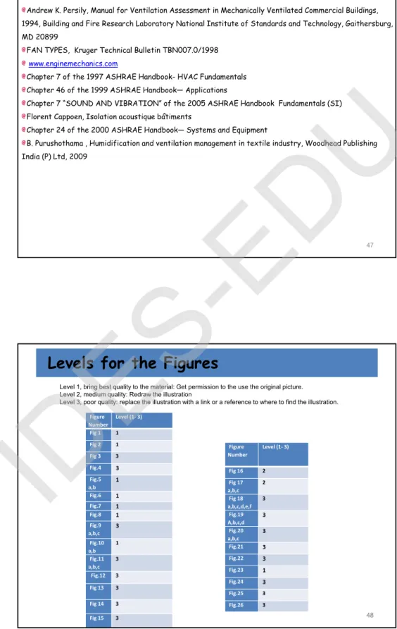
Levels for the Figures
Figure Number Level (1‐ 3) Fig 1 1 Fig 2 1 Fig 3 3 Fig.4 3 Fig.5 a,b 1 Fig.6 1 Fig.7 1 Fig.8 1 Fig.9 a,b,c 3 Fig.10 a,b 1 Fig.11 a,b,c 3 Fig.12 3 Fig 13 3 Fig 14 3 Fig 15 3
Level 1, bring best quality to the material: Get permission to the use the original picture. Level 2, medium quality: Redraw the illustration
Level 3, poor quality: replace the illustration with a link or a reference to where to find the illustration.
Figure Number Level (1‐ 3) Fig 16 2 Fig 17 a,b,c 2 Fig 18 a,b,c,d,e,f 3 Fig.19 A,b,c,d 3 Fig.20 a,b,c 3 Fig.21 3 Fig.22 3 Fig.23 1 Fig.24 3 Fig.25 3 Fig.26 3