1
Author Accepted Manuscript
Link to Publisher:
https://www.sciencedirect.com/science/article/pii/S0264127517310705?via%3Dihub
DOI: https://doi.org/10.1016/j.matdes.2017.11.039
Influence of micro-notches on the fatigue strength and crack propagation of unfilled and short carbon fiber reinforced PEEK
A. Avanzini*, C. Petrogalli, D. Battini, G. Donzella
Department of Mechanical and Industrial Engineering, University of Brescia,
Via Branze, 38 25123 Brescia (Italy). *corresponding author: [email protected]
Abstract
Short carbon fiber reinforced (SCFR) PEEK is a highly attractive material for lightweight structures; improving knowledge about the influence of local imperfections on its fatigue behavior is essential for the design of real components. To this aim, fatigue strength and crack propagation of two grades of SCFR PEEK and neat matrix were investigated by testing at different stress levels specimens with a micro-notch consisting of a small blind hole (range diameter 0.1- 1 mm). Overall, the presence of a micro-notch resulted in a decrease of fatigue strength compared to un-notched condition, but with different sensitivity and crack propagation patterns; while a higher fiber volume fraction enhanced fatigue strength and resistance to crack propagation, the combination of a lower fiber content and inclusion of additive particles had a negative effect. Crack propagation in the notched region was also evaluated. The average values of Paris' law exponential coefficients were similar and within the range of literature values, without apparent correlation with reinforcement type. Preliminary investigations in the presence of the smallest micro-notches seem to indicate the presence of a threshold size below which the influence of a small notch is comparable with that of material inherent defects, but further testing is necessary.
2
Keywords: Short Carbon fiber; PEEK; Fatigue; Micro-Notch1. Introduction
Polyetheretherketone (PEEK) exhibits excellent mechanical properties, even under continuous service conditions at elevated temperatures, in addition to good chemical resistance in many environments. The inclusion of reinforcement phases, such as fibers or other special fillers, can further enhance the
mechanical properties of PEEK. Short fiber reinforced (SFR) PEEK composites are particularly attractive for a variety of weight sensitive applications, because safety critical components can be manufactured taking advantage of their excellent mechanical properties combined with ease of processing and the lower costs traditionally associated with thermoplastics manufacturing processes. Quite obviously, in order to fully take advantage of the potential benefits achievable with this class of materials, knowledge of fatigue behavior is essential. The fatigue behavior of PEEK has received considerable attention and different types of investigations were reported in literature, both for unfilled matrix and reinforcement with short fibers. Considering unfilled PEEK, Berer et al. [1] carried out tensile fatigue tests at high loads to investigate changes in the dynamic mechanical response of PEEK in the high stress tensile regime. Shrestha et al. [2] investigated the cyclic deformation and fatigue considering uniaxial fully-reversed cyclic tests with different control modes (i.e. strain-controlled and load-controlled) and varying frequency and strain amplitude. They also compared fatigue life predictions for PEEK using the Coffin-Manson equation, Smith-Watson-Topper (SWT) parameter and energy based approach. Fatigue life prediction criteria for PEEK in a multiaxial loading condition were instead considered in [3]; in this study, fatigue tests were carried out under strain-controlled fully reversed uniaxial tension–compression, cyclic torsion and axial–torsion. Aspects related to fatigue crack growth were considered in [4], whereas more recently the effects of micro-structural inclusions were studied to develop a microstructure-sensitive fatigue model to predict the fatigue life of PEEK [5]. The model included both crack incubation and small crack growth regimes. The fatigue life of PEEK at higher strain amplitudes was found to be dominated by a short crack growth regime, rather than the crack initiation. In contrast, a larger portion of fatigue life was spent in the crack initiation regime at the lower strain amplitudes. Methods to characterize the crack growth
kinematics of non-reinforced, semi-crystalline thermoplastic polymers such as PEEK were instead analyzed in [6]. Considering SCFR PEEK, stress-life curves (S-N) were reported by the authors of the present study in a previous research [7], in which the fatigue behavior of PEEK reinforced with short
3
carbon fibers was investigated in relation to cyclic damage modeling. In the past, the effect of reinforcing PEEK with short fibers on fatigue crack propagation was also investigated taking into consideration micro-structural details as well as processing variables [8-10]. Fatigue crack resistance showed a complex interdependence of various matrix related factors, such as molecular weight and crystallinity, and fiber type, length, aspect ratio and preferred orientation. Overall, due to its highly heterogeneous nature, the fatigue behavior of SFR PEEK cannot be considered as completely understood, since many factors may influence failure mechanics in the presence of cyclic loading. These include micro-structural features of reinforcement phase (i.e. fiber length and orientation), self-heating and dissipative response of the matrix and loading conditions (i.e. mean stress, frequency, environmental effects), as remarked in [11], where the interested reader can find a comprehensive review of past investigations on SFR polymer composites. When designing components made of SFR composites, another important aspect to be considered is the influence of notches or defects on fatigue response. The increasing use of this type of materials to manufacture structural components, in which grooves, notches or small scratches may be present, motivated investigations in this field. For short-glass fiber reinforced polyamide, a comparison of unnotched response in the presence of mild or sharp notch can be found in [12]. More recently, for the same type of SFR composite, damage initiation [13] and mechanisms [14] were investigated considering specimens with different fiber volume fraction, in which the notch consisted of a central slit of 10 mm with notch radius of 0.2 mm. A neat thermoplastic (polypropylene impact co-polymer) and athermoplastic composite made of polybutylene terephthalate (PBT) with 30 wt% short glass fibers were instead used for the experimental study conducted in [15], in which notched specimen with 2-mm hole were subjected to variable amplitude loading. On the other hand, for unfilled and short carbon fiber reinforced PEEK, very limited data are available concerning this aspect. In particular, for unfilled PEEK, stress-life (S-N) fatigue and fracture behavior in the presence of notches were examined only in [16], considering tension-tension loading of circumferentially grooved round bar specimens with different elastic stress concentration factors. An interesting finding in this study was that the majority of the lifetime was spent in crack initiation, and that the ratio between the number of cycles for crack initiation and the total appeared to increase as the total number of cycles increased. These authors concluded that there could be the potential for gross failure of PEEK devices without any substantial period of detectable difference in structural behavior, indicating the necessity of considering design-related stress
concentrations carefully when using PEEK. For SCFR-PEEK rotating-bending fatigue tests on plain and notched specimens were carried out by Nisitani et al. [17] to compare notch sensitivity of neat and short
4
carbon-fiber reinforced PEEK. In the presence of a small hole (diameter 0.1 mm, depth 0.1mm) neat PEEK exhibited a higher sensitivity of fatigue strength to a notch and very high fatigue crack growth rate compared to reinforced material. Overall, the influence of local variations like those induced by scratches, notches, voids or imperfections for SFR PEEK composites cannot be considered as completelyunderstood, due to the limited information available. Contrary to unfilled polymers, these materials are full of impurities and local inherent micro-notches, caused by weak adhesion between filler and matrix. Depending on the specific nature of SFR composite constituents, such local imperfections could have a significantly different influence on fatigue lifetime, especially when compared to the effects of inherent notches present in the material. The lack of data for examined materials and their importance from a design point of view thus motivated the present study, whose main novel aspects include comparison between different types of PEEK composites and the set-up of an original non-standard procedure to allow quantitative evaluation of results. In particular micro-notch sensitivity of unfilled PEEK was compared with two types of SCFR PEEK, differing by weight fraction of carbon short fibers and addition of fillers like graphite and PTFE. From a methodological point of view, the influence of micro-notches, which could actually be present in the material in a variety of shapes and dimensions, was evaluated by drilling small blind holes of different diameters and depth on the surface of fatigue tested specimens and monitoring cyclic crack growth with a semi-automated procedure. In this way, different notching conditions could be compared in a repeatable manner. New relevant data concerning fatigue strength and crack propagation for this important class of material were obtained, providing interesting insights on the influence of micro-notches as a function of material heterogeneity.
2. Methods
2.1. Materials, specimens and test procedure
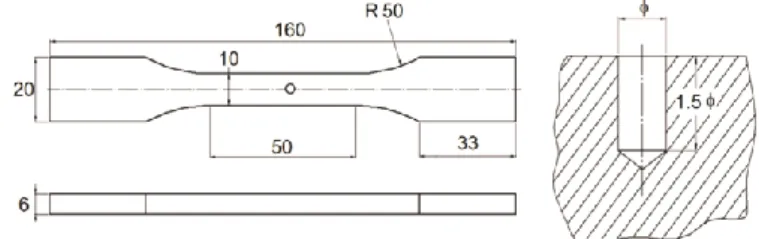
For comparison purposes, three different PEEK based materials were examined. They will be referred to in the text as Neat (unfilled grade PEEK), CF10-PVX (PEEK filled with 10% wt. carbon micro-fibers, graphite and PTFE) and CF30 (PEEK filled with 30% wt. carbon micro-fibers). Neat PEEK was included in the study as a reference material, representative of matrix properties. CF10-PVX is mainly employed in applications in which tribological aspects are relevant, due to the action of PTFE and graphite as internal lubricants. In particular, graphite improves frictional behavior whereas the incorporation of PTFE reduces the friction coefficient and improves load carrying capacity under sliding conditions. CF30 incorporates a higher amount of reinforcing fibers for use in structural applications. Dog-bone shaped specimens (Fig. 1)
5
were machined from semi-finished extruded plates available commercially. Notched specimens were obtained by drilling blind micro-holes on the surface of the specimen, as schematically shown in Fig. 1, in the center of the specimen gage region. Nominal hole diameters of 0.4 and 1 mm were considered, with depth equal to 1.5 diameter value. The effective size, depth and position of the micro-hole were checked for each specimen at the end of the test, by observation of the fractured surface at the microscope. Load-controlled tension-tension fatigue tests were conducted on servo-hydraulic testing machine (INSTRON 8501). Tests were interrupted upon reaching 106 cycles, in case failure did not occur before. Sinusoidal pulsating cycles with loading ratio R equal to 0.1 were imposed considering various maximum stress levels.Fig. 1. Micro-notch geometry and specimen example.
Ideally, for comparison purposes, the three materials should be tested with the same maximum stresses, but previous investigations on plain specimens [7] revealed that fatigue strength of specific materials under examination can be quite different. Thus, in order to investigate stress conditions that may lead to failure in presence of notches, different ranges of maximum applied stress were considered for each material. A summary of the combinations of load and micro-notches considered for each material is reported in Tab. 1.
Neat PEEK CF10-PVX CF30
Micro-hole [mm] (0.1) 0.4 1 (0.1) 0.4 1 (0.1) 0.4 1
N° spec. 1 7 10 3 7 7 - 7 6
Stress [MPa] 80 50-85 55-90 50-60 37.5-60 35-60 - 90-130 80-115 Tab. 1 Test Summary
2.2. Crack growth measurement
During the tests, crack nucleated from the circumferential edge of the micro-holes and a key aspect of the experimental procedure consisted in monitoring cyclic crack propagation from the artificial micro-notches. The set-up for image acquisition consisted of a high-resolution camera (Nikon D3200) equipped with a macro lens, recording full HD videos at 50 fps of the micro-hole region. For the smallest notches,
6
additional close-up lenses were mounted to increase resolution of the image in this area. In order to better appreciate crack propagation during the test, on the black surfaces of CF30 and CF10-PVX specimens a white painting was locally applied over a small band near the micro-hole (see Fig. 2). Crack propagation was evaluated by computing crack total length as the sum of hole diameters and lateral cracks, as observed on the surface of the notched specimen.The total length of the crack (L) was measured by means of in-house developed scripts for digital image processing of acquired images and automated crack presence recognition and length calculation. In particular, each video was analyzed through the following main steps:
- Splitting original videos (approximate duration 20 min. each) into fragments of shorter duration to reduce computational effort
- Extracting frames from each fragment, synchronizing timing with associated loading cycle number - Calculating conversion factor from pixel to mm
- Processing each single frame using in-house developed tools for digital image analysis (see Fig. 2) and overall length calculation
Fig. 2. (a) Crack on the surface of the notched specimen and scheme for calculation of crack length (b) Sequence of image processing steps for crack length evaluation.
2.3. Stress intensity factor
As discussed in next paragraph 3.1, microscopic observation of fractured surfaces revealed that in most cases the area interested by crack propagation had an approximately semi-elliptical shape. The presence of a crack propagation area around the micro-notches suggests that by applying fracture mechanics concepts, further insights on the fatigue behavior of the materials could possibly be gained. In particular, once information about crack length as a function of cycle number is available, fatigue crack propagation curves could be used to characterize fatigue behavior. To this aim, it is first necessary to define a stress intensity factor KI for the present test configuration. Such a definition is not obvious, since in the initial
7
configuration the defect introduced in the specimen is actually a micro-notch and not a sharp crack. Assuming, as a first approximation, that the initial notch could also be regarded as a semi-ellipse, with semi-axes a and c (see Fig. 3), KI could be estimated with eq. (1), using the approach described in [18] for semi-elliptical surface cracks in a plate with finite width:(1)
Factor Q depends on the ratio a/c, whereas coefficient Fs depends also on plate thickness (t) and width (w), as well as on the angular position considered along the ellipse.
Fig. 3. Definition of crack dimensions.
For the examined configuration the maximum value of KI was found at the intersection between surface and ellipse. Then, the typical fatigue crack growth behavior of a given material under certain condition can be represented by applying the well-known Paris' law (eq. 2):
(2)
in which crack propagation rate (dL/dN) is related to the stress intensity factor range (KI), C and m being parameters depending on material properties and test variables. Of course, in order to use the definition of stress KI previously given (i.e. eq.1), it is necessary to take into account that the dimensions of the crack change during the test, as well as coefficients Fs and Q which depend on the ratios a/c and
a/t. Therefore, the length of the semi-axes a and c have to be determined during the test. The dimension 2c corresponds to the total crack length L measured on the observable specimen surface. The value of a
cannot be measured during the test.
Therefore, it was estimated assuming that it increased from an initial value (i.e. a0, equal to machined
micro-hole depth) to its final length (measurable on fracture surfaces), with the same proportion as total crack length increased from initial dimension (i.e. 2co, micro-hole diameter) to its length at failure. To
this aim at the end of the test, each fracture surface was analyzed by means of optical microscope to check effective dimensions of the notch and to measure the size of the fracture surface around it.
8
3. Results3.1. Fracture surfaces
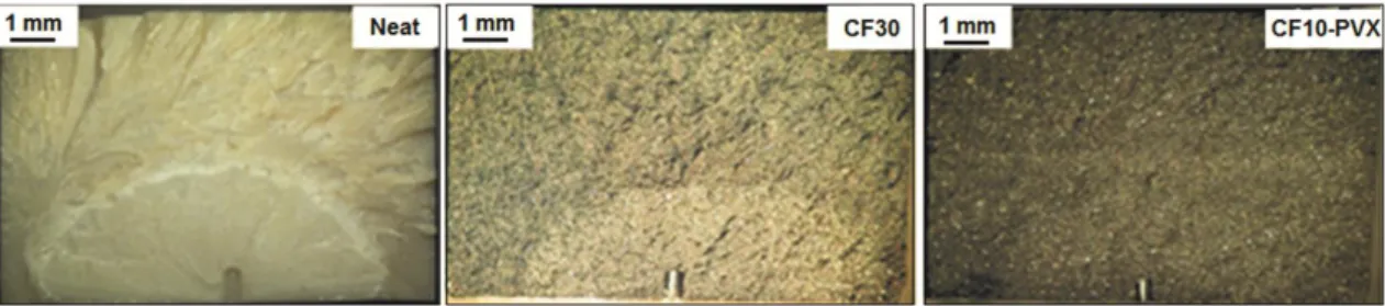
The fracture surfaces of micro-notched specimens were observed with an optical microscope. A comparative example of their typical aspect for each material is reproduced in Fig. 4. Considering neat PEEK, a crack propagation region expanding radially from the notch is clearly noticeable. Two distinct regions could be noticed for CF30 as well, suggesting the presence of an area where crack propagated around the micro-hole. For CF10-PVX, although the progression of cracks from the notch could be clearly appreciated observing the frontal surface of the specimen during the test, the extension of the crack propagation region was more difficult to clearly identify, although an area with slightly different appearance in terms of color and texture could be noticed. A possible interpretation of such different aspects could be that the more the material is full of “impurities”, as fillers and short fibers in CF10-PVX, the more these could act as preferential crack nucleation points distributed in the region where stress state is perturbed by the notch.
Fig. 4. Fracture surfaces.
3.2. Fatigue life curves
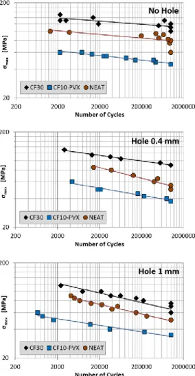
Fatigue life curves for examined materials with micro-notched configurations are reported in Fig. 5, in which maximum applied fatigue stress (max) is plotted vs. number of cycles to failure (Nf). The results of fatigue testing are also reported in Tab. A1 and Tab. A2 in the appendix.
Results from previous investigations on plain specimen (i.e. no hole) [7] are included for comparison purposes. For both plain and notched specimens fatigue strength changed significantly depending on the type of reinforcing phase. By comparison of the three materials, the main finding is that when PEEK is reinforced with short fibers only and with higher fiber weight fraction (i.e. CF30), the mechanical properties of the matrix are enhanced by the strengthening effect provided by the reinforcing phase. On the contrary, in the presence of reduced fiber content and filler inclusion (i.e. CF10-PVX), a more
9
heterogeneous material is created and for the material under examination the mechanical properties are somewhat reduced with respect to the matrix. As shown in Fig. 5, for all materials the presence of a micro-notch resulted in a reduction of the number of cycles that the specimen can resist for a given maximum nominally applied stress. Interestingly, the amount of such reduction seems to be influenced by the nature of the material.Fig. 5. max-Nf curves for different micro-notch dimensions.
Tab. 2, summarizes the maximum stress levels for which it was possible to reach 106 loading cycles, considering different combinations of materials and micro-hole diameter.
No hole 0.4 mm 1 mm
Neat 80 55 (-31.3%) 50 (-37.5 %)
CF30 110-120 90 (-21.7%) 75 (-34.7%)
CF10-PVX 45 37.5(-16.7%) 35 (-22.2%)
10
The neat PEEK seems to exhibit a higher reduction of its fatigue strength. In the presence of a 1 mm micro-hole such reduction was nearly 38%, but a quite significant decrease could be noticed even in the presence of smaller micro-hole (i.e. diameter 0.4 mm). For CF10-PVX, instead, the percentage reduction is more limited (max. 22.2%), and sensitivity to the presence of micro-holes seems significantly lower, especially for smaller diameters. This could be an indication that the heterogeneous nature of the material resulting from the mix of internal lubricating fillers and fibers could partially mask the effect of the notch, with filler' particles acting as inherent defects rather than reinforcing phase. Finally, for CF30, anintermediate behavior could be observed, with limited sensitivity for small micro-hole diameters but a more pronounced effect with greater holes. Fatigue behavior for different materials can also be compared as a function of the initial value of stress-intensity factor Kinit calculated according to eq. 1, as shown in Fig. 6. The relation between Kinit and N seems to follow distinct paths, depending on the size of the micro-hole.
Fig. 6. Kinit-Nf curves.
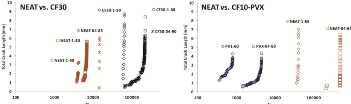
3.3 Crack growth
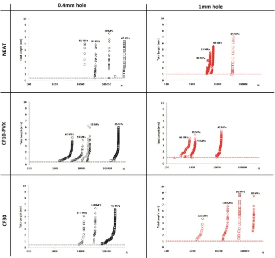
Crack growth was first considered by comparing the evolution of total crack length for the three materials under different testing conditions. The main results for each material are summarized in Fig.7, as a function of micro-hole diameter. It has to be remarked that it was not always possible to detect the presence of the crack immediately after it started. In a few cases the curves are thus incomplete in the initial region, although a significant portion of fatigue crack propagation curve could be observed. As a first observation it can be noticed that for all materials increasing the size of the micro-hole diameter resulted in a substantial change of crack propagation curves, with a shift towards shorter life times and faster propagation rates. A similar effect was also observed when increasing stress levels for a given
11
micro-hole size. In Fig. 8, a comparison of results for different materials for equal hole diameter and equal (or very similar) stress level is instead reported. By comparing neat PEEK and short fiber reinforced CF30 under the same testing condition, the beneficial effect of the reinforcing phase can be betterappreciated. The number of cycles to failure increased significantly and failure was more progressive, with presence of an extended region in which crack propagated more slowly, before entering the final propagation phase in which crack growth rate are instead comparable. On the other hand, when
comparing neat PEEK with CF10-PVX it is again apparent the detrimental effect of the inclusion of fiber and lubricating agent in the matrix. With maximum stress level of 60 MPa, CF10-PVX reached failure within a few hundreds of cycles, whereas at the same loading conditions fatigue life of neat PEEK is in the order of thousands or hundreds of thousands of cycles.
12
Fig. 8. Fatigue Crack Propagation curves for materials (same micro-holes, stress levels).For all materials, the presence of distinct phases for crack nucleation and propagation could usually be noticed, but with different behaviors in terms of total duration and presence of stable or fast propagation period. The beginning of the crack propagation phase was considered as corresponding to the cycle number at which a crack could be noticed at the edge of the micro-hole. This was identified for each test by means of the procedure described in paragraph 2.2. The average ratios between nucleation and total life time (RNuc/Tot) are summarized in Tab. 3, as a function of material and micro-hole diameter. For neat PEEK, the crack propagation phase always covered only a reduced portion of the total life. In general, the propagation was rather fast, as soon as the crack was detectable on the surface the specimen failed shortly after. Considering all tests, the average percentage value of time spent for nucleation was approximately 78.1%, with a slight increase when going from 0.4 to 1 mm micro-hole diameter. Overall, the results seem to indicate that the neat PEEK fatigue crack initiation was possibly more of the point-initiation type, with a crack propagation life usually short compared with the total life. For CF10-PVX, considering all tests, the average percentage value of time spent for nucleation was approximately 45.5%. It has to be remarked that for this material the time spent in the nucleation phase was indeed quite variable (i.e. range of values between 20% and 77% of total life).
RNuc/Tot (%) Average Crack Growth rate [m/cycle)
0.4 mm 1 mm Overall 0.4 mm 1 mm Overall
Neat 75.2% 82.8% 78.1% 0.83 1.6 1.02
CF10-PVX 43.3% 47.0% 45.5 0.205 2.20 1.44
CF30 51.6% 72.9% 63.7% 0.15 0.67 0.45
Tab. 3 Average nucleation/Total life ratios and crack growth rates
While such variation is possibly a consequence of the heterogeneous nature of the material, overall the average earlier onset of visible cracks, despite the lower stress levels, could be a further indication that fiber ends and particles may give rise to a negative action against crack initiation due to local stress
13
concentration effects. For CF30, the average ratio RNuc/Tot was 67.5%, although it has to be remarked that the number of specimens tested for which it was actually possible to clearly identify the start ofpropagation process was more limited. The average values of the ratio RNuc/Tot indicate that in comparison with CF10-PVX a longer time is spent in the nucleation phase, despite nearly double stress levels, whereas in comparison with neat PEEK the crack may nucleate earlier or in a comparable time. Tab. 3 also includes average crack growth rates during "stable crack propagation phase" (i.e. not considering the last loading cycles of the tests, when crack propagation abruptly increases before failure). Overall, the crack growth rate increased with the micro-hole diameter as well as with stress level, although the observed behavior changed significantly depending on material. Since the materials were tested within different stress ranges the comparison of these experimental observations is not straightforward, in particular in terms of absolute values. Anyway, taking as reference neat PEEK, it is possible to note that for CF30, despite higher applied maximum stress, average crack growth rate is lower, suggesting that fibers exert a positive action against crack propagation. On the other hand, CF10-PVX, exhibited a marked difference between 0.4 and 1 mm micro-hole diameter. This could possibly indicate the transition from a condition in which the size of the micro-hole has an effect comparable with that of inherent defects to a more critical loading condition in which the micro-hole is large enough to fully dictate the evolution of the fatigue process.
3.4. Fatigue crack propagation curves
By applying definitions given in equations (1) and (2), crack propagation rate dL/dN could be evaluated as a function of K as shown in Fig. 9. Based on these data, it is possible to evaluate the Paris' Law coefficients as summarized in Tab. 4, in which values were obtained by regression on the whole data available.
m C
Neat 6.8 1.05E-07
CF30 6.52 8.43E-09
CF10-PVX 6.67 2.06E-06 Tab.4 Paris' Law coefficients
Despite the scattered results, a significant trend in the C parameter can be noted, with a much lower value of this coefficient for CF30. Considering the exponential term m, values were instead quite similar. A few values for coefficient m can be found in literature for this class of material. As an example, in [17] a value of about 4 for neat PEEK and slightly lower for CFR PEEK is reported. In [10] Friedrich et al. reported a
14
higher range of values (i.e. from 8.9 for PEEK up to 13 for CFR/PEEK, R=0.22), whereas in [9] Saib et al. reported values in the 5.89-12.47 range for PEEK and its short fiber reinforced composites. In particular, for a CFR/PEEK with 30% wt a value of 6.37 was reported (R=0.1) whereas for neat PEEK a value of 7.2.Fig. 9. Fatigue crack growth rates.
4. Discussion
Considering the sensitivity of SFR composites to the presence of micro-notches, in [19] the existence of a correlation between cyclic creep and fatigue strength was observed on polyamide reinforced with short glass fibers. Due to the global nature of creep phenomena, it was inferred that this could be an indication
15
that a SFR composite could exhibit lower sensitivity to notches. SFR composites, contrary to unfilled polymers, are full of local notches due to the presence of the reinforcing phase. As a consequence, local variations (like scratches or notches) should have a lower influence on fatigue lifetime compared to the global effect of collective notches (fiber ends) present in the material that determines variations in lifetimes.An experimental comparison of the fatigue strength of plain and notched specimens of neat and short carbon fiber reinforced PEEK was reported in [17], showing that unfilled material was more sensitive to notches than reinforced material. In this study, fatigue crack propagations aspects for neat and SFR PEEK in the presence of notches were also considered. For neat PEEK, fatigue crack initiation was found to be of the point-initiation type, with a crack propagation life extremely short compared with the total life due to a very high crack propagation rate. Fatigue life was controlled by the behavior of a crack initiation and the material exhibited a high sensitivity to a notch. On the contrary for CFR PEEK, they found that fatigue crack initiated from near the fiber ends due to stress concentration effects, but crack growth rate was much less (up to two orders of magnitude in the case of CF30) than that in the neat matrix. They concluded that fiber reinforcement gave rise to negative action against crack initiation, since micro-fibers can act as preferential crack nucleation points, and positive action against crack propagation, since micro-fibers oppose crack propagation by dissipating energy in different ways (pull-out, fracture and
debonding). Considering the materials examined in this work, investigations were carried out in a
previous research regarding the presence of a correlation between cyclic creep and fatigue strength for the SFR PEEK under examination [7]. They revealed the presence of such correlation for C30 and to a slightly lesser extent for C10-PVX; for neat PEEK, it appeared to be less significant. Thus, it was concluded that SFR PEEK could be less sensitive to the presence of a notch but that sensitivity may be different depending on the composite systems considered and on notch size compared to some
characteristic dimensions of the reinforcing phase. Overall, the results obtained in the present study for CF30 and neat PEEK seem to confirm this type of behavior. For neat PEEK, most of the fatigue lifetime is spent for crack nucleation but, after crack initiation, propagation is very fast. For CF30, on the one hand, fibers act as “weak points” regarding nucleation, which is slightly anticipated, but they also act as obstacles to crack propagation, so that after crack initiation failure is more progressive. When comparing neat PEEK and CF10-PVX, a reverse effect can instead be noticed. In particular, this type of SFR composite exhibited lower fatigue strength and, in some cases, faster crack propagation. Although this behavior can be somewhat surprising, it is in line with previous observations on plain specimens [7] on
16
this specific material and could be considered a consequence of the material's highly heterogeneous nature. In this case the combination of lower fiber amount and the presence of fillers contribute to unbalance the negative and positive actions of the reinforcing phase previously described, reducing the efficacy of the reinforcing action of the fiber. Results for this material are particularly relevant, since the examined CF10-PVX can be considered as a possible example of "worst case scenario" in which negative interactions between filler, short fiber and matrix may result in a composite which is substantially weaker than the matrix itself.It should be remarked that the goal of present work was to compare materials commercially available for mechanical applications. Thus, it was not possible to investigate different combinations of fiber
concentration and additives (i.e. CF10 and/or CF30 both with and without additive particles). Of course, this would allow better appreciation of separate effects of each type of constituent. Similarly, the direct contribution of graphite on the fatigue performance and crack propagation could not be explicitly taken into account. Its significance was inferred mainly basing on the different behavior observed for CF10-PVX, compared to CF-30, at the macroscopical level. Interestingly, this was also supported by findings of our previous study on rolling contact fatigue for rollers made of the same material, in which we documented with microscopic analyses the presence of micro-cracks originating from the filler-matrix interface [20].
The interpretation of results in terms of Paris' law provided some interesting insights on material response, although some limitations on the possibility to compare results with different micro-notch size emerged. Results were rather scattered and while average values of exponential coefficients were similar between materials, single test values were more dispersed, although always well within the range of values reported in literature. Interestingly, a significant dispersion for crack-propagation data for CFR-PEEK composites was reported also in [10]. Nevertheless, it is worth noting that despite the use of a non-standard testing procedure, the values of the exponential coefficients are in line with previous findings, though in general it was not possible to establish a specific trend or correlation between exponential coefficient and reinforcement type.
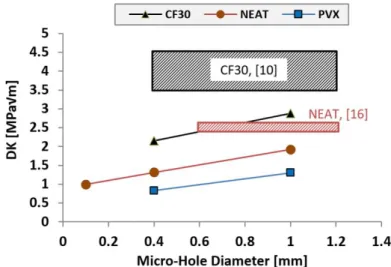
Finally, the identification of a threshold value for micro-notch dimension could be of particular interest for practical purposes. To this aim, a few additional tests were carried out on specimens with a micro-hole diameter of 0.1 mm. For PVX, three tests were run at 50, 55 and 60 MPa. In all cases, failure occurred after a number of cycles similar to tests on un-notched specimens at the same stress level. Even more noticeably, failure did not occur in the micro-notch area but cracks nucleated far from the hole region.
17
This may indicate that the influence of such a small notch is comparable to (actually lower than) that of material inherent defects. Test were also carried out on neat PEEK with a micro-hole diameter of 0.1 mm, but with higher maximum stress level (80 MPa - material fatigue strength for un-notched condition). The specimen reached 106 cycles without failure, again suggesting that the material is not sensitive to the presence of such a small notch. Although these few tests in presence of smaller micro-notches must be considered as a preliminary approach, they seem to confirm the existence of some critical notch sizes, below which the influence of a small notch is comparable with that of material inherent defects. In this respect, it is also interesting to note that based on results reported in Fig. 6, for each material it is possible to estimate the value Kinit for which 106 life cycles were completed. For 0.4 and 1 mm hole diameters respectively, these values are 2.15-2.88 MPa√m for CF30, 1.31-1.92 MPa√m for neat PEEK and 0.83-1.30 for CF10-PVX. At present, only a few studies reported threshold values Kth for PEEK and its SFR composites. As a reference in [21] for neat PEEK a value of approximately 2.5 MPa√m was determined, referring to a mode I long crack growth, whereas based on [10] a value of 3.5-4.5 MPa√m could be estimated for CF30. As shown in Fig. 10, the experimental results are slightly lower than these literature data, but do present a very similar order of magnitude.Fig. 10. Kinit - micro-hole diameter.
This point certainly deserves further investigation, by testing a higher number of specimens for each material and considering micro-notches having lower dimensions. An interesting future development could be to attempt a sort of transposition of the Murakami’s approach [22] proposed for metallic material also for these materials. The fatigue limit of SFR PEEK could be possibly regarded as the
non-18
propagation threshold of inherent or early formed micro-cracks generated by the mismatch between filler and matrix, having approximately the same size typical of the filler from which they originate.5. Conclusion
The effect of micro-notches on the fatigue behavior of neat and short carbon fiber reinforced PEEK was examined by testing specimens having blind micro-holes drilled on the surface. For all materials, the presence of a micro-notch resulted in a decrease of fatigue strength, compared to plain specimen, but with different sensitivity and crack propagation behaviors depending on reinforcement nature and notch size. For neat PEEK, most of the fatigue lifetime is spent for crack nucleation but, after crack initiation, propagation is very fast. When PEEK is reinforced with short fibers only and with higher fiber weight fraction (i.e. CF30), the fatigue properties are enhanced by the strengthening effect provided by the reinforcing phase. Fibers act as “weak points” regarding nucleation, which is slightly anticipated, but they also act as obstacles to crack propagation, so that after crack initiation failure is more progressive. In the presence of reduced fiber content and filler inclusion (i.e. CF10-PVX), a more heterogeneous material is created in which fatigue strength is instead lower and in some cases crack propagation faster.
The results in terms of Paris' law average values of exponential coefficients were similar between
materials and within the range of values reported in the literature, despite the use of a non-standard testing procedure. In general, it was not possible to establish a specific trend or correlation between exponential coefficient and reinforcement type. The existence was investigated of a critical notch size below which the influence of a small notch is comparable with that of material inherent defects. This could be of particular interest for practical purposes and preliminary investigations seem to confirm the presence of a threshold value for micro-notch dimension, although further testing is necessary.
Declaration of Interest
Conflict of interest: none. This research did not receive any specific grant from funding agencies in the public, commercial, or not-for-profit sectors.
Acknowledgements
19
References1. Berer M, Tscharnuter D, Pinter G. Dynamic mechanical response of polyetheretherketone (PEEK) exposed to cyclic loads in the high stress tensile regime. Int. J. Fatigue 2015;80:397-405.
2. Shrestha R, Simsiriwong J, Shamsaei N, Moser RD. Cyclic deformation and fatigue behavior of polyether ether ketone (PEEK). Int. J. Fatigue 2016;82:411-427.
3. Wang L, Shi S, Fu S, Chen G. Chen X. Evaluation of multiaxial fatigue life prediction criteria for PEEK. Theor. Appl. Fracture Mech. 2014;73:128-135.
4. Brillhart M., Botsis J., Fatigue fracture behavior of PEEK. J. Reinf. Plast. Comp. 1993;12:943-950. 5. Simsiriwong J, Shrestha R, Shamsaei N, Lugo M, Moser RD. Effect of microstructural inclusions on fatigue life of polyether ether ketone (PEEK). J. Mech. Behavior Biomed. Mater. 2015;51:388-397. 6. Berer M, Pinter G. Determination of crack growth kinetics in non-reinforced semi-crystalline thermoplastics using the linear elastic fracture mechanics (LEFM) approach. Polym. Test. 2013;32:870-879.
7. Avanzini A, Donzella G, Gallina D, Pandini S, Petrogalli C. Fatigue behavior and cyclic damage of peek short fiber reinforced composites. Compos. Part B Eng. 2013;45:397-406.
8. Saib KS, Isaac DH, Evans WJ. Effects of Processing Variables on Fatigue in Molded PEEK and Its Short Fiber Composites. Mater. Manuf. Proc. 1994;9(5):829–850.
9. Saib KS, Isaac DH, Evans WJ. The effect of short carbon fiber reinforcement on fatigue crack growth in PEEK. Compos. Part A 1996;27A:547–554.
10. Friedrich K, Walter R, Voss H, Karger-Kocsis J. Effect of short fiber reinforcement on the fatigue crack propagation and fracture of PEEK-matrix composites. Compos. 1986;17:205-216.
11. Mortazavian S, Fatemi A. Fatigue behavior and modeling of short fiber reinforced polymer composites: a literature review. Int. J. Fatigue 2015;70:297-321.
12. Sonsino CM, Moosbrugger E, Fatigue design of highly loaded short-glass-fibre reinforced polyamide parts in engine compartments, Int. J. Fatigue 2008;30:1279–1288
13. Belmonte E, De Monte M, Hoffmann CJ, Quaresimin M, Damage initiation and evolution in short fiber reinforced polyamide under fatigue loading: Influence of fiber volume fraction, Composites Part B, 2017;113: 331-341.
14. Belmonte E, De Monte M, Hoffmann CJ, Quaresimin M, Damage mechanisms in a short glass fiber reinforced polyamide under fatigue loading, Int. J. Fatigue 2017;94:145–157.
20
reinforced thermoplastics, Int. J. Fatigue 2017;98:176-186.16. Sobieraj MC, Murphy JE, Brinkman JG, Kurtz SM, Rimnac CM. Notched fatigue behavior of PEEK. Biomater. 2010;31(35):9156-9162.
17. Nisitani H, Noguchi H, Kim Y-H. Evaluation of fatigue strength of plain and notched specimens of short carbon-fiber reinforced polyetheretherketone in comparison with polyetheretherketone. Eng. Fracture Mech. 1992;43:685-705.
18. Newman JC Raju IS. Stress-intensity factor equations for cracks in three-dimensional finite bodies subjected to tension and bending loads. NASA Technical Memorandum 85793, 1984.
19. Horst JJ, Spoormaker JL. Fatigue fracture mechanisms and fractography of short-glassfiber-reinforced polyamide 6. J. Mater. Sci. 1997,32:3641-3651.
20. Avanzini A., Donzella G., Mazzù A., Petrogalli C., Wear and rolling contact fatigue of PEEK and PEEK composites, Tribology International, 2013,57:22-30
21. Saib KS, Evans WJ, Isaac DH. The role of microstructure during fatigue crack growth in poly(aryl ether ether ketone)(PEEK). Polymer 1993;34(15):3199-3203.
22. Murakami Y, Metal fatigue: Effects of small defects and nonmetallic inclusions, Elsevier, Oxford, 2003.