AND SOUTHERN LAZIO
Ph.D. in Methods, models and technologies for
engineering
XXXII Cycle
Ph.D. thesis
About the impact of individual metering on the
energy efficiency of residential buildings
Supervisor
Prof. Marco Dell’Isola
Prof. Giorgio Ficco
Ph.D. student
Co-supervisor
Laura Canale
Prof. Domen Hudoklin
Coordinator
Prof.ssa Wilma POLINI
A te,
Per avermi sempre supportato.
This work represents the end of a meaningful professional and human experience, result of a research project that would not have materialised without the intellectual input and the support of great thinkers. Many people dedicated me their time for review and discussion and provided me with indispensable help and support for the realization of this thesis. To all those, I express my greatest gratitude.
I would like to thank my supervisors, for believing in my possibilities, for guiding me along this journey and for all the moments of useful and sincere discussion we had along this path.
Professor Marco Dell’Isola contributed with his intuitions and passionate interest for energy science and technology, which were a truly inspiration for me, and always ensured a smooth cooperation with all the parties involved.
Professor Giorgio Ficco provided me with his persistent help and with his useful teachings, I thank him for supporting me in all my research activities, as well as for the significant guidance provided.
Both of them provided me with substantial support for the publication of this thesis and of numerous research articles, which they read and reviewed with much-appreciated criticism. Their attention to detail helped me in developing my research skills. I could hardly imagine a better tuned research team.
I am also grateful to my co-supervisor Professor Domen Hudoklin, for dedicating time in reviewing my thesis.
Thank also to all the smart people I worked closely with, with particular reference to the researchers of the Unità Tecnica Efficienza Energetica of the ENEA Casaccia Research Centre, Biagio Di Pietra, Giovanni Puglisi and Ilaria Bertini for giving me their time, useful data and suggestions for the analysis performed within this thesis.
Finally, I would like to acknowledge with gratitude, the support and the love of my partner, my parents and my entire family, who all kept me going through this journey.
I
Since 2002, the European Union has promoted individual metering of energy consumption as an effective tool to improve energy efficiency in buildings.
In 2012, the Energy Efficiency Directive has set mandatory the individual heat accounting in buildings when centralized heating/cooling systems are installed, when technically feasible and cost efficient. As far, Member States of European Union adopted different approaches regarding this obligation, due to differences in their climatic conditions, building stocks characteristics and installed technologies but also to a lack of knowledge about the real impact of the use of such devices.
As a consequence, this measure has led to a series of technical, legal and consumer protection issues which still need to be solved.
This thesis aims to address, with a multi-thematic approach, the issue of measuring thermal energy consumption in residential buildings. A number of four research questions have been investigated in order to answer to the main question: “What is the
impact of the use of energy metering devices in residential buildings?”.
To this aim, a number of six case studies were investigated to: i) evaluate the expected metrological performances of individual metering devices on-field; ii) assess the potential energy saving gainable through the use of individual metering devices in Mediterranean climates and analyse possible feedback strategies to enhance end-user awareness; iii) evaluate the potential impact of different energy policies on the outcome of this energy measure; iv) evaluate the performances of current methodologies applied for end-users’ profiling through individual metering.
Results of this thesis provide useful insights to researchers, designers and policy makers, filling some of the gaps highlighted in the existing scientific literature in all the analysed areas.
II
TABLE OF CONTENTS
ABSTRACT ... I List of Figures ... IV List of Tables ... VII
INTRODUCTION ... 1
CHAPTER 1. Individual Heat Metering Devices ... 10
1.1 Measuring systems for heat accounting ... 10
1.1.1 Direct Heat Meters ... 13
1.1.2 Metrological issues of DHMs ... 16
1.1.3 Insertion time counters ... 21
1.2 Metrological issues for distributed IHASs ... 23
1.3 Case study #1: An uncertainty model for IHASs reliability ... 29
1.3.1 Methodology ... 29
1.3.2 Validation of the uncertainty model and case studies ... 34
40 CHAPTER 2. Energy Saving from Individual Metering ... 41
2.1 Energy saving from heat metering and accounting ... 41
2.2 End-user feedback to increase energy-awareness in smart-homes ... 45
2.3 Case study #2: Experimental campaign to assess energy saving from IHASs ... 47
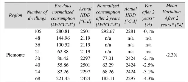
2.3.1 Methodology ... 47
2.3.2 Results and discussions ... 49
2.4 Case study #3: Design and application of a novel feedback strategy about energy consumption ... 56
2.4.1 Methodology ... 56
2.4.2 Results and discussions ... 60
CHAPTER 3. Policies for Individual Metering ... 67
3.1 Allocation rules in Europe ... 68
3.2 Cost-benefit analysis of individual heat metering and accounting systems ... 76
3.3 Modelling energy consumption of building-stock to project policy scenarios .. 80
3.4 Case study #4: A new heat cost allocation method for social housing ... 83
3.4.1 Methodology ... 83
III
3.5 Case study #5: Estimating the impact of heat accounting on Italian residential
building stock ... 94
3.5.1 Methodology ... 94
3.5.2 Results and discussions ... 100
CHAPTER 4. Forecasting Consumption in Energy Networks ... 103
4.1 Overview on Natural Gas Networks rules and regulations ... 103
4.2 Profiling energy consumption in Natural Gas Networks ... 106
4.3 Case study #6: Standard Load Profiles for Natural Gas consumption simulation at urban scale ... 117
4.3.1 Materials and methods ... 117
4.3.2 Results and discussions ... 120
CONCLUSIONS ... 127
IV
L
IST OF
F
IGURES
Figure 1.1 – DHMs constructive scheme ... 14
Figure 1.2 – Electronic HCA constructive scheme ... 18
Figure 1.3 - HCA operative scheme ... 24
Figure 1.4 – Flow chart of the developed model... 29
Figure 1.5 - Heat share uncertainties trend as a function of the correlation coefficient rb and of the number of apartments, assuming 𝑛𝑟𝑎𝑑𝑎𝑝 = 6: a) Similar radiators and installations (𝑟𝑟𝑎𝑑𝑏= 0.90), critical condition; b) Different radiators and installations (𝑟𝑟𝑎𝑑𝑏= 0.10), critical condition; c) Similar radiators and installations (𝑟𝑟𝑎𝑑𝑏= 0.90), optimal condition; d) Different radiators and installations (𝑟𝑟𝑎𝑑𝑏= 0.10), optimal condition... 33
Figure 1.6 – Heating plant scheme of the two-family house ... 34
Figure 1.7– Building #2: Heating plant installation scheme ... 36
Figure 1.8 - Case study #3: Heating plant installation scheme ... 38
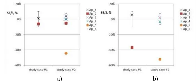
Figure 1.9 – Experimental relative share error and expanded uncertainty of the investigated buildings: a) HCAs, b) ITCs. ... 40
Figure 2.1 – Existing scientific literature regarding individual metering systems’ energy saving, (°) papers reviewed in [25]; (*) papers reviewed in [24] ... 44
Figure 2.2 - Regional share of dwellings supplied by CHS (source: ISTAT). ... 48
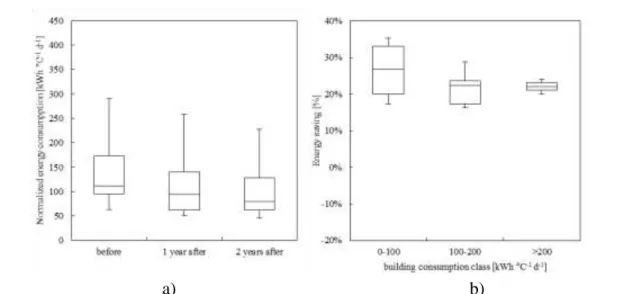
Figure 2.3 - Energy consumptions of the investigated buildings before and after the installation of the sole HAT systems: a) Normalized energy consumption, b) Energy saving. ... 51
Figure 2.4 – Regression analysis of investigated buildings in terms of energy consumption before and after the installation of the sole HAT systems: a) Specific energy consumption, b) Energy saving. ... 53
Figure 2.5 - Energy consumption of investigated buildings before and after HAT systems installation with boiler replacement: a) Normalized energy consumptions, b) Energy saving... 55
Figure 2.6 – Regression analysis of investigated buildings in terms of specific energy consumption before the installation of HAT systems performed together with the replacement of the boiler: a) specific energy consumption after the installation, b) energy saving after the installation. ... 55
V
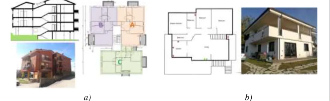
Figure 2.8 – a) Heating plant case study building, b) Electrical Plant case study building with location of devices (red dots: smart-plugs, green dots: current clump meters).
... 57
Figure 2.9 – Results of surveys analysis ... 60
Figure 2.10– Direct feedback: a) Heating Plant, b) Electrical Plant ... 62
Figure 2.11 - Indirect feedback ... 63
Figure 2.12 – Data usage for main appliances (ISTAT, 2014) ... 65
Figure 3.1 – Fixed and variable share of heating and cooling energy cost ... 68
Figure 3.2 - Range for variable share of heat cost allocation in some EU Member States ... 70
Figure 3.3 – Population unable to keep home adequately warm by poverty status (% of population, year 2018, exceptions: CZ, AT, LU, SE, LT, SK, RO, TR, MT, PL, RS, MK, ES, IE (2017), CH, IS (2016)) ... 75
Figure 3.4– Total one-off and running costs of DHMs and HCAs installation per dwelling 78 Figure 3.5 – UBEMs classification overview [160] ... 81
Figure 3.6 – The investigated building ... 87
Figure 3.7 - Layout schemes of the building (basement and typical floor) ... 87
Figure 3.8 - Cross section of the investigated building ... 87
Figure 3.9 - Individual consumptions trend: a) a typical month, b) the whole heating season ... 89
Figure 3.10 - Comparison between different cost allocation methods in the investigated social housing building... 93
Figure 3.11 – Flow chart of the developed model... 95
Figure 3.12 - Number of dwellings per region and per building type. ... 96
Figure 3.13 – Graphical representation of the BTM for a given climatic zone. ... 98
Figure 3.14 – Results of the economic feasibility analysis making efficient the installation of HAT in different incentive scenarios: a) EPH,min as a function of the number of dwellings; b) PBT as a function of EPH. ... 101
Figure 4.1 –NG regulation evolution in Europe ... 104
Figure 4.2 – Qualitative representation of sigmoid SLPs ... 113
Figure 4.3 – German classification of end users ... 114
Figure 4.4 – Qualitative representation of UK SLPs ... 116
Figure 4.5 - The analysed building stock ... 117
Figure 4.6 - Overview on the methodology applied to determine the error of the analysed methods ... 119
Figure 4.7 – Monthly relative error of the analysed methods applied to an urban scale... 120
Figure 4.8 – Monthly consumption and relative error of the analysed methods ... 121
Figure 4.9 –Mean monthly standard deviation of the methods in each scenario, year 2017 123 Figure 4.10 –Year error of the methods in each scenario, year 2017... 123
VI
Figure 4.12 – Monthly error of the analysed method applied to a neighbourhood scale ... 124 Figure 4.13 – Comparison between the real and estimated consumption of the neighbourhood under the defined scenarios ... 126
VII
L
IST OF
T
ABLES
Table 1.1 - accounting systems feasibility in space heating and cooling plants. ... 13
Table 1.2 – Reference standard for DHMs ... 14
Table 1.3 – Maximum Permitted Errors for DHMs ... 16
Table 1.4 – Scientific literature about DHMs on-field characterization ... 17
Table 1.5 - Technical characteristics of HCAs ... 20
Table 1.6 - Installation influence factors affecting heat output of installed radiators ... 26
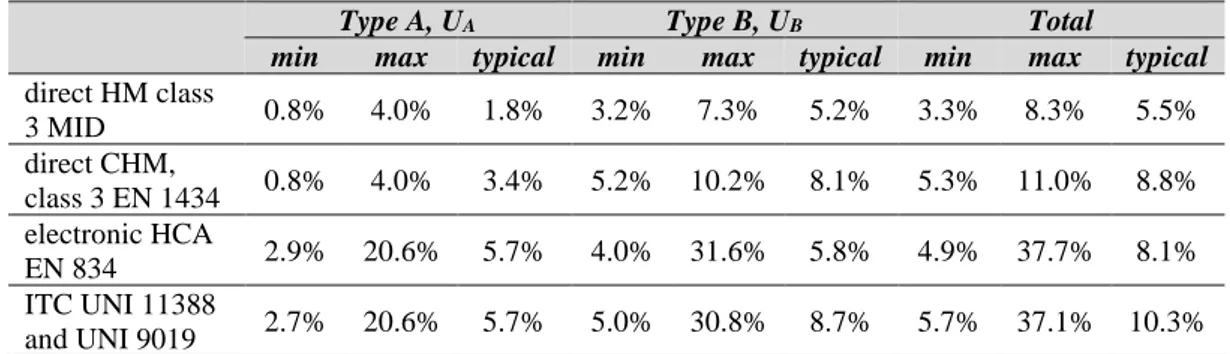
Table 1.8 – Expanded uncertainties of single heat metering and accounting devices ... 27
Table 1.9 - Weighting factors for the estimation of correlation factors ... 31
Table 1.10 - Expanded uncertainty of IHASs as a function of 𝑟𝑟𝑎𝑑𝑎𝑝, 𝑟𝑟𝑎𝑑𝑏 and 𝑟𝑏 ... 33
Table 1.11 – Building #1: Uncertainty budget for a single device (HCA) ... 35
Table 1.12 – Building #1: Uncertainty budget for a single device (ITC) ... 35
Table 1.13 – Building # 2: Uncertainty budget for a single device (HCA) ... 37
Table 1.14 – Building # 2: Uncertainty budget for a single device (ITC) ... 37
Table 1.15 – Building #3: Uncertainty budget for single device (HCA) ... 39
Table 1.16 – Building #3: Uncertainty Heat budget for single device (ITC) ... 39
Table 2.1 - Italian dwellings classified by heating plant (source: ISTAT). ... 47
Table 2.2 - Characteristics of the investigated buildings sample. ... 48
Table 2.3 – Energy consumption variation due the sole installation of HAT systems, 1-year post installation ... 50
Table 2.4 – Energy consumption variation due the sole installation of HAT systems, 2-years post installation (data available only for Piemonte region) ... 51
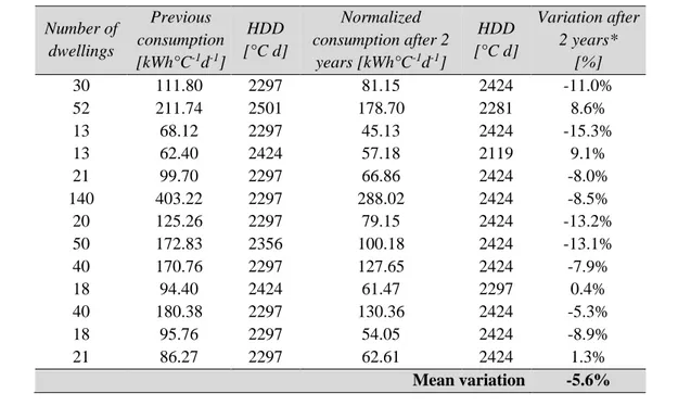
Table 2.5 – Energy consumption in buildings where HAT systems were installed together with boiler replacement, variation after 1 year ... 54
Table 2.6 – Energy consumption in buildings where HAT systems were installed together with boiler replacement, variation after 2 years ... 54
Table 2.7 – Feedback characteristics ... 59
Table 2.8 - Characteristics of the direct and indirect feedback ... 61
Table 2.9 – Variation of energy consumption indexes in building #1 calculated before and after the information campaign ... 64
Table 2.10 – Variation of energy consumption indexes in building #2 calculated before and after the information campaign ... 64
VIII
Table 2.12 – Calculated energy consumption of appliances (ISTAT, 2014) ... 66
Table 3.1 – Heating costs allocation rules in Europe [27] ... 69
Table 3.2 – Advantages and disadvantages of different compensation strategies ... 73
Table 3.3 – Ranges of CFs in different countries. ... 73
Table 3.4- Compensation factors in EU MSs ... 74
Table 3.5 - Total running and capital costs of individual heat metering and accounting systems in EU ... 77
Table 3.6 - Overview of the relevant literature regarding cost-benefit analysis of individual metering and temperature control systems at national scale... 79
Table 3.7 – Advantages and disadvantages of UBEMs [160] ... 81
Table 3.8 – Calculation and accounting scheme of Extra-Consumptions ... 85
Table 3.9 – Thermal and Physical Characteristics of the investigated building ... 88
Table 3.10 - Energy costs for space heating for the whole heating season 2016-2017 ... 89
Table 3.11 - Voluntary and involuntary extra-consumptions according to the proposed method ... 90
Table 3.12 – Fixed Proportionality principle: Heat costs share 2016-2017 in the investigated building ... 90
Table 3.13 - Responsibility principle: Heat cost share 2016-2017 in the investigated building ... 91
Table 3.14 - Fairness principle: Heat cost share 2016-2017 in the investigated building .... 92
Table 3.15 - The proposed method: Heat cost share 2016-2017 in the investigated building ... 92
Table 3.16 - Italian dwellings occupied by residents classified by category and construction age... 96
Table 3.17- Comparison between energy consumption for space heating estimated by the developed model and REBs/NEBs in 2015 [49, 50]. ... 100
Table 3.18 –Energy savings achievable through different fiscal policies and obligation approach [Mtoe]. ... 102
Table 4.3 –End-use categories of the analysed sample ... 109
Table 4.2 – End-use categories ... 110
Table 4.3 – Withdrawal classes ... 110
Table 4.4 – End User Categories of English NG customers ... 115
Table 4.5 –Errors of the analysed methods for: Heating Season (HS), non-Heating Season (nHS), year 2017 ... 120
Table 4.5 – Measured and estimated energy consumption with relative seasonal errors, year 2017 ... 125
IX
Abbreviations and acronyms
AEEGSI Italian Regulatory Authority for Electricity Gas and Water AiCARR Italian Association for Air Conditioning, Heating and Cooling
AR Asset Rating
AU Allocation Unit
BTM Building Typology Matrix CA Construction Age
CFs Compensation Factors CF Correction factor
CHS Centralized Heating Systems
CV Customer Value
DHMs Direct Heat Meters
DM Daily-Metered
EED Energy Efficiency Directive
ENEA Italian Agency for New Technologies, Energy and Sustainable Economic Development
ESCO Energy Service Company
EU European Union
HAT Heat Accounting and Thermoregulation HCA Heat Cost Allocator
HDD Heating Degree Days
IGC Industrial Natural Gas Consumption
HE Heating Element
IHASs Indirect Heat Accounting Systems ISTAT Italian National Institute of Statistics
ITC-DDC Insertion Time Counters Compensated with heating Degree Days
ITC-TC Insertion Time Counters Compensated with average Temperature of heat transfer fluid
MID Measuring Instruments Directive
MSs Member States MULTI_FAM Multi-family NG Natural Gas NGN Natural Ga Network NDM Non-Daily Metered OR Operational Rating REBs Regional Energy Balances
RGC Real natural Gas Consumption of Residential customers SIN_FAM Single-family
SLP Standard Load Profile
TGC Total natural Gas Consumption of the network TRVs Thermostatic Radiator Valves
X
Symbols
𝑐̅𝑝 average specific heat capacity of the heating thermal fluid
e error
𝑄̇𝐻𝐸 nominal heat power of the heating element 𝑇𝑎,𝑐 reference values for the ambient temperature 𝑇𝑎,𝑖 ambient temperature
𝑇𝑒,𝑐 reference value for the heating fluid temperature 𝑇𝑚,𝑐 reference value for the heating fluid temperature 𝑇𝑚,𝑖,𝑐 average temperature of the heating fluid during 𝜗𝐶𝑉
𝑇𝑚,𝑖 average temperature of the heating fluid during 𝜗𝑂𝑉 𝜗𝐶𝑉 closing time of the valve
𝜗𝑂𝑉 opening time of the valve
E Primary energy need [kWh m-2 year -1]
h Inter-storey height [m]
K coefficient of proportionality between the allocation unit and the actual heat used
KC rating factor for thermal contact between heat cost allocator and the
heating element
KQ rating factor for thermal output of the heating element
KT rating factor for indoor temperature
n characteristic exponent of the heating element
q volumetric flow rate ΔT temperature difference 𝜂 System efficiency [-] ρ flow density τ time constant 𝑈 Thermal transmittance [W m-2 K-1] Other subscripts AC Annual Consumption DC Daily Consumption d distribution f floor gen generation H heating min minimum P primary r roof r regulation wall walls win windows
1
INTRODUCTION
Achieving energy efficiency in both existing and new buildings has become increasingly important within the last decades, as buildings are responsible for 36% of global final energy consumption and nearly 40% of total direct and indirect CO2 emissions [1]. Greenhouse Gas (GHG) emissions related to growing building energy use has been the cause of a severe environmental impact, leading governments to approve a number of protocols to reduce energy consumption from fossil fuels and promote energy efficient technologies and renewable energy use [2], especially in the buildings sector. In 2016, 75% and 60% of the countries had specific policies for, respectively, the implementation of energy efficiency strategies and for boosting the spread of renewable energy sources [3, 4]. Indeed, targeted policy actions on multiple fronts are therefore not only necessary, but indispensable for the mitigation of our energy and environmental impact. On the other hand, the vast majority of countries have not yet begun to face the energy transition process.
EU itself issued a series of directives, together with technical regulations, which are aimed at giving rules to reduce energy consumption of buildings in the direction of: i) increasing the energy performances of both buildings’ envelopes and installed technologies; ii) raising users’ concern about energy consumption and engage in correct energy management and, iii) making buildings’ energy consumption measurable and tangible to people through smart technologies.
Within this framework, the measure of energy consumed in individual dwellings certainly has represented a very debated topic in the last recent years, given its potential to become a relatively low-cost tool to reduce energy consumption in buildings.
In Europe, the very first attempt to regulate the installation of heat accounting and temperature control systems in individual dwellings is indirectly contained in Directive 93/76/CEE (SAVE) [5] to limit carbon dioxide emissions by improving
2
energy efficiency (through implementation of billing of heating, air-conditioning and hot water costs on the basis of actual consumption) and subsequently by Directives 2002/91/EU [6] and 2010/31/UE [7]. Indeed, these directives stated that the billing of heating, air conditioning and domestic hot water production based on individual consumption contributes to energy savings in the residential sector.
In this regard, in 2012 the Energy Efficiency Directive (EED) [8] imposed Member States (MSs) the obligation to install individual heat metering systems in buildings supplied by a centralized source of heating/cooling/hot water production provided its economic and technical feasibility and encouraged MSs to adopt transparent rules on consumption-based and informative billing. In fact, the installation of metering and sub-metering systems of energy consumption in the building sector is expected to increase end-user awareness, thus obtaining behavioural changes towards a greater energy efficiency. This is also emphasized in the newly amendment of the EED, in which it is explicitly stated that “Member States should take into account the fact that
the successful implementation of new technologies for measuring energy consumption requires enhanced investment in education and skills for both users and energy suppliers” [9].
Results from several scientific papers and research projects stand behind such policy: it is nowadays clear that the only interventions to improve the efficiency of energy plants and structures of the buildings are not enough to guarantee a reduced energy consumption. These must be combined with actions aimed at increasing the awareness and participation of the final customer, also through more frequent and detailed information on energy consumption [10].
It has been demonstrated that, in absence of periodic information, houses with identical energy performance and thermo-physical characteristics, even those designed for N-ZEB energy standards, can consume up to twice as much as each other, depending on the behaviour of the inhabitants [11]. Thus, inducing energy-efficient behaviour among tenants should represent a complement to other actions directly aimed at improving energy efficiency at building level, such as lowering the thermal transmittance of the building envelope or updating the central heating system with more energy-efficient devices [12].
3
However, this obligation has led to several technical, legislative and consumer protection implications, which to date are still open topics. In fact, the potential savings achievable through this measure are strongly related to the thermophysical characteristics of the building stock and of installed heating systems, to the climatic conditions, to the diffusion of these devices in certain markets and to cultural and economic aspects, playing a crucial role on the real success of energy retrofit interventions. Thus, the potential for energy saving of heat accounting is related to both the technical characteristics of the system and to the behavioural component whose weight on overall savings are not easily predictable. This results in a total energy saving still unquantifiable due also to the wide variability of installation and operating costs of metering and sub-metering devices in different EU countries.
Overall, quantifying the potential for energy savings is a difficult task, because energy is largely an "invisible" good [13-15]. This can make it difficult for users to have a clear idea of how its use varies over time and how this relates to significant benchmarks. Hence, it is also crucial to correctly design the way in which the information gatherable from individual metering and sub-metering devices arrives to final user.
Different transpositions have been adopted within EU MSs, with some MSs setting mandatory individual metering for space heating for almost all buildings and others exempting all the building stock [16-18]. Regardless of EED requirement about individual metering is subject to technical feasibility and cost-effectiveness [19, 20], current legislation within MSs lacks official indications about reference energy saving and standard costs. Nevertheless, some efforts have been made (or are in the testing/drafting phase), as for example in Italy, United Kingdom and Spain [21-23] to give tools and/or guidance about how to perform the economic feasibility analysis of individual heat metering and accounting systems. Furthermore, it is not specified if the cost-benefit analysis has to be performed at standard rating condition of the building rather than at operational ones. This leads professionals to manage very wide margins of exemption or obligation for the installation of heat accounting systems in buildings.
Several studies conducted in central EU countries demonstrated potential benefits variable between 8% and 40% [24-26]. Besides, standard figures of cost related to the
4
installation of individual metering systems are available only for few markets [16, 17, 27, 28]. As a matter of fact, it has been demonstrated that payback times vary between 3 and 16 years when the building energy need ranges from 300 to 100 kWh m-2 year-1 with an expected benefit of 25% [27].
From a policy and regulatory point of view, the introduction of transparent allocation rules for heating/cooling/hot water costs ensuring at the same time the transparency and accuracy of the individual energy metering is a difficult subject. Heat costs in multi-apartment buildings supplied by centralized energy sources can be divided into variable (i.e. the consumption of the user according to his need) and fixed (i.e. the consumption to run the system including heating of common areas and costs for ancillary devices).
As a matter of principle, variable costs should correspond only to “voluntary” consumption of single apartments, while fixed ones to all other costs that occur also when all users close their radiators. In this way, unoccupied dwelling would not permanently undergone a forced charge for unsolicited energy costs. On the other hand, two issues such as the so-called "heat thefts" [29] and "split incentives" in the energy retrofit of buildings, make the above-mentioned principle critical. In residential buildings, split incentives signify a misalignment between the landlord who pays the energy retrofit intervention and tenants who pay for energy consumption, thus resulting the direct beneficiary of the intervention itself [30]. Therefore, setting a high share of voluntary energy consumption could lead to the situation in which only tenants with the more unfavourable location within the building would benefit from a retrofit intervention, while all tenants would pay for it. For this reason, in many EU MSs specific compensation factors have been introduced, or methods to partially compensate for the greater heat losses occurring in some apartments, setting the use of compensation factors as mandatory, whereas in others compensation is forbidden by law. On the other hand, a low share of voluntary energy consumption may cause energy-inefficient behaviours even if this could lower the problem of energy poverty in particularly disadvantaged buildings, meaning that best-practices in heat cost allocation are subordinated to the in-depth knowledge of both the characteristics of the buildings and the cultural and economic conditions of tenants.
5
On the technical hand, two different categories of heat accounting systems are available on the market: Direct Heat Meters (DHMs) and Indirect Heat Accounting Systems (IHASs). EED sets as a priority of the installation of DHMs when economically and technically feasible; alternatively, the installation of IAHSs (e.g. Heat Cost Allocators, HCA, or Insertion Time Counters, ITC) is permitted. Unfortunately, due to heating plant configuration and to technical and architectural constraints, DHMs installation is often not feasible, while IHASs installation is almost always technically feasible in existing buildings with conventional radiators [31, 32]. However, the use of IHASs implies some issues in terms of consumer protection. In fact, accuracy of IHASs could range from 3.0% to 12.4% [33] and up to 30% [34] while in different operating conditions it ranges from about 2.7 % to about 11.7 % [35]. Moreover, only DHMs are currently regulated by legal metrology [36], therefore they can be used both for measuring thermal energy at the point of supply and also for sub-metering of energy consumption within the building. Finally, IHASs are lacking from a regulatory point of view and in most MSs, DHMs are also subject to on-field verifications, while IHASs have no legal verification constraints of the on-field performances.
Metering and sub-metering devices are fundamental also in management of energy networks, such as district heating or cooling, or natural gas networks, where they play a key role in the consumption billing and in the allocation of energy consumption between the different actors of the network. Forecasting energy consumption through periodical meter-readings can guarantee that the energy network operates in balanced conditions, which not only has important economic implications, but above all determines whether the network operates safely and ensures the continuity of supply.
In the above described context, it is clear how individual metering of energy consumption is a subject of multi-disciplinary nature which involves metrology, policy, energy management together with social and behavioural aspects which will be all analysed within the framework of the present research.
6
Aim of the work and research questions
The present research aims to address some of the gaps in the current scientific literature concerning the subject of energy metering which have been described in the above introductory section. The different topics have been approached from different perspectives. For this reason, the chapters of the thesis have been compiled in a thematic way and consistently with the candidate's research experiences. Specifically, this research will try to answer with an integrated approach to the following main research question:
What is the impact of the use of energy metering devices in residential buildings?
The initial idea of the research was to evaluate the impact of individual energy metering and sub-metering systems with two different viewpoints. The first, purely technical, aimed at evaluating the main metrological issues related to the installation of individual metering devices in single buildings. The second, more focused on energy efficiency, aimed at assessing the potential impact of the installation of such devices in residential buildings in terms of energy consumption reduction at large-scale.
However, further research questions have arisen from the first analysis: after performing an experimental campaign aimed at assessing the mean statistical energy saving achievable through the installation of these devices, it has been clear that a simple figure could not explain the complexity behind the high variability of the benefit potentially obtainable through these devices. This also meant that, to have an in-depth understanding about the energy saving induced by using metering devices, it would have been necessary analysing the way in which these are perceived and actually used inside single dwellings and how their potential could have been increased by acting on end-user understanding and behaviour.
Nevertheless, there are several ways in which one could act to achieve the goal to enhance the potential for energy saving of these devices: from this point of view, the level of user education and involvement with such devices is not the sole weighting component, but the definition of appropriate energy policies on both micro- (i.e. single
7
building level) and macro- (i.e. building stocks level) scales is also of fundamental importance.
Lastly, an investigation of the methodologies employed to profile end-user’s energy consumption within energy networks has been performed aimed at evaluating the impact of correct individual metering and sub-metering at a building and district levels in the management and regulation of energy networks.
The research questions arising from the main question and sub-questions are described in the following:
A. What are the expected on-field metrological performances of distributed
individual metering and sub-metering systems with respect to consumer protection?
B. What is the potentially achievable energy saving through the installation
of individual metering devices?
b1 – What is the statistical impact of individual metering devices in
Mediterranean climate?
b2 – In which way it is possible to act on final users in order to enhance
their engagement and to raise their awareness about energy consumption?
C. Is it possible to guide the success of the action about individual metering
in residential buildings at a political/regulatory level?
c1 – What are the best practices in allocation of energy costs at a building
level?
c2 – What is the impact of individual heat metering and accounting in
different policy scenarios at a Country-scale level?
D. What is the impact of metering devices in management and regulation of
energy networks?
In the following, an overview about the research outline together with the thesis structure will be given in order to allow a clear understanding during the reading of the present work.
8
Research outline and thesis structure
The thesis is organized in four main thematic chapters, each containing an introductory section in which the scientific relevance of the research topic and the gaps in current scientific literature are highlighted.
Every chapter aims to address one of the main research questions by analysing one or more case studies each, in turn, answering one of the sub-research questions.
Chapter 1 addresses the problem of thermal energy measurement in terms of
on-field reliability of indirect heat accounting systems in residential buildings. An overview about the technical and regulatory state of the art about thermal energy metering and accounting is provided and the analysis of a case study (case study #1) is provided in which a novel model for the estimation of heat accounting systems reliability is described and proposed.
Chapter 2 is dedicated at estimating the potential energy saving achievable through
the installation of individual thermal energy metering and accounting and temperature control devices in residential buildings. The issue is addressed on two different scales. In case study #2, the author intends to determine the average statistical benefit obtained by installing the aforementioned devices in a sample of 3000 apartments in Italy, addressing the problem with a macro-scale approach. By analysing the case study #3, on the other hand, the author focuses on the main factors influencing end-user awareness, investigating possible strategies for optimizing user communication through the use of modern technologies made available by the Internet of Things, with a micro-scale approach (i.e. at a single building level).
In Chapter 3 the topic is addressed with a policy-making perspective. A discussion is provided about the main issues related to: i) the current heat cost allocation rules within Europe, ii) the technical-economic feasibility constraints of the installation of individual metering devices and iii) the modelling of the energy consumption of building stocks for the projection of different policy scenarios. Viable energy policies are evaluated on both the micro- and macro-scales with particular focus on optimizing the heat cost allocation rules at a building-scale level (case study #4) and evaluating
9
the impact of different policies to the whole potentially achievable energy saving at a Country-scale (case study #5).
Finally, Chapter 4, is aimed at evaluating the impact of correct individual metering and sub-metering at a building and district level in the management and regulation of energy networks, with particular focus on natural gas networks, which are more widespread on the Italian territory than the district heating/cooling ones (making it easier to find large-scale data for modelling purposes). In particular, in case study #6, the methodologies employed to profile end-user’s energy consumption within energy networks have been evaluated in terms of performances in predicting final energy consumption of residential users.
In Table 0.1, an overview on the thesis structure is provided together with some additional useful information.
Table 0.1 – Thesis structure and outline
RQ
Topic Case study
Analysis
Chapter
main sub scale type
A Metrology #1 single building modelling/experimental 1
B b1 Energy
Efficiency
#2 building stock experimental
2
B b2 #3 single building experimental
C c1 Energy
Policy
#4 single building modelling
3
C c2 #5 building stock modelling
10
CHAPTER 1.
I
NDIVIDUAL
H
EAT
M
ETERING
D
EVICES
In this Chapter, after the analysis about technical and legal metrology features of direct and indirect heat accounting devices, a statistical model for the estimation of the uncertainty of heat accounting through indirect methods is proposed as case-study. The developed model has been applied to three different typical buildings: i) a two-family house, ii) a small building, iii) a large multiple building. The developed model has been proposed by Italian Association for Air Conditioning Heating and Refrigeration (AICARR) as reference method for heat accounting uncertainty estimation in the new version of the national standard UNI 10200 [37].
1.1 Measuring systems for heat accounting
As stated above, heat metering and sub-metering systems are normally classified as "direct" and "indirect". Thermal energy meters provide a “direct” accurate measurement of thermal energy supplied in a heat circuit and they are regulated by legal metrology [36] and detailed harmonized technical standards [38-46]. On the other hand, IHASs are based on the estimation of thermal energy emitted by single radiators/convectors or in certain thermoregulated zones of the heating/cooling plant. Nowadays, in the European market, electronic HCAs are the most common indirect accounting systems. HCAs allow an “indirect” measurement of thermal energy, since they measure some parameters correlated to it, as described in corresponding EN 834 [47] and EN 835 [48] technical standards. For the sake of completeness, besides HCAs, in the Italian market other indirect accounting devices are quite common. Such
11
systems are based on the registration of the opening periods of a single thermal zone (i.e. a portion or the entire building unit) or of the valve of a single radiator. The opening periods of each valve are then compensated with the average temperature of the heat transfer fluid or with the actual degree days (i.e. the difference between the conventional ambient temperature and external one), according to [49] or [50] national standards, respectively. Besides, Compact direct Heat Meters (CHMs) applicable to single radiator/convector have been recently developed [51] and they are currently under type approval tests according to the Measuring Instruments Directive (MID) [36] and EN 1434 [38-43]. CHMs are made up of a miniaturized static flow meter mounted on the radiator holder together with a temperature sensor and the other temperature sensor embedded in the thermostatic valve and remotely read. Such devices, although interesting from a technical point of view, are still quite costly compared to traditional indirect systems.
As well known, indirect accounting systems do not perform a true measurement of the heat consumed by a heating element, but only an indirect estimation through the measurement of some strongly correlated parameters. Such estimation allows the share of space heating costs among single apartments as a fraction of the entire heat consumed in the building, typically measured through large HMs in District Heating or a Gas Meter when the central source is supplied with natural gas [52, 53].
Indirect heat accounting is not aimed at getting an accurate measurement of the thermal energy emitted by the single heating element, but at sharing space heating costs within the apartments of a building, through the estimation of the heat consumed by a single apartment/radiator/thermal zone in respect to the total amount consumed by the building itself. Therefore, this is carried out by defining suitable dimensionless allocation units (AUrad) which are proportional to the energy emitted by the single radiator and are a function of: i) the temperature difference between the radiator and the environment; ii) the radiator thermal output; iii) the usage time. Indirect methods perform the estimation of the temperature difference as a function of the characteristics of the accounting device and of the control surface to which the heat balance is applied. To get the allocation unit of the j-th apartment of the building (AUap,j), the allocation
12
unit of each i-th radiator in the apartment (AUrad,i,j) is obtained by summation, according to equation (1.1).
𝐴𝑈𝑎𝑝,𝑗 = ∑ 𝐴𝑈𝑟𝑎𝑑,𝑖,𝑗 𝑛𝑟𝑎𝑑,𝑗
𝑖=1
(1.1)
Therefore, the share 𝑆𝑗 of each j-th apartment (i.e. the so-called "voluntary" heat consumptions) is given by equation (1.2).
𝑆𝑗 = 𝐴𝑈𝑎𝑝,𝑗 𝐴𝑈𝑏 = ∑ 𝐴𝑈𝑟𝑎𝑑,𝑖,𝑗 𝑛𝑟𝑎𝑑,𝑗 𝑖=1 ∑ ∑ 𝐴𝑈𝑟𝑎𝑑,𝑖,𝑗 𝑛𝑟𝑎𝑑,𝑗 𝑖=1 𝑛𝑎𝑝 𝑗=1 (1.2)
where: i) AUap,j and AUb are, respectively, the allocation units of the j-th apartment and of the entire building; ii) nrad,j e nap are the number of radiators in the j-th apartment and of apartments in the entire building.
Although intrinsically more accurate than IHASs, the installation of DHMs is always technically and economically feasible only in new buildings in which apartments are supplied through flow and return pipes easily accessible.
Conversely, existing and historical buildings normally present heating plants with rising mains [27] and in such configuration the installation of IHASs is strongly recommended. In Table 1.1, a summary of technical and economic feasibility of direct and indirect heat accounting devices is presented.
13
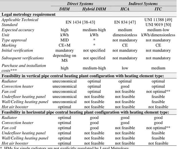
Table 1.1 - Heat accounting systems feasibility in space heating and cooling plants.
Direct Systems Indirect Systems
DHM Hybrid DHM HCA ITC
Legal metrology requirement
Applicable Technical
Standard EN 1434 [38-43] EN 834 [47]
UNI 11388 [49] UNI 9019 [50]
Expected accuracy high medium-high medium medium-low
Unit kWh kWh dimensionless kWh/dimensionless
Type approval MID * not mandatory not mandatory
Marking CE+M * CE CE
Initial verification mandatory not specified not mandatory not mandatory
Subsequent verifications depending on
MS not specified not mandatory not mandatory
Purchase and installation
costs*** high medium-high low medium
Feasibility in vertical pipe central heating plant configuration with heating element type:
Radiator uneconomical optimal optimal optimal
Convection heater uneconomical optimal good optimal
Fan coil uneconomical optimal not feasible not optimal**
Underfloor heating panel uneconomical not feasible not feasible feasible
Wall/Ceiling heating panel uneconomical not feasible not feasible feasible
Hot air booster optimal not feasible not feasible not feasible
Feasibility in horizontal pipe central heating plant configuration with heating element type:
Radiator optimal good good good
Convection heater optimal good good good
Fan coil optimal good not feasible not optimal**
Underfloor heating panel optimal not feasible not feasible feasible
Wall/Ceiling heating panel optimal not feasible not feasible feasible
Hot air booster optimal not feasible not feasible not feasible * HMs for single radiators are not explicitly regulated by Legal Metrology
** feasible only for fan coils at fixed velocity
***costs considered for single device; the final cost depends on the number of HEs within the apartment
1.1.1 Direct Heat Meters
DHMs measure the thermal energy delivered to a given Heating Element (HE) through the flow and return pipes of the heating/cooling circuit. DHMs perform a simple thermal energy balance on the HE under the following assumptions: i) stationary and one-dimensional flow in the measurement sections; ii) a single inlet and a single outlet (i.e. the absence of leaks and fluid withdrawals); iii) negligible variation of kinetic and potential energy within the HE’s flow/return pipes. In the typical operating conditions, the measurement of thermal energy (E) in a given time interval can be carried out as per equation (1.3).
14
𝐸 = ∫ 𝜌 𝑐̅𝑝 𝑞 ∆𝑇 𝑑𝜗 (1.3)
Where 𝝆 is the flow density, 𝒄̅𝒑 is the average specific heat capacity of the fluid, 𝒒 is the volumetric flow rate, ∆𝑻 is the temperature difference between the flow and return pipes. The measuring system can be made up of a single indivisible unit or of differen sub-assemblies separately homologated (i.e. a flow sensor, a pair of temperature sensors, a calculator, as per Figure 1.1). DHMs are regulated by legal metrology [36] and detailed harmonized technical standards [38-46].
Figure 1.1 – DHMs constructive scheme
For major details about applicable technical regulations for DHMs, the reader should refer to Table 1.2.
Table 1.2 – Reference standard for DHMs
Reference Title
EN 1434-1:2016 Heat meters – Part 1: General requirements
EN 1434-2:2016 Heat meters – Part 2: Constructional requirements
EN 1434-3:2016 Heat meters – Part 3: Data exchange and interfaces
EN 1434-4:2016 Heat meters – Part 4: Pattern approval tests
EN 1434-5:2016 Heat meters – Part 5: Initial verification tests
EN 1434-6:2016 Heat meters – Part 6: Installation, commissioning, operational
monitoring, maintenance
OIML R75-1:2002 Heat meters – Part 1: General requirements
OIML R75-2:2002 Heat meters – Part 2: Type approval tests and initial verification tests
15
Thus, according to the MID, it is possible to classify DHMs into three main categories:
− DHMs installed within residential buildings; generally not remotely read, with mechanical single-jet flow meters and with short-stem temperature sensors (mounted directly on the pipeline) with an accuracy class 3;
− DHMs installed on the supply points of bigger utilities; generally with static flow meters and long-stemmed temperature sensors (mounted directly on the thermowell) with an accuracy class 2;
− DHMs installed on the supply points of larger users (i.e. super-condominiums, hospitals, industrial users); generally remotely read, of the combined type, with static flow meters and long stem temperature sensors mounted on the well, with an accuracy class 1 or 2.
Depending also on the flow rate, the scope and the type of application of DHMs (i.e. residential, commercial, industrial etc.), another classification can be applied depending on the flow meter type. As highlighted by Choi, et al. [54] by summing sales data from Germany, Denmark, UK, Finland and Sweden the main types of flowmeter used in heat energy metering are: turbine, electromagnetic, ultrasonic, with average market shares between 2002 and 2006 of respectively 37.6%, 38.4% and 24.0%.
Depending on technical characteristics of the building heating plant and/or on architectural constraints, the installation of DHMs in not always technically and or economically feasible as for example in historical buildings, centralized heating systems with vertical mains etc. where it would be required to install a heat meter for each heating element [32].
16
1.1.2 Metrological issues of DHMs
The Measuring Instruments Directive (MID “recast”) (2014/32/EU) fixes rules for the approval and initial verification of heat meters in terms of essential requirements and maximum permissible errors in its Annex VI “Thermal Energy Meters MI-004”. Technical specification about the metrological performance, pertain to the corresponding national standards implementing the European harmonized standard (or OIML recommendations). For heat meters, these standards are EN 1434 and OIML R75 series. The Maximum Permitted Error, as per relevant applicable standards, are given in Table 1.3.
Table 1.3 – Maximum Permitted Errors for DHMs
Class MPE Flow sensor MPE Temperature sensor MPE calculator MPE DHM System 1 (𝟏 + 𝟎. 𝟎𝟏𝒒𝒑 𝒒) ∗ 𝟎. 𝟓 + 𝟑 ∆𝑻𝒎𝒊𝒏 ∆𝑻 𝟎. 𝟓 + ∆𝑻𝒎𝒊𝒏 ∆𝑻 (𝟏 + 𝟎. 𝟎𝟏𝒒𝒑 𝒒) ∗ + 𝟏 + 𝟒∆𝑻𝒎𝒊𝒏 ∆𝑻 2 (𝟐 + 𝟎. 𝟎𝟐𝒒𝒑 𝒒) ∗ (𝟐 + 𝟎. 𝟎𝟐𝒒𝒑 𝒒) ∗ + 𝟏 + 𝟒∆𝑻𝒎𝒊𝒏 ∆𝑻 3 (𝟑 + 𝟎. 𝟎𝟓𝒒𝒑 𝒒) ∗ (𝟑 + 𝟎. 𝟎𝟓𝒒𝒑 𝒒) ∗ + 𝟏 + 𝟒∆𝑻𝒎𝒊𝒏 ∆𝑻
*in any case no more than 5%
𝒒𝒑 with stationary flows, ∆𝑻𝒎𝒊𝒏 lower limit of the temperature difference for the correct functioning of the DHM
For each sub-unit of the heat meter (flow sensor, temperature sensors and calculation module). There are specific installation and management issues affecting its on-field metrological performance, as following [55-61]:
1. installation effects, which are fluid-dynamic (i.e. occurring due to disturbances upstream and downstream of the heat meter) or thermal (i.e. thermal disturbances affecting the temperature sensors pair, such as inadequate immersion depth of the sensor causing conductive heat transfer with the pipe); 2. the presence of gas or impurities in the heat transfer fluid which can interact significantly with the heat meters by causing chemical reactions with alteration
17
of the characteristics of the fluid, corrosion phenomena, biological phenomena, fouling etc.;
3. the influence of the metrological characteristics from the thermodynamic operating conditions of the heat transfer fluid; these are calculated by the calculator module basing only on the measured temperature; however, the fluid may be a mixture of water and additives, with variable thermophysical properties (depending on the composition and the type of additive), and its characteristics in centralized heating systems can change greatly over time; 4. the potential use of measuring instruments outside its optimal measuring range;
as for example the over-sizing of the maximum thermal heating power may result in the non-optimal functioning of the measurement system: in critical conditions the meter could work with too low flow rates or with a too low temperature difference.
Unfortunately, the installation effects are not fully regulated by legal metrology, thus a number of scientific papers have been produced with respect to on-field metrological characterization of DHMs, which are summarized in Table 1.4.
Table 1.4 – Scientific literature about DHMs on-field characterization
Subject Main outcomes Reference
DHMs installation effects, recalibration periods, accuracy over time
Meters correctly installed are accurate within MPE of MID.
Flow meter is relatively resilient to incorrect installation
Installation of temperature sensor pair is critical
Butler, et al. [61]
DHMs on field test accuracy, accuracy over time
Significant reductions in the heat meters performance AGFW [62] DHMs on field test accuracy, installation effects (position, rotation, vibration), durability test, accuracy over time
Electromagnetic and ultrasonic types have better performances than turbine one.
Tested meters showed adequate durability. Deviations of the turbine and ultrasonic flowmeters during on-field tests were within ±2.5%.
Electromagnetic flow-meter’s accuracy within 6.9% of mean flow rate.
Choi, et al. [54]
Accuracy of DHMs over time
Need of correction factors specifically designed for local plant installation characteristics.
Celenza, et al. [63]
Increasing metrological performances of DHMs
A new method to increase the measuring range of the flow sensor is proposed, consisting of mixing heat fluxes in a heat exchange circuit at the point in which the heat carrier is supplied to the exchanger.
Michnikowski and Deska [64]
18
Electronic heat cost allocators
Electronic HCAs are currently the most popular among indirect heat accounting devices. Such devices may only be used on radiators/convectors for which the emitting surface is accessible and they are applied to the radiating surface of the radiator in a suitable position to detect its average temperature. First HCAs available on the European market were based on the evaporation principle and, although still regulated by EN 835 [48], are now virtually obsolete because lacking of remote reading and needing annual maintenance to refill the evaporated fluid. Modern HCAs are completely electronic and they are regulated by EN 834 [47]. Electronic HCAs normally consist of a compact case composed by the following components: i) a calculation and data transmission module; ii) one or more temperature sensors (of which the one for the ambient temperature in some configurations is external to the case); iii) a display; iv) a power supply system; v) a metal plate for the installation and thermal coupling (Figure 1.2).
Figure 1.2 – Electronic HCA constructive scheme
Thus, heat accounting is based on the integration over time of the temperature difference between the radiator surface and the room ambient in which the HCA is installed. EN 834 [14] describes the following three types of HCAs:
− single sensor HCA, which measures the room heating surface or heating medium and use the conventional ambient temperature (20 °C);
− two-sensors HCA, made-up by one sensor that measures the room heating surface or heating medium and a second one measuring the ambient or a related temperature;
19
− multiple-sensor employing at least two sensors for the room heating surface or heating medium and one sensor for the ambient temperature.
The EN 834 [14] standard does not provide explicitly any algorithm for the calculation of the Allocation Units (AUs) of each radiator but, to this aim, describes two methods: i) non-rated displayed reading; ii) rated displayed reading. In the first, the AUs of each radiator are estimated on the basis of the time integral of the measured temperature difference between the radiator heating surface and the room. In the second, allocation units for the i-th radiator in the j-th apartment of the building are obtained from the non-rated displayed reading values by multiplication by rating factor KC, KQ and KT for each radiator, through the following equation:
𝐴𝑈𝑟𝑎𝑑 = 𝐾𝐶𝐾𝑄𝐾𝑇∫ (∆𝑇 60) 𝑛 𝑑𝜃 𝜃 (3)
where KC and KQ represent respectively rating factors at reference laboratory conditions of: i) the temperature sensors coupling; ii) the rated heat output of the radiator. Factor KT is used only for single sensor HCAs when indoor temperature is less than the ambient reference one.
In particular, rating factor KC takes into account that HCAs do not measure the actual temperature difference between the heat transfer fluid and room ambient, but actually a value proportional to it. This is mainly due to the following issues: i) the surface temperature measured in a specific point is different from the average surface temperature of the radiator; ii) the contact resistance between the plate and the radiator influences the measurement of the surface temperature; iii) in two-sensors HCAs the measurement of room ambient temperature is influenced by convective and radiative fluxes into the case.
Therefore, rating factor KC is a function of the HCA characteristics, of the radiator type (but not of its rated heat output) and of the installation conditions. In particular, installation conditions are generally different from those at laboratory. Therefore, KC at actual conditions of use can greatly differ from the one estimated by the manufacturer at rated conditions, especially when the installation is not carried out in accordance with specific technical instructions (e.g. wrong positioning, not adequate
20
coupling plate-radiator). Rating factor KQ, however, concerns the rated thermal output of the radiator. At rated installation and operative conditions, KQ is a function solely of the radiator characteristics (i.e. type and size). Unfortunately, rarely installation and operative conditions are equal to the rated ones, thus the actual heat emitted by the radiator is affected also by installation conditions, hydraulic connections and surface painting. As a matter of fact, actual value of KQ may differ from that estimated by the designer of the heat allocation system, both for the impossibility to accurately estimate rating factors at real actual conditions of installation and use and for the lack of fair and traceable certification of existing radiators. Table 1.5 summarizes main technical characteristics of HCAs in the market.
Table 1.5 - Technical characteristics of HCAs
Description Type Comment
Temperature sensors
1 or 2 sensors with external sensor
HCAs are equipped with sensors embedded into the case or with an external remote sensor for radiators not easily accessible. HCAs normally use one or two temperature sensors. In the first case the sensor (positioned in the back side and directly fixed on the plate) only measures a surface temperature
proportional to the radiator one (assuming that the ambient temperature is set equal to 20°C). In the second case, in addition to the first sensor, a second one (on the front side of the HCA) measures a temperature proportional to the ambient one. Thus, allocation units are calculated through the difference between the two measured temperatures.
Software Programmable
Not programmable
Rating factor K is calculated as a function of the characteristics of the radiator. Such factor depends on the radiator heat output and size (height, width and depth), on the material (cast iron, steel, aluminum), on the type (shape and finning of the elements). Also, the type and size of valve and holder and the thermal contact HCA-radiator are to be adequately evaluated. EN 834 requires K to be directly programmed in the HCA's memory (in such case, the units of each HCA are proportional to heat consumptions) or not-programmed (in such case, the units of each HCA are subsequently multiplied by the specific K). Only in the first case the reading will be the allocation unit itself. In such case, allocation units will be visible and the user should aware of his own consumptions.
Reading Local
Remote (walk-by)
Readings can be performed from inside or outside single apartments. There are mainly two remote reading methods available: i) data are remotely
21
Description Type Comment
Automatic Remote reading
downloaded by an operator without entering the apartment; ii) HCA is equipped with a radio module permanently connected via web or GPRS to a concentration unit at fixed frequencies.
Power Normal/long life
batteries.
Permanent/changeable
One of the most important issues is the battery life (normally ranging 5 to10 years) and/or battery replacement to avoid complete HCA substitution.
Tampering Seal (mechanical/
electronic) - Alarm
To prevent tampering, electronic HCAs are equipped both with seals and alarms detecting abnormal operative situations (fraudulent use).
Sensitivity to external heat sources
HCAs should be insensitive to external heat sources or recognize contributions from free heat sources (e.g. solar radiation, heaters) and from the heating plant itself.
1.1.3 Insertion time counters
In Italy, the first indirect heat accounting systems in multi-apartment buildings supplied by a central heating recorded the opening times of the zone valves. The technological evolution has subsequently allowed the development of more complex and effective solutions which are not related solely to the opening times of the zone valve. Nowadays, such systems together with an effective balancing of the heating plant, allow the compensation of opening times on the basis of: i) the temperature difference between the heating thermal fluid and the environment (Insertion Time Counter – Temperature Compensated, ITC-TC); ii) the actual Degree-Days (Insertion Time Counter Compensated with Degree Days, ITC-DD). These systems are used in central heating plants controlled by zone valves or by on-off valves installed on each heating terminal unit. In particular, ITC-TCs are made up of: i) a calculation and data transmission device; ii) a thermostatic valve combined with an actuator (for each zone or heating element); iv) an on-off sensor on the valve for the control of opening times; v) two sensors for flow and return temperature (installed in the boiler room) of the heating thermal fluid; vi) an ambient temperature sensor (optional). On the other hand, ITC-DDs, instead of the temperature sensor for each controlled environment, rely on a unique external temperature sensor for measuring the actual degree-day. Such
22
systems are regulated only at technical level by national standards UNI 11388 [49] and UNI 9019 [50] for ITC-TC and ITC-DD respectively.
For ITC-TC, according to the standard UNI 11388 [49], the 𝐴𝑈𝑜𝑝,𝑘 of each i-th single zone/radiator is given by equation (1.4)
(𝐴𝑈𝑜𝑝,𝑘) 𝑖 = 𝐾 𝑄̇𝑖∫ ( 𝑇𝑓,𝑜𝑝− 𝑇𝑎𝑖𝑟,𝑖𝑛 𝑇𝑓,𝑐− 𝑇𝑎𝑖𝑟,𝑖𝑛,𝑐) 𝑛 𝑑𝜃 𝜃𝑜𝑝,𝑘 (1.4)
where: i) 𝑄̇𝑖 is the nominal heat output of the zone/radiator, ii) 𝑇𝑓,𝑜𝑝 is the temperature of the heating thermal fluid averaged on flow and return pipes and measured during the actual opening time of the valve 𝜃𝑜𝑝,𝑘, iii) 𝑇𝑎𝑖𝑟,𝑖𝑛 is the indoor air temperature (measured or set equal to 20°C), iv) 𝑇𝑓,𝑜𝑝,𝑐 and 𝑇𝑎𝑖𝑟,𝑖𝑛,𝑐 the corresponding conventional temperatures; v) 𝐾 is a corrective factor between (𝐴𝑈𝑜𝑝,𝑘)
𝑖 and the effective heat consumed, whose estimation is described in par. 9.3 of UNI 11388 [49]. The standard also takes into account the heat exchanged during the k-th transient of valve closure. This scheme runs out normally in a time equal to 5 times the time constant of the heating body and the heat exchanged during this time is calculated through equation (1.5) (𝐴𝑈𝑐𝑙,𝑘)𝑖 = 𝐾 𝑄̇𝑖( 𝑇𝑓,𝑐𝑙− 𝑇𝑎𝑖𝑟 𝑇𝑓,𝑐− 𝑇𝑎𝑖𝑟,𝑐) 𝑛 ∫ 𝑒−𝑛𝜃𝜏 𝑑𝜃 𝜃𝑐𝑙,𝑘 = 𝐾 𝑄̇𝑖( 𝑇𝑓,𝑐𝑙− 𝑇𝑎𝑖𝑟,𝑖𝑛 𝑇𝑓,𝑐 − 𝑇𝑎𝑖𝑟,𝑖𝑛,𝑐 ) 𝑛 𝜏 𝑛(1 − 𝑒 −𝑛𝜃𝐶𝑉,𝑘𝜏 ) (1.5)
where: i) 𝑇𝑓,𝑐𝑙 is the the temperature of the heating thermal fluid averaged on flow and return pipes and measured at the closure of the valve, ii) 𝜏 is the time constant of the heating body, iii) 𝜃𝑐𝑙,𝑘 is the time of closure of the valve. When the valve is opened before the end of transient, ITC-TC automatically switches on equation (5). Time constant τ of heating bodies normally ranges 0.15 (convection heater) to 10 hours (not insulated underfloor heating panel) [16]. It can be estimated on the basis of the ratio between heat capacity and thermal transmittance of the heating body at reference
23
conditions. The total (𝐴𝑈)𝑖 is simply given by the sum of the 𝐴𝑈𝑜𝑝,𝑘 and 𝐴𝑈𝑐𝑙,𝑘 measured during the opening and closure times of the valve, as per equation ((1.6).
(𝐴𝑈)𝑖 = (𝐴𝑈𝑜𝑝,𝑘)
𝑖 + (𝐴𝑈𝑐𝑙,𝑘)𝑖 (1.6)
Technical standard UNI 11388 [49] sets maximum permissible errors for temperature and time measurements equal to ±1°C and ±0.5% respectively.
For ITC-DD, according to the standard UNI 9019 [50], the 𝐴𝑈𝑜𝑝,𝑘 of each i-th single zone/radiator is given by equation (1.7)
(𝐴𝑈)𝑖 = 𝐾 ∑ 𝑄̇𝑖 𝑛 𝑘=1 ( 𝐷𝐷𝑖 𝑇𝑎𝑖𝑟,𝑖𝑛,𝑐− 𝑇𝑎𝑖𝑟,𝑜𝑢𝑡,𝑐) [𝜃𝑜𝑝,𝑘+ 𝜏 (1 − 𝑒 −𝜃𝑐𝑙,𝑘𝜏 )] (1.7)
where: i) 𝐷𝐷𝑖 is the actual degree-days measured during the opening time of the valve and equal to the difference between indoor (𝑇𝑎𝑖𝑟,𝑖𝑛) and outdoor (𝑇𝑎𝑖𝑟,𝑜𝑢𝑡) air temperature, ii) 𝑇𝑎𝑖𝑟,𝑖𝑛 and 𝑇𝑎𝑖𝑟,𝑜𝑢𝑡 are the conventional indoor and outdoor air temperatures, respectively, iii) 𝜃𝑜𝑝,𝑘 and 𝜃𝑐𝑙,𝑘 are the opening and closure times of the valve in the k-th period, iv) 𝜏 is the time constant of the heating body. K is the corrective factor between (𝐴𝑈)𝑖 and the effective heat consumed, whose estimation is not described in [50].
1.2 Metrological issues for distributed IHASs
Figure 1.3 shows the typical operative scheme of a distributed heat accounting system with several HCAs in a building served by a central heating plant with vertical mains.
![Figure 2.1 – Existing scientific literature regarding individual metering systems’ energy saving, (°) papers reviewed in [25]; (*) papers reviewed in [24]](https://thumb-eu.123doks.com/thumbv2/123dokorg/4691617.44279/57.892.193.762.280.948/existing-scientific-literature-regarding-individual-metering-reviewed-reviewed.webp)