1
Dottorato di Ricerca in Ingegneria dei Prodotti e dei
Processi Industriali
XXX cycle
University of Naples Federico II
Manipulation of polymeric fluids
through
pyro-electro-hydro-dynamics
Federico Olivieri
Department of Chemical, Materials and Production Engineering
Tutor : Prof. Giuseppe Mensitieri
Co-tutor : Prof. Andrea D’Anna – Dr. Pietro Ferraro
2
Summary
Aim of the work ... 4
CHAPTER 1 - PYRO-ELECTRO-HYDRO-DYNAMICS ... 6
1.1. Pyroelectric effect ... 7
1.1.1 Pyroelectric materials and properties ... 8
1.1.2 Analytical interpretation of pyroelectricity ... 9
1.2. EHD phenomenon ... 11
1.2.1 Surface tension ... 11
1.2.2 Electric external forces ... 12
1.2.3 Equilibrium condition ... 13
1.3. Pyro-EHD effect ... 14
References ... 15
CHAPTER 2 - POLYMERIC MICRO-LENSES OBTAINED BY PYRO-EHD EFFECT ... 19
2.1. Micro-lenses applications and conventional fabrication ... 20
2.1.1 Overview and soft lithography ... 20
2.1.2 Electric field techniques ... 23
2.2. Pyro-Ink-Jet printing of micro-lenses... 24
2.2.1 Ink-Jet printing: overview ... 24
2.2.2 Pyro-EHD printing ... 28
2.2.3 Forward Pyro-EHD printing configuration ... 35
2.3. Paper: “Direct Fabrication of Polymer Micro-lens Array” ... 37
2.3.1 Abstract ... 38
2.3.2 Introduction ... 38
2.3.3 Pyro-EHD printing: setup evolution... 39
2.3.4 3D PDMS micro-lenses onto micro-fluidic chip ... 41
2.3.5 Conclusions ... 45
2.4. Micro-engineered pyroelectric crystal and self-assembling of micro-lenses……….. ... 46
3
2.4.2 Polymer self-assembling on PPLN... 47
2.4.3 Microstructure characterization ... 50
2.4.4 Self-assembled micro-structure functionalization ... 60
2.5. Paper: “Direct self-assembling and patterning of semiconductor quantum dots on transferable elastomer layer” ... 63
2.5.1 Abstract ... 64
2.5.2 Introduction ... 64
2.5.3 Fabrication process ... 66
2.5.4 Conclusions ... 75
References ... 76
CHAPTER 3 - TETHERED PYRO-EHD SPINNING (TPES) FOR POLYMER FIBERS PRINTING: MICRO-CHANNELS FABRICATION ... 86
3.1. Fibers patterning through TPES ... 87
3.2. Paper: “Direct Writing of Microfluidic Footpaths by Pyro-EHD Printing” ... 89
3.2.1 Abstract ... 90
3.2.2 Introduction ... 90
3.2.3 Experimental section ... 93
3.2.4 Results and discussion ... 97
3.2.5 Conclusions ... 101
References ... 103
4
Aim of the work
This thesis is focused on the manipulation of liquids and polymeric fluids in a non-contact and electrode-free way, exploiting pyro-electro-hydro-dynamic effect. In the following, there will be described the pyro-electro-hydro-dynamic techniques, their possible applications in different field of technology and the obtained results. It will be showed as the versatility of these methods makes pyro-electro-hydro-dynamics very attractive to many scientific fields, such as optics, microfluidics, biology and chemistry. All the reported works were developed at CNR-ISASI laboratories. The thesis structure provides an introduction based on the theory and the combination between pyroelectric and electro-hydro-dynamic effect, with a focus on the developed techniques, followed by the presentation of the realized works.
Specifically, in Chapter 1 the theory and the basis of the pyro-electro-hydro-dynamics will be explained; it will be shown its potential and how we propose to use this combined effect.
In Chapter 2 it will be presented the fabrication of micro-optical devices, in particular micro-lenses, through pyro-electro-hydro-dynamic effect. Micro-lenses find application in communications, three-dimensional displays, optical data storage and photo-detectors. In the second chapter the micro-lens fabrication will be described using two different approaches: first, by an ink-jet technology, and then through self-assembly on a micro-engineered pyroelectric crystal. Starting from the need to simplify the electro-hydro-dynamic printing technology and increase the range of printable materials, a new pyro-ink-jet set-up will be proposed, which will permit to avoid the use of electrodes and nozzle. Then, further modifications of the set-up will improve the flexibility of the technique, for example extending the range of suitable substrates. After that, the micro-lenses will be optically and geometrically characterized and it will be presented the fabrication of a multi-component device as an example of application of this technique. The results demonstrate that pyro-ink-jet printing permit to realize very uniform micro-lenses arrays with high resolution (diameter ̴ 300 nm). The second approach proposed is based on the self-assembly of a micro-lenses array on a micro-engineered pyroelectric crystal. It will be showed the fabrication of a micro-lens array decorated by nano-particles, such as quantum dots, and it will be discussed the di-electro-phoretic effect for the self-assembling of the employed dots. In particular, the study will focus on the effect of the patterned substrate on the localization of the nano-particles and on the investigation of the dots pattern transfer. The most attractive application of these nano-composites is in optic and
5 photonic sectors: quantum dots, in fact, find great interest in solar cells and energy harvesting.
Chapter 3 will show another application of pyro-ink-jet printing: the capability of this system in the manipulation of highly viscous polymeric solution, allowing the deposition of polymeric fibers. The results presented demonstrate that pyro-ink-jet printer is also a valid alternative to the classic electro-spinning system, avoiding electrodes and spiraling effect during the deposition. The fibers produced show great uniformity and reach thicknesses until the nano-metric scale. The possibility to use biodegradable and biocompatible polymers ensures large application in attractive fields such as biology, chemistry and microfluidics. Moreover, in this chapter it will be shown how a polymeric fiber, deposited through pyro-ink-jet printing, can be used as a component in a microfluidic channel, fabricated subsequently to the fiber deposition. Finally, all the procedures used to realize micro-channel will be illustrated.
6
CHAPTER 1
PYRO-ELECTRO-HYDRO-DYNAMICS
7
1.1 Pyroelectric effect
Pyroelectricity is a property of particular materials which exhibit a spontaneous polarization that depends on the temperature1. This property depends on the molecular structure of the material: a pyroelectric solid has inner dipoles, due to the presence of cations or anions in the structure2. As shown in Fig. 1.1, in equilibrium conditions (constant temperature), each dipole has its orientation and the total electric dipole moment is zero. A temperature variation induces a movement between the atoms (which have a certain mobility) and, for that reason, a change in the dipoles strength (therefore, the polarity3) and, consequentially, a charge displacement on the material surface, i.e. an electric current.
Figure 1.1. Circuital representation of pyroelectric working at constant
temperature, under heating and under cooling.
It is important to underline that, if the material remains at the same temperature, after it has undergone to a thermal variation, the inner domains work to recover an equilibrium, crowding the charges on the external surfaces, reinstating the starting polarization and setting to zero the electric field. That means just a thermal gradient induces an electric current2,4. Thermoelectricity shows similar characteristics, compared to pyroelectricity. Nevertheless, while a thermoelectrical material, once heated, produces an electric current and a stable electrical potential, due to the inner displacement of electrons and holes5, a pyroelectric material attracts electrons from the external ambient, in order to compensate the exceed of charges occurred on the surface2. The phenomenon depends on the set temperature: in fact the Curie temperature is the temperature at which the polarization goes to zero1,6.
8
1.1.1 Pyroelectric materials and properties
1.1.1.1
Pyroelectric material classes
A pyroelectric material can be either a ceramic or a polymer. Between ceramics there are lead zirconate titanate (PZT, Pb[ZrxTi1-x]O3), barium titanate (BaTiO3),
lithium titanate (LiTiO3), lithium niobate (LiNbO3), lithium tantalate (LiTaO3) 7
or the more complex lead magnesium niobate-lead titanate (yPbMgxNb1-xO3
–1-yPbTiO3, PMN-PT) and lead zirconate niobate-lead titanate (yPbZrxNb1-xO3
–1-yPbTiO3, PZN-PT) 8-11
. PZT based ceramics are probably the most common used, due to its chemical and mechanic stiffness, their high Curie temperatures (suitable, for example, for space applications) and, moreover, the variation of the Zr/Ti ratio, combined to the addition of dopants, allows to largely modify the physical properties of the material2,12. Pyroelectric polymers include polyvinylidene fluoride ((C2H2F2)n, PVDF), polyvinylidene fluoride
trifluoroethylene ((C2H2F2)n-((C2HF3)m, P(VDF-TrFE), which have the highest
pyroelectric coefficient ever signed: 40μC/m2K)13 and polyvinylidene fluoride trifluoroethlyenechlorofluoroethylene ((C2H2F2)n-((C2HF3)m-(C2H2FCl)p,
P(VDF-TrFE-CFE))7,14. Obviously, in order to be pyroelectric, a polymer has to be semi-crystalline. That is a critical point because PVDF can crystallize in a α, β and γ-phase, and the more stable phase is the α one, which is paraelectric. Moreover, without external stresses, PVDF crystallizes in the α-phase too. Instead, β-phase exhibits the strongest pyroelectric properties15, while γ-phase have chain conformation in between that of the α and β-phases, showing weak pyroelectric properties. The way to obtain one of the pyroelectric phases goes through the structure mechanic deformation and the poling (an electric process that attends to the polarization and the dipole moments orientation in the direction of an applied external electric field and that will treated in the following sections)7,15. It is also possible to obtain a δ-phase simply poling the α-phase, making it polar15. Compared to PVDF, the pyroelectric β-phase of P(VDF-TrFE) is achieved without external stresses16. Furthermore, P(VDF-TrFE) has a Curie temperature lower and a dielectricity 25 times greater than the ones of pyroelectric ceramics
17-18
; these properties make this polymer suitable for particular application such as power generation or low temperature harvesting. Pyroelectric polymers have the advantage of being very cheap and easy to manipulate, allowing to work at low temperature. Their use occupies, in particular, biomedical and industrial fields
6-7,19
9 tourmaline, probably the first pyroelectric material ever discovered20 or quartz2) or biological materials (such as bones or tendons)2,21-22.
1.1.1.2
Pyroelectricity, piezoelectricity and ferroelectricity
A pyroelectric is always a piezoelectric also, due to the existence of polarizable domains. Not all the piezoelectric materials are pyroelectric too; this is caused by the inner structure of pyroelectrics. In fact, a pyroelectric crystal is asymmetric, while the charges accumulation occurs along orthogonal faces relative to a symmetry axis. Indeed, some piezoelectric crystals have a symmetry that prevents pyroelectricity. Moreover, ferroelectric materials are also pyroelectrics, being able to reverse their spontaneous polarization if submitted to an electric field7. However, not all the pyroelectric materials can invert their polarization in the same conditions23. More in general, there are 32 classes of dielectric crystals, 21 of these are not symmetrical and 20 are piezoelectric. Among these, 10 are paraelectrics (do not exhibit a spontaneous polarization, but only in presence of external electric fields), while the other 10 are pyroelectrics. Therefore, these are divided in ferroelectrics and non-ferroelectrics7. In Fig. 2.1 is showed a recapitulative scheme:
Figure 1.2. Classification of crystals: piezoelectrics, pyroelectrics and
ferroelectrics: 10 of the 32 dielectric crystal classes are pyroelectric.
1.1.2 Analytical interpretation of pyroelectricity
The dependence of the spontaneous polarization PS (C/m2
) from the temperature is described by the pyroelectric coefficient 𝑝̅ (C/m2·K), which is a vector expressed as:
𝑝̅ = (𝜕𝑃̅̅̅̅𝑆
10 where E is the electric field, expressed in V/m, and σ is the elastic stress, expressed in Pa. More precisely, 𝑝̅ reported in Eq. 1 is named pyroelectric thermodynamic coefficient, while pe showed in Eq. 2 is the pyroelectric
experimental coefficient and is calculated as the variation of charges due to a thermal variation dQ/dT on a surface A24-25.
𝑝𝑒=1𝐴𝑑𝑄𝑑𝑇 (2)
Note that the pyroelectric experimental coefficient is a scalar and its value is usually lower than the modulus of 𝑝̅. The electric displacement D of the atoms is the effect of pyroelectricity in a material and can be expressed as2:
𝑑𝐷̅ = 𝑝̅𝑑𝑇 (3) That means that, if E is constant, D is equal to PS. This is clear considering the
formula that expresses D for an isotropic pyroelectric material3,26:
𝐷̅(𝐸, 𝑇) = 𝜀0𝜀𝑟(𝑇)𝐸̅ + 𝑃̅ (𝑇) (4) 𝑆
where ε0 is the vacuum permittivity (= 8.854x10 -12
C/V⋅m) and εr(T) is the relative
permittivity of the material at electric field E and temperature T.
Known IP as the electric current generated by pyroelectric materials submitted to
a thermal treatment (see Fig. 1.1), its expression can be written (considering linear behaviors relative to the heating or cooling27) as:
𝐼𝑃= 𝐴|𝑝̅|𝑑𝑇𝑑𝑡 (5)
where A is the stimulated surface on the material28-29. The current generated by pyroelectric materials, at the best, is in the range of micro-amperes, but, normally, it does not exceed pico-amperes. However, the evaluation of pyroelectricity is made considering constant the volume of the material, during the thermal treatment: this effect is called primary pyroelectricity. When a thermal gradient is applied on the material, its volume changes, so all the parameters that concern the geometry are altered and a secondary pyroelectricity occurs, due to the piezoelectric effect2,30.
11
1.2 EHD phenomenon
Electro-hydro-dynamics (EHD) is a phenomenon that describes the interactions of ionized particles into a liquid subjected to an electric field. A charge displacement is induced in the liquid due to the electric field that employs attractive and repulsive forces with the liquid molecules31-32. The result consists on the deformation of the liquid drop that assumes a conical shape, known as Taylor’s cone33, due to charges accumulation at the interface34-35.
Figure 1.3.Taylor’s cone.
In particular, Taylor’s cone is an equilibrium condition mediated by the forces generated by the surface tension force and the external electric force density33. In other words, an equivalence between a term 𝐹𝛾, relative to the surface tension contribute, and a term 𝐹𝑒, relative to the electric external stimulus, has to be
reached35. In this section the Taylor’s cone equilibrium conditions will be summarized. These are at the basis of the phenomena involved in the pyro-EHD tools, explained in the following.
1.2.1 Surface tension
The surface tension is generically defined as the external exerted work 𝜕𝑊 to expand the liquid surface for a quantity 𝜕𝐴:
𝛾 =𝜕𝑊
𝜕𝐴 (6)
If the surface is curved, choosing the z axis as the direction of the force associated to the surface tension, 𝛾 can be written as:
𝛾 =|𝐹̅̅̅̅|𝑍 𝐴 ( 1 𝑅𝐶1+ 1 𝑅𝐶2) −1 (7)
Where 𝑅𝐶1 and 𝑅𝐶2 are the curvature radii. In the case of a cone, as that showed in Fig. 1.4, 𝑅𝐶2 → ∞.
12 𝛾 =|𝐹̅̅̅̅|𝑍 𝐴 𝑅𝐶1= |𝐹̅̅̅̅|𝑍 𝐴 𝑟 cot 𝛼 (8)
Figure 1.4. Schematization of a Taylor’s cone.
The 𝐹𝛾 modulus could be defined as the normal force 𝐹𝑧 per unit area A, so Eq. 8 can be also written:
|𝐹̅ | = 𝛾 |𝐹̅̅̅̅|𝑍
𝐴 = 𝛾 cot 𝛼
𝑟 (9)
1.2.2 Electric external forces
In order to evaluate 𝐹𝑒, the first step is the calculation of the electric force density 𝑓̅ , which is linked to the Maxwell stress tensor 𝑇̿. 𝑒
𝑓̅ = ∇̅ ⋅ 𝑇̿ (10) 𝑒
In order to derivate 𝑇̿, two possible approaches are known as the Kelvin method and the Korteweg-Helmholtz method36-37. These proposals consider magnetic fields as neglected and elementary dipoles as the model to describe the interaction between the fluid and the field. Moreover, the electric field is assumed independent from the mechanic pressure, i.e. electrostriction effects are neglected. By the Kelvin method, the total electric force density of Kelvin 𝑓̅̅̅̅̅ 𝑒,𝑘 could be decomposed in two contributes: one due to the charges bounded to the liquid molecules, 𝑓̅ , associated to the tensor 𝑇̿𝑘 𝑘, and another one due to free
charges, 𝑓̅ , associated to the tensor 𝑇̿𝑓 𝑓36. The evaluation of 𝑓
𝑘
̅ (also known Kelvin force polarization density) considers 𝑚̅ as the average electric dipole moment per unit of volume, which is linear respect to the electric field, if the material is isotropic. An expression of 𝑚̅ is:
𝑚̅ = (𝜀 − 𝜀0)𝐸̅ (11)
where ε is the permittivity of the medium and ε0 is the permittivity of vacuum.
13 ∇̅ ⋅ 𝑇̿̿̿ = 𝑓𝑘 ̅ = (𝑚̅ ∙ ∇̅)𝐸̅ = (𝜀 − 𝜀𝑘 0)(𝐸̅ ∙ ∇̅)𝐸̅ = (𝜀 − 𝜀0) [(∇̅ × 𝐸̅) × 𝐸̅ + 1 2∇̅(𝐸̅ ∙ 𝐸̅)] = 1 2(𝜀 − 𝜀0)∇̅(𝐸̅ ∙ 𝐸̅) (12)
being ∇̅ × 𝐸̅ = 0 for the Gauss theorem38-39. Then, 𝑓
𝑓
̅ can be expressed as:
∇̅ ⋅ 𝑇̿ = 𝑓𝑓 ̅ = (∇̅ ∙ 𝐷̅)𝐸̅ (13) 𝑓 where 𝐷̅ is the charge displacement. Therefore, 𝑓̅̅̅̅̅ is given by: 𝑒,𝑘
𝑓𝑒,𝑘
̅̅̅̅̅ = 𝑓̅ + 𝑓𝑘 ̅ =𝑓 12(𝜀 − 𝜀0)∇̅(𝐸̅ ∙ 𝐸̅) + (∇̅ ∙ 𝐷̅)𝐸̅ (14)
Alternatively, the Korteweg-Helmholtz approach starts by the evaluation of electrostatic energy density 𝑊𝐸 of a dielectric material, subjected to an electric
field, and reaches the same results in terms of 𝑓̅𝑒36,40-41. More precisely, the
electric force density of Korteweg-Helmholtz 𝑓̅̅̅̅̅̅ differs from 𝑓𝑒,𝑘ℎ ̅̅̅̅̅ for a 𝑒,𝑘
quantity:
𝑓𝑒,𝑘ℎ
̅̅̅̅̅̅ − 𝑓̅̅̅̅̅ = −∇ [𝑒,𝑘 12(𝜀 − 𝜀0)𝐸̅2−12𝜌 (𝜕𝜀𝜕𝜌) 𝑇𝐸̅
2] (15)
However, the term reported in Eq. 14 is associated to the electrostriction force, which is supposed to be negligible, then 𝑓̅̅̅̅̅̅ ≈ 𝑓𝑒,𝑘ℎ ̅̅̅̅̅ ≡ 𝑓𝑒,𝑘 ̅𝑒36,41. Being 𝐹̅ the total 𝑒
electric force acting on a volume V,it is linked to 𝑓̅ by: 𝑒
𝐹̅ = ∭ 𝑓𝑒 𝑉̅𝑒𝑑𝑉=∭ (∇̅ ⋅ 𝑇̿)𝑉 𝑑𝑉 (16)
1.2.3 Equilibrium condition
Eq. 14 can be simplified considering the normal electrostatic component37 and, applying Eq. 16, is possible to obtain an equation for 𝐹̅ suitable to compare to 𝐹𝑒 𝛾
in Eq. 9. 𝛾cot 𝛼 𝑟 = 1 2𝜀0𝐸𝑧 2 (17)
where 𝐸𝑧 is the normal component of the electric field. Starting from the first two
Maxwell’s laws, 𝐸̅ is linked to an electric potential φ: {∇̅ × 𝐸̅ = 0⇒ 𝐸̅ = −∇̅𝜑
∇̅ ⋅ 𝐸̅ = 𝜌
𝜀0
⇒ ∇2𝜑 = −𝜌
𝜀0 (18)
where ρ is the density. In a cone with equipotential surface,
∇2𝜑 = 0 (19)
A generic solution of Eq. 17 is given by:
𝜑 = 𝑘𝑄̃√𝑟 cos 𝛼 (20) where 𝑄̃ is the Legendre function and k is a constant. The equilibrium is reached when 𝑄̃ is zero and this condition is achieved for 𝛼 = 49.3°. This value is the same empirically deduced by Taylor33. Nevertheless, this result assumes that
14 there are no charges on the cone axis: that means the right solution is an angle slightly smaller42.
1.3 Pyro-EHD effect
If the electric field that activates the EHD phenomenon is generated by a pyroelectric crystal, the combined effect is defined as pyro-electro-hydro-dynamics (pyro-EHD)43-50. The possibility of manipulating liquids or polymeric solutions exploiting pyro-EHD effect, without the use of electrodes, is investigated in the following sections. In this work, two different techniques that exploit the pyro-EHD effect have been used: the first one is based on the dispensing of micro- and nano-drops or micro-fibers, produced by a polymeric (eventually polymeric solution) reservoir placed at a certain distance from a pyroelectric crystal43,45-47,50; the second one consists on the self-assembling of polymeric micro-optical devices onto a micro-engineered lithium niobate LN
44,48-50
. The dispensing is guided by the pyroelectric field that induces a charge displacement on the liquid surface; the reservoir drop turns into a Taylor’s cone shape, until the attractive (or repulsive) force exerted toward the crystal gets start the dispensing of drops or fibers, in order to produce drops arrays or patterns. The self-assembling depends on the pattern impressed onto a LN crystal through a poling treatment. The field lines generated by this crystal induce the polymer to occupy precise positions onto the crystal.
15
References
1 Lang, S. B. Sourcebook of Pyroelectricity. New York: Gordon and Breach Science Publishers. (1974).
2 Lang, S. B. Pyroelectricity: From Ancient Curiosity to Modern Imaging Tool. Physics Today, (2005) 31-36.
3 Lovinger, A. J. Ferroelectric Polymers. Science, (1983) 1115-1121. 4 Whatmore, R. W. Pyroelectric Devices and Materials. Report on
Progress in Physics, (1986) 1335-1386.
5 Kinzie, P. A. Thermocouple Temperature Measurement. New York: J. Wiley (1973).
6 Ramos, P., De Andres, A., and Lopez, S. Effect of Thermal Losses on the Specific Detectivity of Pyroelectric Infrared Detectors. Integrated Ferroelectrics, (2007) 147-159.
7 Lang, S.B. and Das-Gupta, D.K. Handbook of Advanced Electronic and Photonic Materials and Devices. Academic Press, San Diego, CA, (2001) 4.
8 Zhang, R., Jiang, B. and Cao, W. Orientation Dependence of Piezoelectric Properties of Single Domain 0.67Pb(Mn1/3Nb2/3)O3–
0.33PbTiO3 Single Crystal. Applied Physics Letters, (2003) 82, 21, 3737–
3739.
9 Li, Z., Xu, Z., Xi, Z., Xiang, F. and Yao, X. Thermal Expansion Characteristics in [001]-Oriented PMN-0.32PT Single Crystals. Ferroelectrics, (2007) 355, 1, 245–251, 2007.
10 Kumar, P., Sharma, S., Thakur, O.P., Prakash, C. and Goel, T.C. Dielectric, Piezoelectric and Pyroelectric Properties of PMN-PT (68:32) System. Ceramics International, (2004), 30, 4, 585-589.
11 Yasuda, N., Banno, T., Fujita, K., Ohwa, H., Matushita, M., Yamashita, Y., Iwata, M. and Ishibashi, Y. Piezoelectric Properties of Relaxor Ferroelectric Solid Solution Single Crystals PMN-PT and PZN-PT Near MPB Under Pressures. Ferroelectrics, (2007) 347, 1, 44-49.
12 Batra, A. K., Guggilla, P., Currie, J. R., Aggarwal, M. D. and Alim, M. A. Pyroelectric Ceramics for Infrared Detection Applications. Materials Letters, (2006) 1937-1942.
13 Bauer, S., and Lang, S.B. Pyroelectric Polymer Electrets. IEEE Transaction of Dielectrics and Electrical Insulation, (1996) 56, 57–62.
16 14 Chu, B., Zhou, X., Ren, K., Neese, B., Lin, M., Wang, Q., Bauer, F., and Zhang, Q.M. A Dielectric Polymer with High Electric Energy Density and Fast Discharge Speed. Science, (2006) 313, 5785, 334-336.
15 Sencadas, V., Lanceros-Mendez, S., and Mano, J.F. Characterization of Poled and Non-Poled β-PVDF Films Using Thermal Analysis Techniques. Thermochimica Acta, (2004) 424, 201-207.
16 Kouchachvili, L., and Ikura, M., Pyroelectric Conversion-Effects of P(VDF-TrFE) Preconditioning on Power Conversion. Journal of Electrostatics, (2006) 65, 182-188.
17 Olsen, R.B., and Bruno, D.A., Pyroelectric Conversion Materials. Proceedings of the 21st Intersociety Energy Conversion Engineering Conference, American Chemical Society, San Diego, CA, (1986) 89-93. 18 Olsen, R.B., Bruno, D.A., and Briscoe, J.M., Pyroelectric Conversion
Cycles. Journal of Applied Physics, (1985) 58, 12, 4709-4716.
19 Safari, A., Panda, R. K., and Janas, V. F., Ferroelectricity: Materials, Characteristics & Applications. Key Engineering Materials, (1996) 35-70.
20 Lang, S. B., Bibliography on Piezoelectricity and Pyroelectricity of Polymers. Ferroelectrics, (1981) 191-245.
21 Fukada, E., Introduction: Early Studies in Piezoelectricity, Pyroelectricity and Ferroelectricity in Polymers. Phase Transitions, (1989) 135-141. 22 Varma, K.B.R., Morphology and Dielectric Properties of Fish Scales.
Current science, (1990) 59, 8, 420-423.
23 Fedosov, S. N., and Von Seggern, H., Pyroelectricity in PolyvinylideneFluoride: Influence of Polarization and Charge. Journal of Applied Physics, (2008) 014105, 1-8.
24 Wong, C. P., Polymers for Electronic and Photonic Applications. Boston: Academic Press (1993).
25 Uchino, K., Ferroelectric Devices. New York: Marcel Dekker (2000). 26 Lines, M.E., and Glass, A.M., Principles and Applications of
Ferroelectrics and Related Materials, Clarendon Press, Oxford, UK, (1977).
27 Itskovsky, M.A. Pyroelectric Hysteresis Loop at Ferroelectric Phase Transition, Journal of Applied Physics, (1999) 85, 4256-4258.
28 Ikura, M., Conversion of Low-Grade Heat to Electricity Using Pyroelectric Copolymer. Ferroelectrics, (2002) 267, 403-408.
17 29 Dietze, M., Krause, J., Solterbeck, C. H., and Es-Souni, M. Thick Film Polymer-Ceramic Composites for Pyroelectric Applications. Journal of Applied Physics, (2007) 54113, 1-7.
30 Zheng, D., Da-Gui, H., and De-Yin, Z. Thermal Analysis of the Microscale Pyroelectric Thin Film Infrared Detectors. 2008 IEEE International Conference on Mechatronics and Automation, (2008) 49-54.
31 Lopez-Herrera, J., Popinet, S., and Herrada, M. A Charge-Conservative Approach for Simulating Electrohydrodynamic Two-Phase Flows Using Volume of Fluid. Journal of Computational Physics, (2011) 230.
32 Zeleny, J., Instability of Electrified Liquid Surfaces. Physics Review, (1917) 10, 1-6.
33 Taylor, G., Disintegration of Water Drops in an Electric Field. Proceeding of the Royal Society, (1964) 383-397.
34 Mizuno, Y., Fujii, O., Honsali, K., and Naito, K., Vibration of a Water Droplet on a Polymeric Insulating Material Subjected to AC Voltage Stress. IEEE trans. on Dielectrics and Electrical insulation, (2010) 17, 566-571.
35 Melcher, J., and Taylor, G., Electrohydrodynamics: a Review of the Role of Interfacial Shear Stress. Annual Review of Fluid Mechanics, (1969) 1, 111-146.
36 Melcher, J., Continuum Electromechanics. MIT Press., (1981).
37 Landau, L., and Lifshitz, E., Electrodynamics of Continuous Media. Pergamon Press, (1960).
38 Hua, J., Lim, L. K. and Wang, C., Numerical Simulation of Deformation/Motion of a Drop Suspended in Viscous Liquids Under Influence of Steady Electric Fields. Physics of Fluids, (2008) 20, 1-16. 39 Saville, D., Electrohydrodynamics: The Taylor-Melcher Leaky Dielectric
Model. Annual Review of Fluid Mechanics, (1997) 29, 27-64. 40 Jackson, J. D., Classical Electrodynamics 3rd edition. Wiley (1962). 41 Chen, C., Electrohydrodynamic Stability. Electrokinetics and
Electrohydrodynamics in Microsystems. International Centre for Mechanical Sciences, (2011) 530, 144-220.
42 la Mora, J. F. D., The Fluid Dynamics of Taylor Cones. Annual Review of Fluid Mechanics, (2007) 39, 217-243.
18 43 Ferraro, P., Coppola, S., Grilli, S., Paturzo, M., Vespini, V., Dispensing Nano-Pico Droplets and Liquid Patterning by Pyroelectrodynamic Shooting. Nature nanotechnology, (2010) 5, 6, 429-435.
44 Merola, F., Paturzo, M., Coppola, S., Vespini, V., Ferraro, P., Self-Patterning of a Polydimethylsiloxane Microlens Array on Functionalized Substrates and Characterization by Digital Holography. Journal of Micromechanics and Microengineering, (2009) 19, 12, 125006.
45 Coppola, S., Vespini, V., Grilli, S., Ferraro, P., Self-assembling of Multi-Jets by Pyro-Electrohydrodynamic Effect for High throughput Liquid Nanodrops Transfer. Lab on a Chip, (2011) 11, 19, 3294-3298.
46 Vespini, V., Coppola, S., Todino, M., Paturzo, M., Bianco, V., Grilli, S., Ferraro, P., Forward Electrohydrodynamic Inkjet Printing of Optical Microlenses on Microfluidic Devices. Lab on a Chip, (2016) 16, 2, 326-333.
47 Grimaldi, I. A., Coppola, S., Loffredo, F., Villani, F., Minarini, C., Vespini, V., Miccio, L., Grilli, S., Ferraro, P., Printing of Polymer Microlenses by a Pyroelectrohydrodynamic Dispensing Approach. Optics letters, (2012) 37, 13, 2460-2462.
48 Vespini, V., Gennari, O., Coppola, S., Nasti, G., Mecozzi, L., Pagliarulo, V., Grilli, S., Carfagna, C., Ferraro, P., Electrohydrodynamic Assembly of Multiscale PDMS Microlens Arrays. IEEE Journal of Selected Topics in Quantum Electronics, (2015) 21, 4, 399-406.
49 Coppola, S., Nasti, G., Mandracchia, B., Vespini, V., Grilli, S., Pagliarulo, V., Pareo, P., Manca, M., Carbone, L., Gigli, G., Ferraro, P., Twofold Self-Assembling of Nanocrystals into Nanocomposite Polymer. IEEE Journal of Selected Topics in Quantum Electronics (2016), 22, 1, 1-7.
50 Olivieri, F., Todino, M., Coppola, S., Vespini, V., Pagliarulo, V., Grilli, S., Ferraro, P., Fabrication of Polymer Lenses and Microlens Array for Lab-on-a-Chip Devices. Optical Engineering, (2016) 55, 8, 081319-081319.
19
CHAPTER 2
POLYMERIC MICRO-LENSES
OBTAINED BY PYRO-EHD
20
2.1 Micro-lenses applications and conventional
fabrication
2.1.1 Overview and soft lithography
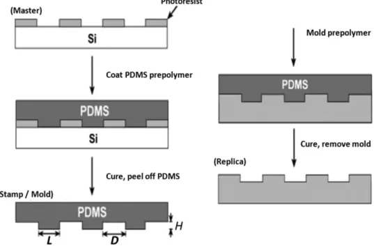
Micro-lenses and micro-lens arrays are assuming an increasingly important role in optical devices and communication systems. They become key components of many optical devices, being useful for the imaging of very small structures. In response to their extended use in different fields of technology, a great emphasis is being placed on research into simple manufacturing approaches for these micro-optical components as well as on the characterization of their performance. Currently, in industrial applications, micro-lenses are used in a large range of fields, like laser printers1 or communication systems2, and can also be useful in the fabrication of electronic devices3, such as three-dimensional (3-D) displays4, optical data storage5, solar cells6, photodetectors7, and for biological components. Numerous classes of micro-lenses exist, depending on the embedding technology and the specific applications8. An interesting property of micro-lenses consists of the possibility of tuning their focal length. In fact, many procedures have been applied for the assembly of arrayed tunable micro-lenses with a variety of materials7. The geometrical properties and the focal length of the lens array are easily modulated by controlling appropriate experimental parameters. In a general way, micro-lenses with variable focal length can be generated by actuation of liquid crystals or other liquids through electro-wetting (EW), electrophoresis, or hydrodynamic pressure7. However, in recent years, there is great interest in obtaining micro-lenses made of polymeric material, which makes their use very comfortable. In fact, polymer properties allow easy manipulation of the material, making it possible to use a large range of techniques for the fabrication of optical micro-lenses. Several techniques have been developed to make micro-lenses, using many materials and trying to keep production costs low, in order to support their spread and improve their properties. It is possible to realize structures of variable dimensions, from millimeters to micrometers. Some of these techniques are included in the soft lithography approach, based on the use of soft materials (polymers) to realize patterns of lenses on an opportune substrate (generally made of another soft material). Through soft lithography, it is possible to realize micro- and nano-structures with great precision. For example, the steps required to obtain a polydimethylsiloxane (PDMS, (C2H6OSi)n) stamp starting from a silicon
21
Figure 2.1. Steps to realize a PDMS stamp starting from a Si substrate2.
First of all, the pattern transfer consists of the fabrication of a patterned master, through a deposition of a photoresist layer on a substrate. Once the pattern master is obtained, a pre-polymer is poured on the master, then molded to generate the stamp; therefore, it is made of the pre-polymer, which becomes rigid when it cures9. Other techniques based on the use of polymers are contact printing10-11, replica molding12-13, and imprinting (embossing)14-15. Keeping a suitable contact between the substrate and the mold, contact printing became an efficient and simple method for pattern transfer16. In fact, once the stamp is made, it is possible to create more samples that follow the pattern. Other advantages of this technique are the possibility to make an additive process, with a low waste of material and to design a pattern with a large area. Contact printing is particularly indicated for two-dimensional (2-D) structures10. Regarding micro-lenses, this technique is particularly adopted for the realization of the mold that is used for the stamp of the lenses12. Replica molding10,12-13 is so called because it is able to replicate one or more characteristics of the master, also in the case of 3-D structures in a nanometer resolution. Physics parameters that regulate the accuracy of a replica are wetting, Van Der Waals forces, and kinetic factors, like the filling of the mold10. Embossing is a technique that uses thermoplastic materials and imprints micro-structures in them. This technique has great potential to make features as small as 25 nm in silicon14. Some examples of this kind of fabrication are hot embossing15, extrusion rolling embossing17, gas-assisted ultraviolet (UV) embossing18 and electromagnetic force-assisted UV imprinting19; all these works
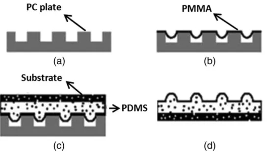
22 demonstrate that embossing is a good way to fabricate micro-lenses. Nevertheless, some of the methods described are expensive or require the use of clean-room facilities, reducing the selection of suitable materials7. Among these techniques, replica molding is probably the best: using a cured PDMS stamp and, eventually, a substrate, the polymer in liquid form is deposited over the stamp and acquires the shape of the negative of the mold. The great advantage is related to the mold: if it is suitably opportunely fabricated and dimensioned, an array of micro-lenses can be built with a single molding. An example is shown in Fig. 2.2 and consists of the fabrication of lenses using a polycarbonate (PC) substrate and a poly-metylmethacrylate (PMMA) solution deposited in the PDMS mold12. Starting from a PC substrate [Fig. 2.2(a)], a PMMA film is spin-coated on it, as shown in Fig. 2.2(b). Once the PMMA is cured, the PDMS is cast onto the PMMA film and another substrate (glass or plastic) is used to cover the system, as shown in Fig. 2.2(c). Once the PDMS is also cured, it can be easily stripped from the PMMA, allowing the micro-lens array12 to be obtained, as shown in Fig. 2.2(d).
Figure 2.2. Fabrication of micro-lenses using a PC substrate (a) coated by a first
layer of PMMA (b) and a second one of PDMS (c) in order to create a mold of micro-lenses (d)12.
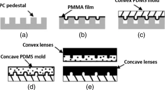
The lenses obtained, following the profile of the mold, can be defined as convex, but it is also possible to design lenses through a different mold profile to create a concave array14, as shown in Fig. 2.3.
23
Figure 2.3. Fabrication of PMMA micro-lenses using a PDMS convex (c) and
concave (d) mold, starting from a PC substrate14.
Another option to make micro-lenses is through a replica molding that uses capillaries (also called micro-molding in capillaries). It exploits the viscoelastic properties of a polymer solution that, placed in a set of channels shaped from the PDMS mold, through capillary forces, can slide into the channels and acquire the shape marked by the mold10,20. Otherwise, micro-transfer molding exploits a system where the PDMS mold is in contact with a substrate and the pre-polymer is deposited between them: micro-lenses are obtained by eventually removing the excess polymer and heating the system to cure the polymer21.
2.1.2 Electric field based techniques
Very recently, various techniques have been presented and tested for the fabrication of micro-lenses. These techniques exploit electric fields and are focused on two phenomena: EW15 and EHD22-26. EW is based on the study of the contact angle between a liquid and a substrate when an external electric field is applied27. The phenomenon can be also described through the interaction between two immiscible liquids and their behavior related to the forces applied by electric fields. The dynamic conditions of the system allow the evolution and the interaction between the liquids to be controlled, in turn controlling the meniscus’ shape, forming lenses28 and tuning their optical properties29. In fact, one of the biggest advantages of micro-lenses is the possibility to change the focus, modifying their shape by simply intervening on the radius of curvature30-31. An application of EW for the fabrication of micro-lenses is through the use of polymers that are reactive to UV rays32. The EHD, which has been already
24 discussed in Chapter 1, includes all the interactions between two electrodes and a dielectric fluid placed between them that are due to an electric field generated by the two electrodes. The nature of the material allows manipulation by the action of the electric field; a non-uniform electric field applied on a dielectric particle generates the di-electro-phoretic (DEP) effect, and it is possible to fabricate micro-lenses through this phenomenon33-35. It is also possible to fabricate micro-lenses combining a soft lithography technique with EHD: e.g., through hot embossing to generate a polymer micro-pillar array and successive EHD reflowing to create a bifocal micro-lens array23. In this category, some systems based on ink-jet printing can be included (see Sections 2.2 and 2.3). A chance to use the electric fields is based on the use of pyro-electrical materials that show an electric answer under a thermic gradient and vice versa through EW36-38 or exploiting EHD24. In particular, the combination between pyro-electric effect and EHD will be treated in the following and constitutes the center of this work. The attention will be mainly focused on an ink-jet printing approach, based on an on-demand printing of lenses with high resolution, and, on the other hand, on polymer molding and self-assembling for micro-lens arrays.
2.2 Pyro-Ink-Jet printing of micro-lenses
2.2.1 Ink-Jet printing: overview
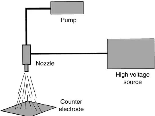
An ink-jet printer makes use of tiny ink droplets to facilitate direct printing without the device coming into contact with the printed surface. Because of this technology enables non-contact printing, it can be applied to all kinds of materials25-26,40-41 and it is now being introduced for use in a wide range of fields ranging from general purpose to industrial. Ink-jet printing has arisen from Rayleigh’s idea, but only in 1951 this method was more widely adopted39
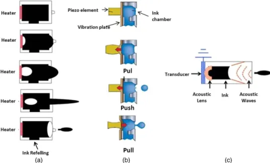
. Ink-jet printing is divided into two categories: continuous and drop-on-demand. In particular, drop-on-demand could be activated through thermal [Fig. 2.4(a)], piezoelectric [Fig. 2.4(b)], acoustic [Fig. 2.4(c)], electrostatic [for instance, EHD (as depicted in Fig. 2.5)], and, very recently, pyro-EHD effects.
25
Figure 2.4. Drop-on-demand thermal ink-jet printer (a); piezo ink-jet printing
system (b); acoustic printing (c)39.
Figure 2.5. EHD ink-jet printer (single or multi-head).
The development of the thermal ink-jet printer was inspired by the natural process of water boiling to form water bubbles39-41. In this technology, the ink in a suitable chamber is rapidly heated to a high temperature to vaporize. The vaporization promptly creates a bubble at the surface of a heater (resistor),
26 causing a pressure pulse to push the ink droplets out through the nozzle. As the ink droplets are ejected, the vapor bubble collapses, which generates a force to refill the ink39-40. The piezoelectric ink-jet exploits the inverse piezoelectric effect to work. The piezo-ceramic plate deforms in response to an electric impulse. This generates a pressure wave that causes the ink to be ejected from the nozzle. On the removal of the electric pulse, the ink is refilled as the piezo-ceramic plate returns to its normal shape39. In the acoustic printing, high-intensity sound beams can be used for ejecting droplets from a free liquid surface. This process is capable of producing drops as small as a few microns without the need for nozzles. A burst of acoustic energy focused to a diffraction-limited spot at a liquid surface can result in droplet ejection from the surface. This printer is made up of a piezoelectric transducer, an acoustic lens, and ink. When the piezoelectric transducer is excited, it makes sound waves toward the ink surface via an acoustic lens. The impact of the sound burst will cause a mound of liquid to rise from the surface due to the radiation pressure of the acoustic waves. If the energy of the incident sound beam is high enough, Rayleigh-Taylor instability will cause the top of the mound to neck down until a droplet breaks free. The droplet is expelled away from the surface at a velocity of several meters per second. After ejection, the surface relaxes as capillary waves generated near the mound propagate radially outward. Ejection droplets have been found to be very stable in size, velocity and directionality42. Moreover, between the techniques proposed, the setup used in the EHD printing method shown in Fig. 2.5 furnishes a flexible way to handle liquid and polymeric material on the micrometer and nanometer scale. This method allows manipulation of the liquid and polymeric materials by a non-uniform electric field43-47. In an electric field, an electric charge is induced on the surface of the meniscus of the ink and electrical stress stretches the meniscus toward the direction of the field, drawing the meniscus of the liquid into a sharp cone from which charged liquid droplets are ejected when the electrostatic force exceeds the surface tension40,43,46,48-49. Between the types of EHD printing systems, there is also the EHD droplet ejection, based on the spray phenomenon. The EHD spray phenomenon (known as electrospray), shown in Fig. 2.6, is mainly focused on the liquid atomization mode.
27
Figure 2.6. EHD spray phenomenon.
However, each of these techniques offers advantages and disadvantages. For example, thermal ink-jet printers are a low-cost option for printing at a fast speed with a high-quality finish. They can print on a wide variety of surfaces, including regular and specialty papers, plastics, metals and cartons. Most of these printers are simple to use and require no training or practice. But, in industrial applications, there are many problems with the high operation temperature. The thermal bubble, for instance, can be inclined to problems from the high operation temperature. As an alternative to thermal ink-jet printer, currently, the common use is a piezoelectric ink-jet printer. The piezoelectric print head, however, cannot vary the size of droplets produced by a single nozzle; there is also a limit in terms of the nozzle dimensions for high-resolution patterns, as the size of the droplet is proportional to the size of the nozzle39-40. Furthermore, reducing the nozzle size to create micro-droplets requires a reduction in the size of the piezoelectric device, leaving it unable to create sufficient force to eject the droplets. Moreover, there are many limitations related to the use of the ink because the pressure caused from the vibration of the piezoelectric device is insufficient to eject highly viscous ink40 and the cost of the piezoelectric print head and of the associated software (that directs the head to apply certain droplets of ink per dot) is considerable39. EHD ink-jet printing is, instead, a one-direct printing technology that overcomes the drawbacks of conventional piezoelectric ink-jet printing, which includes the use of highly viscous ink and nozzle-clogging
28 problems. The most attractive advantage is that EHD printing technology generates a droplet much smaller than the nozzle size so that high-resolution printing is possible25,44.
2.2.2 Pyro-EHD printing
2.2.2.1
Pyro-EHD printing working principle
As already said, the EHD printing system requires a high voltage supplier and exploits a non-uniform electric field to move a liquid or polymer material from the nozzle to the target substrate43,45,47. This configuration involves the choice of a low viscous liquid (to not obstruct the nozzle) and restricts the distance between the electrode and the counter electrode (about hundreds of microns), in order to achieve high accuracy46. The closest consequence is the limitation in placing a substrate between the nozzle and the electrode, making very difficult the direct printing on devices having millimetric thickness (such as commercial microfluidic channels). In order to evolve the system, the research has moved toward the overcoming of the nozzle limitations50. Pyro-EHD printing is a technique which does not employ nozzle, exploiting a liquid drop reservoir which is deformed, due to EHD effect, activated by a pyroelectric field8,26,51. More specifically, local pyroelectric forces, activated by scanning a thermal source over an LN substrate, draw liquid droplets from the reservoir and deposit them on a target substrate26. Moreover, this process does not require complicated electrodes or a high-voltage circuit to work and allows to use polymers having a wide range of viscosity. This method is a simple way to draw attolitre liquid droplets with high spatial resolution. One of the materials that could be used for the activation of the EHD effect is the pyroelectric LN. In general, the experimental setup of EHD printing is made up of three elements, essentially: a starting drop, a substrate that intercepts the dispensed drops on demand and a source of electric field. As shown in Fig. 2.7(b), the system is simplified with respect to the conventional ink-jet apparatus [Fig. 2.7(a)] and could be mounted in a dynamic [Fig. 2.7(c)] or static [Fig. 2.7(d)] configuration.
29
Figure 2.7. Generic setup (a); pyro-EHD setup (b); dynamic configuration (c);
static configuration (d).
In both cases, the upper plate is constituted, e.g., of a microscope coverslip used as receiving substrate, placed on a three-axis translation stage, while the LN crystal drives the process. In the static configuration, the collector is fixed in space so that the reservoir drop can dispense multiple jetting in the same position, increasing the dimension in terms of volume and the geometric characteristics of the deposited droplet. On the other hand, a more interesting configuration is related to the continuous printing of separate droplets controlling the movement of the target substrate with high-precision motorized positioners. The distance between the two plates is set on the scale of hundreds of microns depending on the investigated base drop8,26,51-52. It is well known that for a fixed drop volume, a critical value DC can be defined for the distance D between the base and the
substrate, according to the following expression: 𝐷𝐶 = (1 +𝜗4) 𝑉
1
3 (21)
where 𝜗 is the contact angle and V is the volume of the drop reservoir. A stable liquid bridge is established when D < DC. The most relevant case here refers to D
> DC, when an unstable liquid streaming regime occurs. We use such an
instability to break up the liquid reservoir and to dispense droplets8,26. A video camera is used to monitor the printing process; the light coming from a collimated LED light source (Thorlabs M470L2) illuminates the cross-section of the dispensing system, thus is collected by a 10× microscope objective and, finally, projected onto a CMOS camera (Motion ProY3-S1).
30
2.2.2.2
Micro-lenses fabrication through pyro-ink-jet printing
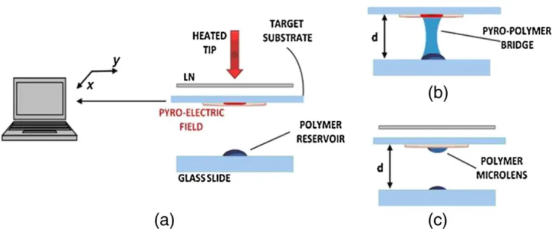
The fabrication of micro-lenses with pyro-EHD could be accomplished in various ways: by the spontaneous breakdown of an unstable matter bridge created through the pyro-EHD effect8; with a dispensing process26,52. The spontaneous breakdown of an unstable polymer bridge can be explained in this way: for a fixed volume drop [Fig. 2.8(a)], when the stable liquid bridge is formed [Fig. 2.8(b)], it is possible to separate the plates at a certain distance and obtain the micro-lenses, as shown in Fig. 2.8(c).
Figure 2.8. Scheme of the printing system (a) consisting of a LN plate, a heat
source, and a drop reservoir, formation of the pyro-polymer bridge of the polymer micro-lens (b) and the translating target substrate (c)8.
As disclosed, if the distance d > DC, it is possible to create lenses by the
dispensing process. A pointwise thermal stimulus is applied to the LN crystal to induce the pyro-electric effect locally. At equilibrium, spontaneous polarization PS of the LN crystal is fully compensated by the external screening charge and no
electric field exists. The electric field exerts an attractive force on the liquid and, when sufficiently strong, deforms the liquid into a conical tip from which a thin liquid jet is released26,51. This liquid jet is intercepted by a target substrate (Fig. 2.9), and micro-lenses are generated.
31
Figure 2.9. Dispensing nano-liter droplets for liquid patterning (a): liquid is
dispensed onto a translating substrate inserted between the LN and the glass plate. Side view of the typical printing functionality (b)26.
2.2.2.3
LN stimulation by CB-layer
A chance to extend the electric field area is the use of a carbon black (CB) layer; in fact, this layer allows one to obtain a uniform heating upon the LN crystal. The use of a CB-layer reduces the recombination of the temporary surface charges and decreases the heat transfer from the crystal to the air, thus increasing the temperature gradient and improving the pyroelectric efficiency52. The fabrication process used to produce a nano-composite coating to be applied on the surface of LN crystals is shown in Fig. 2.10.
32
Figure 2.10. Schematic diagram of the CB deposition process51.
The method consists of the preparation of a PDMS/CB film on polyvinyl alcohol (PVA)-coated glass substrate, followed by its peeling from the substrate and by the subsequent application of the resulting PDMS/CB membrane directly at a later stage to the crystal. In detail, the glass substrate, a microscope coverslip, is functionalized by spin-coating a PVA solution (2.8% in water) at 2000 rpm for 2 min. This step is repeated four times to produce a film thick enough to allow the easy peeling of the membrane [Fig. 2.10(a)]. Then, a CB suspension is prepared in PDMS [Fig. 2.10(b)] by adding 0.02 g of CB (graphitized CB-carbon nano-powder, size <200 nm, >99.95%) in 0.5 g of PDMS curing agent (Dow Corning Sylgard 184; 10:1 pre-polymer to curing agent) and sonicating it for 2 h. A drop of the suspension obtained after adding the elastomeric base to the solution is finally deposited on the top of the PVA-coated coverslip and cured at room temperature for 12 h. Once the CB membrane is peeled off the coverslip [Fig. 2.10(c)], it is set down on the crystal [Fig. 2.10(d)]. An illustration of the setup integrated with the CB-layer is reported in Fig. 2.11.
33
Figure 2.11. Pyro-EHD setup using the halogen lamp as the heating source52.
Depending on the material of the starting reservoir drop, the dynamic and jetting evolution could be different. The geometry of electric field lines, as shown in Fig. 2.12, plays a fundamental role in the process: the plots of electric field lines for localized heating and for uniform heating with a CB-layer are shown in Fig. 2.12(a) and 2.12(b), respectively.
Figure 2.12. Images of the PDMS-based reservoir drop deformation obtained by
standard pyro-effect configuration (a) and innovative pyro-effect configuration employing a CB coating (b). In case (a), the starting polymer drop assumes the shape of a liquid bridge and experiences both normal and tangential components
of the stress tensor while introducing a CB coating; (b) the pyro-effect is enhanced so that the polymer drop deforms into a sharp and elongated printing
cone under the action of the tangential components52.
It can be noted that when a CB layer is used, the electric field is very uniform over a large area, thus affecting the geometry of the dispensing process. The
34 thickness of the CB-layer is about 200 μm; this value is the result of an easy method of preparation and peeling of a uniform CB membrane balanced with the radiation absorption value for the activation of the pyroelectric effect. As explained in Chapter 1, the EHD force generated at the air-polymer interface can be represented by a stress tensor, with normal and tangential components. In Fig. 2.12(a), under the influence of the pyroelectric field, the air-polymer interface moves dynamically, while in the case of Fig. 2.12(b) it appears uniform and experiences a stress tensor with a single component. In this case, once the pyroelectric field is applied, the top polymer surface moves progressively upward with a spatially non-uniform geometry; the elongated cone experiences a greater EHD force over a small distance, thus leading to the activation of the upper surface and to the formation of a thin polymer tip. The electric field generated by the LN crystal is able to exert hydrodynamic pressure on the reservoir liquid, leading to the formation of a bridge or a conical tip that is a similar to the Taylor’s cone26,53
. The materials tested and used to make micro-lenses are PMMA and PDMS with different viscosities (PDMS: 3500 cps, PMMA: 560 cps). 200 mg/mL of PMMA (MW = 120000 amu) are dissolved in
N-Methyl-2-pyrrolidone (NMP), while PDMS is used without any additional solvents. PMMA and PDMS are chosen for their good optical and mechanical properties and the lenses are fabricated onto a highly hydrophobic substrate made from a tetraethyl orthosilicate 1H,1H,2H,2H-perfluorodecyltriethoxysilane (TEOS/PFTEOS) film, deposited on a glass substrate. The substrate is prepared as described in the following procedure: a commercial glass (Corning Eagle 2000) is used as the substrate and cleaned by a standard procedure, applying in sequence sonication with detergent in boiling water for 2 h, acetone and isopropyl alcohol and drying under nitrogen flow. A sol-gel solution is prepared by mixing TEOS, PFTEOS, ethanol, deionized water, and concentrated hydrochloric acid (HCl). Before deposition, this solution is diluted with fluoro-propanol and then filtered. The use of fluoro-propanol is aimed at enhancing the wetting of the solution-substrate system so as to improve adhesion. The solution prepared is spin-coated (1000 rpm for 30 s) by means of a Brewer Science Model 100 spin-coater, successively baked on a hot plate at 100°C for 30 min to remove residual solvent and gradually heated from 110°C to 150°C for thermal curing. Finally, the film is kept in an oven at 150°C for one night. The thickness of the TEOS/PFTEOS film is 280 nm and the contact angle exceeded 100 deg54. Once the lenses are fabricated on the target of interest, the substrate is placed onto a hot plate at 100°C for 15 min and at 150°C for 15 min, thus inducing rapid heating of the
35 sample. The subsequent sudden cooling solidifies the PDMS lenses that are therefore ready for being characterized55.
2.2.3 Forward Pyro-EHD printing configuration
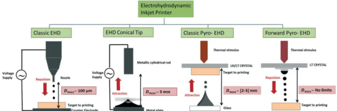
The flexibility of EHD printing systems is one of the principal turning points in the research on this field. Pyro-ink-jet printing overcomes some limitations, as reported in Section 2.2.2.1. However, the geometrical configuration of pyro-ink-jet printer constrains to put the target substrate between the drop reservoir and the pyroelectric crystal. This necessity is the same in classical EHD printing configuration, wherein the target substrate is placed between the nozzle and an electrode. That causes limitations in terms of geometrical characteristics of the target substrate, making more complex the direct dispensing or the functionalization of devices. Laser-induced forward transfer (LIFT) offers a good solution, but the system is very complex56-57. Forward pyro-ink-jet printing configuration works by placing the reservoir drop in contact with the pyroelectric crystal and the dispensing exploits the repulsive forces generated by the interaction between the liquid surface charge accumulation and the electric field58. In Fig 2.13 is showed the evolution of the EHD printer setup, from the classic EHD printer, to EHD conical tip dispenser, classic pyro-EHD printer configuration and forward pyro-EHD printer.
Figure 2.13. EHD ink-jet printers: evolution of the setup. Classic EHD setup has
nozzle and electrodes; these limitations are progressively overcome with pyro-EHD printers.
In this way, with forward pyro-EHD dispenser, the limit imposed by the target substrate thickness is completely overcome (Fig. 2.13). This setup allows the printing of liquid shots with high resolution, independently by the distance between the starting drop and the receiving substrate. The dispensing quality is also independent from the chemical nature of the substrate and the kind of material chosen for printing. In the next section, a published paper based on the
36 forward pyro-EHD technique is reported. Printed micro-structures realization and characterization is showed and, moreover, the flexibility of the setup is demonstrated, functionalizing a commercial micro-fluidic device.
37
2.3 Paper: “Direct Fabrication of Polymer
Micro-lens Array”
Authors and affiliations
Sara Coppolaa, Vito Pagliaruloa, Veronica Vespinia, Giuseppe Nastia, Federico Olivieria,b, Simonetta Grillia and Pietro Ferraroa
a
Institute of Applied Sciences and Intelligent System- CNR, Via Campi Flegrei 34, Pozzuoli (NA), 80078, Italy.
b
University of Naples Federico II, Department of Chemical Materials and Production Engineering, Piazzale Tecchio 80, Naples 80125, Italy.
Conference SPIE Optical Metrology 2017
38
2.3.1 Abstract
In order to break the rigidity of classic lithographic techniques, a flexible pyro-EHD ink-jet printing is presented. In particular, here is showed a method able to manipulate highly viscous polymers, usable for optical integrated devices. The system proposed reaches spatial resolution up to the nano-scale and can print, for instance, nano-particles and high viscous polymer solutions. This technique allows writing patterns directly onto a substrate of interest in 2D or in 3D configuration and is studied in order to overcome limitations in terms of type of materials, geometry and thickness of the substrate. In the present work, we show the potential of pyro-EHD printing in fields as optics and micro-fluidics. A micro-channel chip is functionalized with a PDMS-made micro-lenses array, directly printed on the chip. The geometric properties and the quality of the lenses are evaluated by a Digital Holography (DH) analysis.
2.3.2 Introduction
Polymer-made micro-structures are useful for a large number of applications ranging from the integral imaging for 3D displays and optical communication, to OLEDs and high-resolution imaging13,59. A great variety of techniques answers to the necessity to manufacture these micro-optical components and to characterize their performances. Between them, as already said, there are hot embossing, soft replica molding, rapid laser-based patterning, ink-jet printing, and UV-nanoimprint lithography. Anyway, some of these methods have limitations: they could be expensive, require the use of clean-room facilities or highly trained staff with a limited selection of suitable materials. One of the most used structures in optical applications are micro-lenses13,59. A micro-lenses property that raises enormous interest would be the tunability of their focal length54. Therefore, in order to varying geometric and optical characteristics of the micro-lenses, such as their tunability, many procedures have been developed. For instance, swellable polymer micro-lenses, upon exposure to solvents, create a tunable range of focal lengths, or also the generation of micro-lenses by virtue of the photo-polymerization, wherein the employment of a surfactant has broadened the range of substrates for the micro-lens formation. Recently, exploiting EHD phenomenon to manipulate polymeric solutions, new direct methods have been proposed for the micro-lenses arrays fabrication8,26,60. Here, we present a simple multiscale process able to fabricate micro-lenses arrays, using the pyro-electric effect activated onto a Lithium Niobate (LN) crystal and high viscous polymer
39 materials58. Specifically, this method is driven by the pyro-electric field, activing the EHD pressure through the application of a temperature gradient. This technique, known as pyro-EHD inkjet printing, guarantees high resolution in terms of microns, representing a competitor with conventional soft lithography techniques. Micro-lenses produced here have a diameter dimension in a range between 25 and 500 μm and have high degree of uniformity. Additionally, pyro-EHD printing allows to write directly onto a substrate of interest. In this work, a micro-lenses array has been printed and characterized onto a micro-fluidic chip. In particular, the micro-lenses optical behavior is studied in terms of the optical aberrations, intrinsically present in a lens as an optical tool, by digital holographic microscopy (DHM).
2.3.3 Pyro-EHD printing: setup evolution
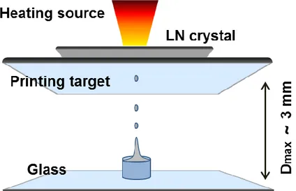
In Chapter 1 it has been explained that pyro-electricity is the property of certain materials to generate an electric potential onto their surfaces26,50,61. In this work, a LN (zcut and 500μm thick) crystal is used and a thermal stimulus produces a pyro-electric field onto its surfaces. In LN this effect is due to the movement of the lithium and niobium ions relative to the oxygen layers62-63. Furthermore, if that field is quite strong, it can generate forces able to induce an instability into fluids and polymer films64-65. Recently, we developed a pyro-EHD printing system free from nozzles and electrodes based on pyro-electric effect64. In Fig. 2.14 is represented the set-up realized for classic pyro-EHD printing.
Figure 2.14. Classic Pyro-EHD setup configuration where the maximum distance
40 There are three macro-systems composing that setup: a heating system, a moving stage system and a monitoring system. The heating source is in contact with an auxiliary plate of LN wafer. The liquid reservoir is arranged on a glass substrate in front of a second glass substrate, representing the receiver-substrate mounted onto a three axes translation stage, in contact with the LN crystal and on the same line of the heating source. The moving stage system is made up of a high precision linear motor, with an X-Y axis (SGSP26-100(XY) SIGMA KOKI CO., LTD.) and a digital motion controller (SIGMA KOKI CO., LTD.). Through this system, a speed of 30 mm/s is achievable. The monitoring system consists of a highly-sensitive and fast camera (uEye, USB 3.0, a resolution of 2048 x 2048 pixels), an optical zoom lens and a blue LED light source (Thorlabs M470L3, wavelength of 470 nm and beam power of about 650 mW). This last system is used in order to monitor the cone-jet mode and jetting status. The major limitation of this configuration was the restriction of the distance between the droplet and the LN crystal: liquid reservoir could not be so far from the crystal, i.e. the pyro-electric field. Inducing a consequent limitation on thicknesses and geometric constrain of the receiving substrate. The problem of the distance is exceeded in the novel configuration proposed in this paper: the novelty consists in the placement of the receiving substrate now in front of the drop reservoir and of the crystal (Fig. 2.15).
Figure 2.15. Novel Forward Pyro-EHD configuration where the maximum
distance is limitless.
Comparing Fig. 2.14 and Fig. 2.15, is clear that the difference between the two configurations is in the placement of the liquid reservoir that is now in contact or in proximity of the LN. The receiver-substrate is in front of the liquid reservoir