475 THE BALTIC JOURNAL OF ROAD AND BRIDGE ENGINEERING 20 1 8/13 (4) ISSN 1822-427X/eISSN 1822-4288 2018 Volume 13 Issue 4: 475–499 https://doi.org/10.7250/bjrbe.2018-13.429
* Corresponding author. E-mail: [email protected] Copyright © 2018 The Author(s). Published by RTU Press
This is an Open Access article distributed under the terms of the Creative Commons Attribution License (http://creativecommons.org/licenses/by/4.0/), which permits unrestricted use, distribution, and reproduction in any medium, provided the original author and source are credited.
LCC-BASED APPRAISAL OF BALLASTED
AND SLAB TRACKS: LIMITS AND POTENTIAL
FILIPPO GIAMMARIA PRATICO1, MARINELLA GIUNTA2*
1Dept of Information Engineering, of Infrastructures, and Sustainable Energy 2Dept of Civil, Energy, Environmental and Material Engineering University Mediterranea of Reggio Calabria, Reggio Calabria, Italy
Received 4 January 2018; accepted 21 October 2018
Abstract. The increase in train speed and axle load is an important goal to
achieve in the future. From a technical standpoint, ballastless tracks seem to be suitable to the aim, especially when high-speed passenger trains share the track with freight trains. Based on the above, the primary objective of this study is the comparison between ballasted and slab tracks regarding total costs over the life course. A suitable model to evaluate the total costs of competing solutions is set up. A solution for solving the issue of CO2 price fluctuation and
for the quantification of External Costs is also formulated. Life Cycle Costs are estimated based on agency, environmental and present user values. Analyses and results show that when Life Cycle Costing-based approaches are applied: i) Agency Costs have to be considered in the long-term perspective; ii) expected life has an appreciable impact and several solutions and systems, more affordable in the short term, yield unfavourable maintenance and renewal processes; iii) if total costs are considered over track life, the breakeven point is very far from the construction. Furthermore, the differences between the total Present Values of the two solutions become too small to yield sound conclusions in favour of the ballasted vs. the ballastless solution.
Keywords: ballasted track (BT), high-speed rail, Life Cycle Costing (LCC), slab
476 THE BALTIC JOURNAL OF ROAD AND BRIDGE ENGINEERING 20 1 8/13 (4)
Introduction
According to the SHIFT2RAIL Strategic Master Plan 2015, rising traffic demand, congestion, security of energy supply, and climate change are some of the significant issues, which Europe and the full world are trying to face. Tackling these challenges and issues requires that the railway sector takes on a larger share of transport demand in the next few decades. To this aim, transportation infrastructures are required to be more reliable and resilient, to satisfy the growing mobility necessities efficiently, to reduce environmental impact (carbon footprint), to maintain and upgrade deteriorating infrastructures (renewal processes), and to apply innovative track design and materials. For railway infrastructures, the increase of train speed and axle load calls for a better structural and geometrical stability of the track. The ballastless slab tracks (STs) seem to meet these requirements (Bilow & Randich, 2000; Gautier, 2015; Pichler & Fenske, 2013).
Non-ballasted track concept builds on the substitution of sleepers on ballast with concrete slabs on a supporting layer. Concrete slabs contain reinforcement in the neutral axis or at the top and the bottom of the slab. In the first case, reinforcement controls crack width in the concrete when the supporting layer has a substantial bearing stiffness. The second case refers to bending stresses and axial forces, especially in case of soils where some settlements are expected. This system represents the typical solution for bridges and tunnels, due to the rigid support provided by slabs, and for light rail transit (LRT) systems. Various types of ballastless track systems are in service around the world. The most popular ballastless systems are the following: Shinkansen, Rheda, Sonneville-LVT, Züblin, Stedef and Infundo-Edilon. In Italy, a system, similar to Shinkansen, was developed by IPA International Railway System Technology and applied to about 100 km of high-speed railway. Slab track systems show many advantages compared to traditional ballasted tracks (BT), such as:
1) low maintenance and higher availability;
2) low maintenance cost, approximately 20−30% less than BT; 3) increased service life (50–60 years);
4) higher lateral stability;
5) reduction of weight and height of the track;
6) more comfortable and more economic vegetation control (Darr & Fiebig, 2006; Esveld, 2001).
477 Filippo Giammaria Pratico, Marinella Giunta LCC-Based Appraisal of Ballasted and Slab Tracks: Limits and Potential
1) higher construction cost;
2) higher noise radiation, mainly due to the lack of noise absorption of the ballast bed; possible mitigation measures for noise and vibration further increase the costs of the ST construction (Di Mino, Di Liberto, & Nigrelli, 2007; Di Mino, Giunta, & Di Liberto, 2009; Praticò, Vaiana, & Iuele, 2015; Xin & Gao, 2010);
3) in case of a relevant differential settlement or train derailment, since slabs are quite massive and difficult to repair/substitute, their maintainability (i.e. the probability of performing their successful repair action within a given time) results lower than the one of a BT.
Moreover, when slabs are built on subgrades, special attention must be paid to the interaction concerning bearing capacity, and massive soil improvements are often required (Esveld, 2010). Overall, STs are more expensive to construct, but the lower demand for track maintenance and the higher serviceability during the service life make economically more profitable in a long-term perspective this track system. In the pursuit of comparing the two systems above (ballasted and ballastless), a promising approach is herein proposed and applied regarding an accurate and comprehensive Life-Cycle Costing Analysis (LCCA, based on ISO 15686-5:2008). It encompasses Agency Costs, User Costs, and Externality (AC, UC, and EX, respectively). Life-Cycle Costing provides the theoretical concepts to estimate short-term and long-term costs and performance considering all costs (tangible and intangible) over the time (Esveld, 2001; Praticò & Giunta, 2018; Stalder, 2001; Zoeteman, 2001). To this end, many data are needed such as construction methods and costs, degradation models (ballast, slab, rail, sleepers), integrated planning of renewal works, grouping of components and track segments, time interval for renewal operations, and budget restrictions (Caetano & Teixeira, 2015), material and energy consumption through their life cycle (Du & Karoumi, 2014). Unfortunately, minimal literature and research studies are available to allow the implementation of LCCA for railway tracks. Several studies addressed the lifecycle-related issues for railway transport (Banar & Özdemir, 2015), railway vehicles (Jun & Kim, 2007), computer-aided applications (Ciroth, Franze, & Berlin, 2009), and environmental product declarations (Stripple & Uppenberg, 2010). Furthermore, a method for addressing synergistically EX and AC is needed. To this end, the fluctuation of environmental costs (e.g. CO2 price per ton) and the uncertainty in the quantification of
environmental impacts still make an overall quantification process challenging to set up (Luckow, Stanton, Fields, Biewald, Jackson,
478 THE BALTIC JOURNAL OF ROAD AND BRIDGE ENGINEERING 20 1 8/13 (4)
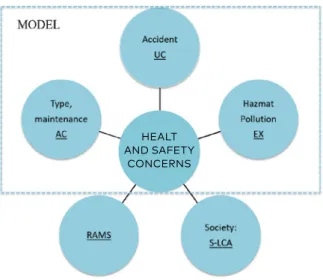
& Fisher, 2015). Another issue is railway safety that is a technical, economic, and social concern. Its relationship with LCC-type analyses is complex, and the risk of underrating or misjudging safety concerns seems quite appreciable (Praticò & Giunta, 2018). To this end, it is noted that health and safety issues are only partly considered in LCC and Life Cycle Assessment (LCA) analyses. This fact points out that more comprehensive analyses require S-LCA (cf. also ISO 14040:2006 framework; Andrews, 2010) and RAMS approaches (Calle-Cordón, Jiménez-Redondo, Morales-Gámiz, García-Villena, Garmabaki, & Odelius, 2017; Infralert, 2016; Praticò & Giunta, 2017, 2018) (Figure 1). Indeed, it is envisaged that only the consideration of society as the primary stakeholder permits achieving the proper consideration of health- and safety-related issues.
Based on the above, the main objectives of the study presented in this paper are:
1) comparing BT and ST systems regarding total costs over life; 2) highlighting potential criticalities in the application of LLC-based
methods when environmental and safety issues are considered. A long-term and synergistic perspective is considered. Life Cycle Costs are estimated based on agency, user, and environmental discounted value and a methodology to overcome uncertainty and fluctuation in environmental costs are proposed. Section 1 deals with the method and explains the innovation of the study. Section 2 focuses on results. Finally, conclusions are drawn.
Figure 1. Health and safety issues
HEALT AND SAFETY
479 Filippo Giammaria Pratico, Marinella Giunta LCC-Based Appraisal of Ballasted and Slab Tracks: Limits and Potential
1. Method
1.1. IntroductionIn the past, projects were mainly analysed based on investment costs or maintenance costs. Today the principle of Life Cycle Costing Analysis (LCCA) is strongly emerging in the railway sector (Tzanakakis, 2013; Zoeteman, 2006). ISO 15686-5:2008 defines LCC as “the cost of an asset or its parts throughout its life cycle while fulfilling the performance requirements”. Life Cycle Costing Analysis is an engineering-economic tool, which compares the relative merits of competing alternatives. Usually, environmental costs are not included in LCCA, whereas other approaches (such as the Whole-Life Costing, WLC, or Life Cycle Assessment, LCA) have a broader scope and include environmental costs. Consequently, from this perspective (which is the one followed in this paper), i.e. when including also environmental costs, minimizing the track system LCC (in terms of Present Worth Value, PWV, or PV, or in terms of Equivalent Uniform Annual Cost, EUAC) results in an increase of the sustainability of the rail superstructure (Giunta, 2016; Giunta & Praticò, 2017; Praticò & Giunta, 2016a, 2016b, 2018). The detailed analysis of the costs over the entire life cycle of the track solutions allows assessing the trend of AC (e.g. construction, inspection, maintenance and renewal), UC (e.g. time and accidents), and EX (e.g. mainly related to carbon dioxide equivalent (CO2e) emission of the competing alternatives and
recognizing the most convenient. In this section, a model to evaluate the total costs of the competing solutions, traditional rail track and ST, is set up. Tangible and intangible costs, as well as internal (e.g. AC
and UC) and EX (CO2-related) are considered. A solution for solving
the issues of CO2 price fluctuation and EX quantification is set up (see
Task 4).
1.2. Procedure
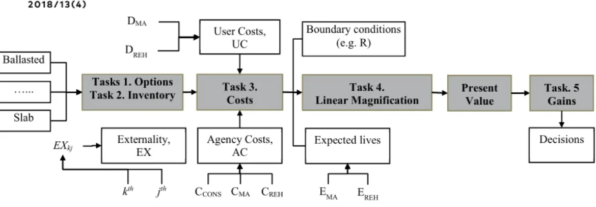
The main tasks for the application of the method (Figure 2) are the following:
1) Task 1. Design and analysis of alternatives (e.g. BT vs ST); 2) Task 2. Materials and construction-related processes inventory; 3) Task 3. Cost analysis (AC, UC, and EX);
4) Task 4. Balancing (Linear Magnification (LM) in Figure 2);
5) Task 5. Gains. In this task, each option is associated with a given sum of PVs (of the AC, UC, and EX).
480 THE BALTIC JOURNAL OF ROAD AND BRIDGE ENGINEERING 20 1 8/13 (4) 1.2. Procedure 1.2.1. Task 1
Task 1 focuses on the choice of the selected options to compare, i.e. BT and ST.
1.2.2. Task 2
Task 2 focuses on Materials and construction-related processes inventory. During this phase, all the components of the BT and ST solutions are considered. Quantities, unit costs, costs, CO2 equivalent
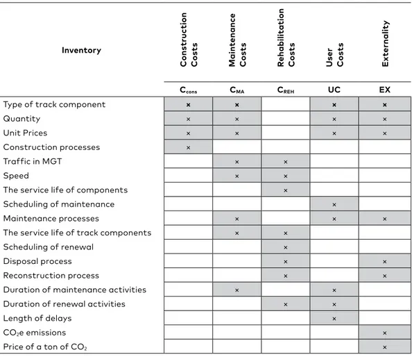
per given quantity are assessed based on the analysis of the two options described above. For example, for the BT, rails, sleepers, ballast, subballast, embankment, fastenings, baseplates, and fixings are examined. In Table 1, for each cost component highlighted in Figure 2 (e.g. construction costs), the primary data needed are detailed (e.g. track components, costs, quantities, unit prices, and construction process details).
Figure 2. Problem modelling
Note: DMA − delay-related costs for maintenance; DREH − delay-related costs for rehabilitation; EXkj − externality generated by the kth activity/processes and the jth indicator/impact; k − processes (construction, renewal, maintenance, transportation, quarrying, landfill use, material production (rails, fastenings, baseplates, sleepers/slabs, ballast/elastomer, subballast, concrete, embankment, fixings)); j − indicators CO2e, sulfur oxide (SOx), nitrogen oxides (NOx), carbon monoxide (CO), Volatile Organic Compounds (VOC), Particulate Matter (PM), noise, water quality, soil quality, biodiversity, land take, quarries, landfills, and visual effects; CCONS − construction costs; CREH, CMA (EREH, EMA) − costs (Expected lives) referred to rehabilitation (REH) or maintenance (MA); R − Rate (interest, inflation); LM − Linear Magnification; PV − Present Values; Gains, e.g.
Gi = PVBallast − PVSlab. User Costs, UC Boundary conditions (e.g. R) Task 3. Costs DMA CCONS CREH Tasks 1. Options Task 2. Inventory Ballasted CMA …... Slab Task 4.
Linear Magnification Present Value Task. 5Gains DREH Agency Costs, AC EXkj Externality, EX EREH EMA
Expected lives Decisions
481
Table 1. Input data for costs estimation
Inventory C on st ru ct ion Co st s M ai nt ena nc e Co st s R eha bi lit at ion Co st s Us er Co st s E xt ern al it y Ccons CMA CREH UC EX
Type of track component × × × ×
Quantity × × × ×
Unit Prices × × × ×
Construction processes ×
Traffic in MGT × ×
Speed × ×
The service life of components ×
Scheduling of maintenance ×
Maintenance processes × × ×
The service life of track components × ×
Scheduling of renewal ×
Disposal process × ×
Reconstruction process × ×
Duration of maintenance activities × ×
Duration of renewal activities × ×
Length of delays ×
CO2e emissions ×
Price of a ton of CO2 ×
1.2.3. Task 3
Task 3 addresses EX, UC and AC. This latter refers to the costs paid by the owner of the track (AC, cf. Figure 2, Table 1, Table 2). They include rehabilitation and maintenance activities. For rehabilitation, each component of the given option (i.e. rails) is supposed to undergo a scheduled process of rehabilitation over time. This tricky task is accomplished based on the international literature, on pieces of information gathered for tracks in service in the country, based on materials (geometry, material quality and quantity), and traffic (Andersson, Björklund, & Haraldsson, 2016). Assessing the rehabilitation frequency per given component, under given hypotheses of traffic, is a key factor in this task. The main items
482 THE BALTIC JOURNAL OF ROAD AND BRIDGE ENGINEERING 20 1 8/13 (4)
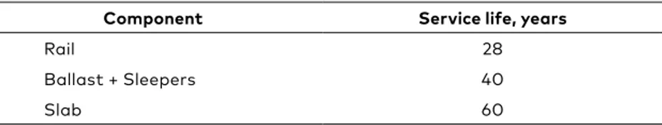
considered are rails, sleepers, and ballast/slab. Table 2 summarises the typical service lives of the components (Calvo, De Oña, López-Maldonado, Garach, & De Oña, 2013; Esveld, 2001; Milford & Allwood, 2010). In particular, the expected life of rails (e.g. 800 gross million tonnes) depends on a number of parameters. The following are listed: curve or straight track (the inside edge of the top part wears rapidly in low radius curves), rail quality, grade, axle loading and tonnage over the line, rail metallurgy, welded or jointed, maintenance (cyclical grinding), position (outer versus inner) and type of support (slab versus ties).
Rails service life is a vital issue, which interacts with user costs (accidents costs), track type, and rail type. To this end, it is worth noting that:
1) rail cost is about 20% of the overall superstructure costs for ST and more than 30% for BT (Popović, Lazarević, Brajović, & Gladović, 2014);
2) wear, rolling contact fatigue, plastic flow, defects of type 2202 (long-pitch corrugation, inner rail) and 2223 (head checking outer rail) hinder rail ability to withstand loads in safety conditions. Furthermore, jointed tracks or temporary, non-bolted joints affect operations, safety, and track service life (Klockner & Toft, 2018); 3) continuous and advanced monitoring of defects, rail-grinding
strategies (preventive, cyclic and corrective activities) is needed to limit agency and user costs.
For annual maintenance, each option is associated with a given schedule over time regarding maintenance. Typical maintenance activities are rail grinding; replacement of defective rails and sleepers, tamping, track stabilisation, ballast injection. Frequencies, costs, and methods vary, and approaches are different. Bilow & Randich (2000) and Tsoukantas & Giannakos (2008) provide the following ballpark figures, for example:
1) non-uniform BT degradation results in a higher rate of rail wear/ defects;
2) maintenance of track activities include tamping, adding ballast every 15 MGT (million gross tons per year), surfacing and alignment,
Table 2. The service life of track components
Component Service life, years
Rail 28
Ballast + Sleepers 40
483 Filippo Giammaria Pratico, Marinella Giunta LCC-Based Appraisal of Ballasted and Slab Tracks: Limits and Potential
subgrade improvement, tie replacement (60−100 sleepers per mile per year), and rail replacement (after 3−5 years on heavy haul lines); 3) Annual Maintenance Costs (AMC) of ballastless tracks usually
range from 75% to 90% than the ones for BT; maintenance activities result in a short life cycle (1−5 years) and maintenance frequencies are affected by failure patterns and repair methods adopted (mean times to restore services (MTRS) and mean time among failures (MTBF)) (Smith, 2005));
4) marginal railway track renewal costs, calculated as a change in present values of renewal costs from premature renewal following increased traffic volumes, are estimated to approximately 0.002 EUR/GTkm (Andersson, Björklund, & Haraldsson, 2016); 5) costs of maintenance activities mainly depend on speed and
traffic (Baumgartner, 2001; Silavong, Guiraud, & Brunel, 2014; Thompson, 1986); expenditures for maintenance, occurring at certain times, is distributed annually.
In this study, based on the literature and data gathered, the following Eq. (1) is set up and applied:
1986); expenditures for maintenance, occurring at certain times, is distributed annually.
In this study, based on the literature and data gathered, the following Eq. (1) is set up and applied:
AMC = a�2.21V−100200 + 4.06� ∙GTK�−0.05b V−100200 + 0.63b�, (1)
where AMC − Annual Maintenance Costs in kEUR, thousands of Euros/single track/kilometre; V − maximum speed allowed in the track, km/h; GTK − refers to gross ton-kilometres, ton·km; a and b − coefficients to calibrate.
The rationale behind Eq. (1) is very simple:
i) for a given speed, the higher the GTK, the higher the AMC; ii) for a given GTK, the higher the speed, the higher the AMC;
iii) higher speeds correspond to higher AMC and higher first derivatives. For a = b = 1, the underlying data of Eq. (1) are the ones in Baumgartner (2001). Eq. (1) allows deriving AMC for a broader spectrum of speeds and GTKs. It seems important to highlight that AMC is influenced by many other supplementary variables, such as system typology and frequency of monitoring.
Each maintenance operation corresponds to a given cost and a corresponding PV. Present Values are assessed based on the hypotheses hereafter described regarding inflation and interest rate. For the options considered, in pursuit of the estimation of AC for the given alternative, it is essential to observe that the initial construction cost is different, as well as the construction period and the costs incurred in successive rehabilitation works, and the so-called Salvage Value (Residual Value).
Based on the above, the following algorithm for the PV is set up: PVAC = CCONS + ∑ CMA REMA + ∑ CREH REREH− S, (2)
where PVAC − the Present Value of Agency Costs; CCONS − the Construction Cost; CMA − the Maintenance Cost; CREH − the Rehabilitation Cost; EREH − the expected time for rehabilitation; EMA − the expected time for maintenance; S − the salvage value; R − rate R = 1+ r1+ i, where i − the inflation rate and r − the interest rate.
Importantly:
i) the expression used above for R allows considering both the nominal interest rate (r) and the inflation rate (i);
ii) the real interest rate (rr) is expressed as a function of r and i through
the relationship R =1+i1+r = (1 + rr)−1;
iii) the expression above permits complying with real discount rates (rr)
which reflects the real-time value of money with no inflation premium;
iv) for the case under study, a real interest rate of about 3.8% (average value in 2012−2014 by Trading Economics) was used and corresponds to R = 0.963 with r = 0.08 and i = 0.04 (Table 4);
, (1) where AMC − Annual Maintenance Costs in kEUR, thousands of Euros/ single track/kilometre; V − maximum speed allowed in the track, km/h; GTK − refers to gross ton-kilometres, ton·km; a and b − coefficients to calibrate.
The rationale behind Eq. (1) is very simple:
1) for a given speed, the higher the GTK, the higher the AMC; 2) for a given GTK, the higher the speed, the higher the AMC;
3) higher speeds correspond to higher AMC and higher first derivatives.
For a = b = 1, the underlying data of Eq. (1) are the ones in Baumgartner (2001). Eq. (1) allows deriving AMC for a broader spectrum of speeds and GTKs. It seems important to highlight that AMC is influenced by many other supplementary variables, such as system typology and frequency of monitoring.
Each maintenance operation corresponds to a given cost and a corresponding PV. Present Values are assessed based on the hypotheses hereafter described regarding inflation and interest rate. For the options considered, in pursuit of the estimation of AC for the given alternative, it is essential to observe that the initial construction cost is different, as well as the construction period and the costs incurred in successive rehabilitation works, and the so-called Salvage Value (Residual Value).
484 THE BALTIC JOURNAL OF ROAD AND BRIDGE ENGINEERING 20 1 8/13 (4)
1986); expenditures for maintenance, occurring at certain times, is distributed annually.
In this study, based on the literature and data gathered, the following Eq. (1) is set up and applied:
AMC = a�2.21V−100200 + 4.06� ∙GTK�−0.05b V−100200 + 0.63b�, (1)
where AMC − Annual Maintenance Costs in kEUR, thousands of Euros/single track/kilometre; V − maximum speed allowed in the track, km/h; GTK − refers to gross ton-kilometres, ton·km; a and b − coefficients to calibrate.
The rationale behind Eq. (1) is very simple:
i) for a given speed, the higher the GTK, the higher the AMC; ii) for a given GTK, the higher the speed, the higher the AMC;
iii) higher speeds correspond to higher AMC and higher first derivatives. For a = b = 1, the underlying data of Eq. (1) are the ones in Baumgartner (2001). Eq. (1) allows deriving AMC for a broader spectrum of speeds and GTKs. It seems important to highlight that AMC is influenced by many other supplementary variables, such as system typology and frequency of monitoring.
Each maintenance operation corresponds to a given cost and a corresponding PV. Present Values are assessed based on the hypotheses hereafter described regarding inflation and interest rate. For the options considered, in pursuit of the estimation of AC for the given alternative, it is essential to observe that the initial construction cost is different, as well as the construction period and the costs incurred in successive rehabilitation works, and the so-called Salvage Value (Residual Value).
Based on the above, the following algorithm for the PV is set up: PVAC = CCONS + ∑ CMA REMA + ∑ CREH REREH− S, (2)
where PVAC − the Present Value of Agency Costs; CCONS − the Construction Cost; CMA − the Maintenance Cost; CREH − the Rehabilitation Cost; EREH − the expected time for rehabilitation; EMA − the expected time for maintenance; S − the salvage value; R − rate R = 1+ r1+ i, where i − the inflation rate and r − the interest rate.
Importantly:
i) the expression used above for R allows considering both the nominal interest rate (r) and the inflation rate (i);
ii) the real interest rate (rr) is expressed as a function of r and i through
the relationship R =1+i1+r = (1 + rr)−1;
iii) the expression above permits complying with real discount rates (rr)
which reflects the real-time value of money with no inflation premium;
iv) for the case under study, a real interest rate of about 3.8% (average value in 2012−2014 by Trading Economics) was used and corresponds to R = 0.963 with r = 0.08 and i = 0.04 (Table 4);
, (2) where PVAC − the Present Value of Agency Costs; CCONS − the Construction
Cost; CMA − the Maintenance Cost; CREH − the Rehabilitation Cost;
EREH − the expected time for rehabilitation; EMA − the expected time for
maintenance; S − the salvage value; R − rate , where i − the inflation rate and r − the interest rate.
Importantly:
1) the expression used above for R allows considering both the nominal interest rate (r) and the inflation rate (i);
2) the real interest rate (rr) is expressed as a function of r and i through the relationship
1986); expenditures for maintenance, occurring at certain times, is distributed annually.
In this study, based on the literature and data gathered, the following Eq. (1) is set up and applied:
AMC = a�2.21V−100200 + 4.06� ∙GTK�−0.05b V−100200 + 0.63b�, (1)
where AMC − Annual Maintenance Costs in kEUR, thousands of Euros/single track/kilometre; V − maximum speed allowed in the track, km/h; GTK − refers to gross ton-kilometres, ton·km; a and b − coefficients to calibrate.
The rationale behind Eq. (1) is very simple:
i) for a given speed, the higher the GTK, the higher the AMC; ii) for a given GTK, the higher the speed, the higher the AMC;
iii) higher speeds correspond to higher AMC and higher first derivatives. For a = b = 1, the underlying data of Eq. (1) are the ones in Baumgartner (2001). Eq. (1) allows deriving AMC for a broader spectrum of speeds and GTKs. It seems important to highlight that AMC is influenced by many other supplementary variables, such as system typology and frequency of monitoring.
Each maintenance operation corresponds to a given cost and a corresponding PV. Present Values are assessed based on the hypotheses hereafter described regarding inflation and interest rate. For the options considered, in pursuit of the estimation of AC for the given alternative, it is essential to observe that the initial construction cost is different, as well as the construction period and the costs incurred in successive rehabilitation works, and the so-called Salvage Value (Residual Value).
Based on the above, the following algorithm for the PV is set up: PVAC = CCONS + ∑ CMA REMA + ∑ CREH REREH− S, (2)
where PVAC − the Present Value of Agency Costs; CCONS − the Construction Cost; CMA − the Maintenance Cost; CREH − the Rehabilitation Cost; EREH − the expected time for rehabilitation; EMA − the expected time for maintenance; S − the salvage value; R − rate R = 1+ r1+ i, where i − the inflation rate and r − the interest rate.
Importantly:
i) the expression used above for R allows considering both the nominal interest rate (r) and the inflation rate (i);
ii) the real interest rate (rr) is expressed as a function of r and i through
the relationship R =1+r1+i = (1 + rr)−1;
iii) the expression above permits complying with real discount rates (rr)
which reflects the real-time value of money with no inflation premium;
iv) for the case under study, a real interest rate of about 3.8% (average value in 2012−2014 by Trading Economics) was used and corresponds to R = 0.963 with r = 0.08 and i = 0.04 (Table 4);
3) the expression above permits complying with real discount rates (rr) which reflects the real-time value of money with no inflation premium;
4) for the case under study, a real interest rate of about 3.8% (average value in 2012−2014 by Trading Economics) was used and corresponds to R = 0.963 with r = 0.08 and i = 0.04 (Table 4); 5) based on the above, in the following, analyses are focused on the
remaining aspects.
As already, mentioned, maintenance scheduling varies, and their cost is modelled as annual (AMC). When the period of analysis approaches infinity, the salvage value approaches zero, and the following Eq. (3) applies:
PVAC = CCONS + CMA REMA(1 – RD)-1 + CREHREREH(1 – RD)-1, (3)
where D − the expected life of the as-design track.
Task 3 also focuses on UC. They include delays (PVD),
vehicle-operating costs (PVVOC), and accident costs (PVA) (fatal, nonfatal,
property damages). According to Esveld (2001), the most critical feature of a decision support system, dealing with maintenance strategy, is the relationship between track use and maintenance. This fact explains the importance of UC for railways tracks. Furthermore, the same author observes that the infrastructure use determines largely:
1) the maintenance needs, i.e. as a function of traffic volume and type;
2) the impact of track failures, i.e. cumulative train delays and cancellations;
3) the slots available for maintenance.
Consequently, the estimate of user costs is a very complex task. Importantly, when the LCC breakdown is considered, increasing costs of traffic disruption is estimated to be about the tenth part of CMA and
485 Filippo Giammaria Pratico, Marinella Giunta LCC-Based Appraisal of Ballasted and Slab Tracks: Limits and Potential
User Costs, as mentioned, include PVD, originated by work zones of
given length and duration (Walls & Smith, 1998). Lovett, Dick, & Barkan (2015a), identifies two categories of delays: routine, experienced during normal operations, including crew changes, meets, passes, and local speed restrictions, and irregular, including maintenance/renewal, accidents, and short-term speed restrictions based on track conditions. This paper takes into account delays originated by maintenance and renewal activities. This category of delays depends on track type, uncertainties relate to the expected operating conditions and maintenance needs of innovative technologies (Zoeteman, 2001).
The cost of train delay per hour varies based on a variety of factors broken into five main categories: crew, cars, locomotives, and fuel and most of these costs vary with train composition (Lovett, Dick, Ruppert, & Barkan, 2015b). By literature (Dingler, Lai, & Barkan, 2011; Lai & Barkan, 2009; Lovett, Dick, & Barkan, 2015a; RSAC, 1999; Schafer & Barkan, 2008; Schlake, Barkan, & Edwards, 2011). Delay costs for railroads range from 200 EUR to more than 900 EUR per train-hour. Assuming an average train composition, then crew, car, lading, and locomotive, costs are approximately 900 EUR train-hour. Based on the above the following Eq. (4) applies:
PVUC = PVD + PVA + PVVOC = ∑CDREHREREH + ∑CDMAREMA + PVA + PVVOC, (4)
where PVUC − the Present Value of User Costs, PVD, PVA, PVVOC are the
Present Values of the cost due to delays (D), accidents (A), and vehicle operating costs (VOC), respectively; CDREH − the cost of delays due to the
rehabilitation; CDMA − the cost of delays due to the maintenance; EREH and
EMA − the expected time for rehabilitation and maintenance, respectively.
By referring to accident costs, the fatalities per billion passenger-miles are around 0.4 for trains, 7.0 for cars, and 0.1 for aeroplanes.
Externalities (Task 3) include transportation, quarrying, landfill use, material production (cement, steel, rubber) and impact construction/ renewal/maintenance activities which imply environmental concerns such as climate change (CO2e), air quality (SOx,
NOx, CO, PM), noise, water quality, soil quality, biodiversity, land take,
quarries, landfills, and visual effects.
Milford & Allwood (2010) investigated the CO2 impact of current
and future rail track systems. They observed that vehicle operations
contribute for approximately 70% of lifecycle CO2 emissions,
construction, maintenance and disposal of infrastructure for nearly 20%, and vehicle manufacturing, maintenance and disposal for the remaining 10%. Further, they found that the current track
configurations with concrete sleepers have the lowest CO2 impact,
486 THE BALTIC JOURNAL OF ROAD AND BRIDGE ENGINEERING 20 1 8/13 (4) future rail track designs potentially lead to up to a 40% reduction in CO2 impact.
Åkerman (2011) estimated that the proposed high-speed rail track in Sweden is expected in lifecycle emissions reductions for about
550,000 tons of CO2-equivalents per annum by 2025/2030, with almost
60% through a shift from truck to rail freight and 40% based on a shift from air and road travel to high-speed rail travel.
Westin & Kågeson (2012) analysed the climate implications of investments in high-speed railway lines and found that traffic volumes of more than 10 million annual one-way trips are usually required to balance the annualised emissions from the railway construction.
For production-related issues (aggregate, cement, steel), carbon dioxide is one of several heat-trapping greenhouse gases (GHGs) emitted. Based on the European Commission Report of 2010, these gas emissions are the primary cause of global warming. To this end, a carbon dioxide equivalency is usually used (amount of CO2, which has the same global
warming potential (GWP), when measured over a specified timescale, generally, 100 years). It is usually expressed in grammes of carbon
dioxide equivalents per km (god/km). For example, the CO2e figure
of cementations material is about 950 kg CO2 per tonne (Lee, Lee, &
Kim, 2008), while the CO2e figure of asphalt concrete is about 60 kg
CO2 per tonne (Zwan, 2012). The quantification of EX is carried out by
considering:
1) the quantity of CO2 equivalent corresponding to the given process
and material;
2) the price of a ton of CO2 expressed regarding Social Cost of Carbon;
3) the remaining factors associated to the process under consideration (quarrying, landfill, transportation-related emissions);
4) the algorithm set up in Eqs (5)−(7). Based on this discussion, different classes of externalities, EXkj are considered, where
j refers to the jth impact (e.g. CO2 equivalent, air quality,
noise, biodiversity), while k stands for the kth activity (e.g.
k=0 construction, EX0, kth successive rehabilitation/routine
maintenance, EXk):
EXkj = ∑j Qkj UPkj, (5)
where EXkj − the class of Externality, j − a jth impact, e.g. CO2
equivalent; k − the kth activity, e.g. construction, EX
0, successive kth
rehabilitation/ routine maintenance, EXk; Qkj − the quantity; UPkj − the unit price of the Externality.
For the estimation of CO2 emissions (transport related), the following
487 Filippo Giammaria Pratico, Marinella Giunta LCC-Based Appraisal of Ballasted and Slab Tracks: Limits and Potential EXkj = ∑ Qj kj UPkj, (5)
where EXkj − the class of Externality, j − a jth impact, e.g., CO2 equivalent; k − the kth activity, e.g., construction, EX0, successive kth rehabilitation/routine maintenance, EXk; Qkj − the quantity; UPkj − the unit price of the Externality.
For the estimation of CO2 emissions (transport related), the following Eq. (6) is used:
EXkCO2= ∑ VNkj
CAkj
j Dkj EMkj FCkj, (6)
where EX𝑘𝑘𝑘𝑘CO2 − the cost of the CO2 emissions, where k refers to the kth rehabilitation process; VNkj − the volume of material needed, m3; CAkj − the
average truck capacity, m3, Dkj − the average distance to cover (round trip), km; EMkj − an emission surcharge factor (EUR/l), FCkj − stands for fuel consumption
(l/km), j − refers to a given process-material. Finally, it results:
PVEX = EX0 + ∑ EXk k REk�1 − RD�−1, (7)
where PVEX − the Present Value of Externality; EX0 − the Externality due to the construction stage, EXk − the Externality due to the kth activity, Ek − the expected
time of the kth activity (maintenance or rehabilitation). 1.2.4. Task 4
Task 4 deals with the derivation of a sound quantification of the EX, despite the evidence of the fluctuation of the CO2 price per ton. The quantification of the CO2 emissions is a well-established practice (European Union Emissions Trading System (EU ETS) (Sijm, Neuhoff, & Chen, 2006), but the fluctuation of the carbon price is a matter of fact (Chevallier, 2012). This fact implies inconsistent decision-making processes because of a biased evaluation of alternatives against objectives (Tasks 3 and 5 in Figure 2). To this end, an indicator (ν), that refers to the most critical relationship between internal and internalised costs, is derived in Eq. (8).
ν = mini = 1, 2, kPVACi + PVUCi PVEXi . (8)
This indicator, applied to each solution, leads a Linear Magnification/Reduction of EX. In other terms, through the introduction of the abovementioned coefficient ν, the relationship between the three main classes of costs, i.e., AC, UC, and EX, is balanced.
The following procedure is herein proposed in the case of PVEXi <
PVACi + PVUCi, for each ith design alternative:
PVEX' i = ν PVEXi. (9)
, (6) where − EXkCO2 the cost of the CO2 emissions, k refers to the kth
rehabilitation process; VNkj − the volume of material needed, m3; CAkj − the average truck capacity, m3, Dkj − the average distance to cover (round
trip), km; EMkj − an emission surcharge factor (EUR/l), FCkj − stands for fuel consumption (l/km), j − refers to a given process-material.
Finally, it results:
EXkj = ∑ Qj kj UPkj, (5)
where EXkj − the class of Externality, j − a jth impact, e.g., CO2 equivalent; k − the kth activity, e.g., construction, EX0, successive kth rehabilitation/routine maintenance, EXk; Qkj − the quantity; UPkj − the unit price of the Externality.
For the estimation of CO2 emissions (transport related), the following Eq. (6) is used:
EXkCO2= ∑ VNkj
CAkj
j Dkj EMkj FCkj, (6)
where EX𝑘𝑘𝑘𝑘CO2 − the cost of the CO2 emissions, where k refers to the kth rehabilitation process; VNkj − the volume of material needed, m3; CAkj − the
average truck capacity, m3, Dkj − the average distance to cover (round trip), km; EMkj − an emission surcharge factor (EUR/l), FCkj − stands for fuel consumption
(l/km), j − refers to a given process-material. Finally, it results:
PVEX = EX0 + ∑ EXk k REk�1 − RD�−1, (7)
where PVEX − the Present Value of Externality; EX0 − the Externality due to the construction stage, EXk − the Externality due to the kth activity, Ek − the expected
time of the kth activity (maintenance or rehabilitation). 1.2.4. Task 4
Task 4 deals with the derivation of a sound quantification of the EX, despite the evidence of the fluctuation of the CO2 price per ton. The quantification of the CO2 emissions is a well-established practice (European Union Emissions Trading System (EU ETS) (Sijm, Neuhoff, & Chen, 2006), but the fluctuation of the carbon price is a matter of fact (Chevallier, 2012). This fact implies inconsistent decision-making processes because of a biased evaluation of alternatives against objectives (Tasks 3 and 5 in Figure 2). To this end, an indicator (ν), that refers to the most critical relationship between internal and internalised costs, is derived in Eq. (8).
ν = mini = 1, 2, kPVACi + PVUCi PVEXi . (8)
This indicator, applied to each solution, leads a Linear Magnification/Reduction of EX. In other terms, through the introduction of the abovementioned coefficient ν, the relationship between the three main classes of costs, i.e., AC, UC, and EX, is balanced.
The following procedure is herein proposed in the case of PVEXi <
PVACi + PVUCi, for each ith design alternative:
PVEX' i = ν PVEXi. (9)
, (7) where PVEX − the Present Value of Externality; EX0 − the Externality due
to the construction stage, EXk − the Externality due to the kth activity, Ek − the expected time of the kth activity (maintenance or rehabilitation).
1.2.4. Task 4
Task 4 deals with the derivation of a sound quantification of the EX, despite the evidence of the fluctuation of the CO2 price per ton. The
quantification of the CO2 emissions is a well-established practice (European
Union Emissions Trading System (EU ETS) (Sijm, Neuhoff, & Chen, 2006), but the fluctuation of the carbon price is a matter of fact (Chevallier, 2012). This fact implies inconsistent decision-making processes because of a biased evaluation of alternatives against objectives (Tasks 3 and 5 in Figure 2). To this end, an indicator (ν), that refers to the most critical relationship between internal and internalised costs, is derived in Eq. (8).
EXkj = ∑ Qj kj UPkj, (5)
where EXkj − the class of Externality, j − a jth impact, e.g., CO2 equivalent; k − the kth activity, e.g., construction, EX0, successive kth rehabilitation/routine maintenance, EXk; Qkj − the quantity; UPkj − the unit price of the Externality.
For the estimation of CO2 emissions (transport related), the following Eq. (6) is used:
EXkCO2= ∑ VNkj
CAkj
j Dkj EMkj FCkj, (6)
where EX𝑘𝑘𝑘𝑘CO2 − the cost of the CO2 emissions, where k refers to the kth rehabilitation process; VNkj − the volume of material needed, m3; CAkj − the
average truck capacity, m3, Dkj − the average distance to cover (round trip), km; EMkj − an emission surcharge factor (EUR/l), FCkj − stands for fuel consumption
(l/km), j − refers to a given process-material. Finally, it results:
PVEX = EX0 + ∑ EXk k REk�1 − RD�−1, (7)
where PVEX − the Present Value of Externality; EX0 − the Externality due to the construction stage, EXk − the Externality due to the kth activity, Ek − the expected
time of the kth activity (maintenance or rehabilitation). 1.2.4. Task 4
Task 4 deals with the derivation of a sound quantification of the EX, despite the evidence of the fluctuation of the CO2 price per ton. The quantification of the CO2 emissions is a well-established practice (European Union Emissions Trading System (EU ETS) (Sijm, Neuhoff, & Chen, 2006), but the fluctuation of the carbon price is a matter of fact (Chevallier, 2012). This fact implies inconsistent decision-making processes because of a biased evaluation of alternatives against objectives (Tasks 3 and 5 in Figure 2). To this end, an indicator (ν), that refers to the most critical relationship between internal and internalised costs, is derived in Eq. (8).
ν = mini = 1, 2, kPVACiPV + PVUCi EXi . (8)
This indicator, applied to each solution, leads a Linear Magnification/Reduction of EX. In other terms, through the introduction of the abovementioned coefficient ν, the relationship between the three main classes of costs, i.e., AC, UC, and EX, is balanced.
The following procedure is herein proposed in the case of PVEXi <
PVACi + PVUCi, for each ith design alternative:
PVEX' i = ν PVEXi. (9)
. (8) This indicator, applied to each solution, leads a Linear Magnification/ Reduction of EX. In other terms, through the introduction of the abovementioned coefficient ν, the relationship between the three main classes of costs, i.e. AC, UC, and EX, is balanced.
The following procedure is herein proposed in the case of PVEXi < PVACi + PVUCi, for each i-th design alternative:
EXkj = ∑ Qj kj UPkj, (5)
where EXkj − the class of Externality, j − a jth impact, e.g., CO2 equivalent; k − the kth activity, e.g., construction, EX0, successive kth rehabilitation/routine maintenance, EXk; Qkj − the quantity; UPkj − the unit price of the Externality.
For the estimation of CO2 emissions (transport related), the following Eq. (6) is used:
EXkCO2= ∑ VNkj
CAkj
j Dkj EMkj FCkj, (6)
where EX𝑘𝑘𝑘𝑘CO2 − the cost of the CO2 emissions, where k refers to the kth rehabilitation process; VNkj − the volume of material needed, m3; CAkj − the
average truck capacity, m3, Dkj − the average distance to cover (round trip), km; EMkj − an emission surcharge factor (EUR/l), FCkj − stands for fuel consumption
(l/km), j − refers to a given process-material. Finally, it results:
PVEX = EX0 + ∑ EXk k REk�1 − RD�−1, (7)
where PVEX − the Present Value of Externality; EX0 − the Externality due to the construction stage, EXk − the Externality due to the kth activity, Ek − the expected
time of the kth activity (maintenance or rehabilitation). 1.2.4. Task 4
Task 4 deals with the derivation of a sound quantification of the EX, despite the evidence of the fluctuation of the CO2 price per ton. The quantification of the CO2 emissions is a well-established practice (European Union Emissions Trading System (EU ETS) (Sijm, Neuhoff, & Chen, 2006), but the fluctuation of the carbon price is a matter of fact (Chevallier, 2012). This fact implies inconsistent decision-making processes because of a biased evaluation of alternatives against objectives (Tasks 3 and 5 in Figure 2). To this end, an indicator (ν), that refers to the most critical relationship between internal and internalised costs, is derived in Eq. (8).
ν = mini = 1, 2, kPVACi + PVUCi PVEXi . (8)
This indicator, applied to each solution, leads a Linear Magnification/Reduction of EX. In other terms, through the introduction of the abovementioned coefficient ν, the relationship between the three main classes of costs, i.e., AC, UC, and EX, is balanced.
The following procedure is herein proposed in the case of PVEXi <
PVACi + PVUCi, for each ith design alternative:
PVEX' i = ν PVEXi. (9) . (9)
Consequently, in just one case, named j, the following two Eqs (10)− (11) result:
Consequently, in just one case, named j, the following two Eqs (10)−(11) result:
PVACj+ PVUCj= ν PVEXj=PVEX′ 𝑗𝑗𝑗𝑗, (10) PVj = PVACj + PVUCj+ PVEX' j = 2PVEX' j. (11)
In pursuit of the estimation of the overall gain for each solution, it is worth noting that AC, UC and EX contribute to the overall PV as per Eq. (12):
PV = PVAC + PVUC + PVEX' . (12) 1.2.5. Task 5
In Task 5, gains (G) are derived, as per Eq. (13). Based on the abovementioned three different classes (AC, UC, and EX’), it is possible to estimate the gain originated by one solution (for example, ST) with respect to the control case (BT) with consideration of only AC (GAC) or only EX (GEX), or any other combinations as appropriate:
G = (PVAC + PVUC + PVEX)ballast− (PVAC +
PVUC + PVEX)slab=[(PVAC)ballast− (PVAC)slab] + [(PVUC)ballast−
(PVUC)slab] + ��PVEX'�ballast− �PVEX'�slab� = GAC + GUC + GEX'. (13)
Positive gains correspond to solutions better than the traditional one, i.e., BT.
2. Results
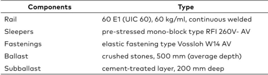
Two design alternatives, BT and ST, were considered (Tables 3 and 4). The method application was referred to a theoretical (hypothetical) stretch of 1000 m double-track, high-speed railroad. For the traditional BT, the primary engineering inputs are detailed in Table 3.
Table 3. Ballasted track components
Components Type
Rail 60 E1 (UIC 60), 60 kg/ml, continuous welded Sleepers pre-stressed mono-block type RFI 260V- AV Fastenings elastic fastening type Vossloh W14 AV Ballast crushed stones, 500 mm (average depth) Subballast cement-treated layer, 200 mm deep
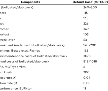
Table 4. Input data
Components Default Cost* (103 EUR)
Rails (ballasted/slab track) 240−300
Sleepers 115
Slabs 165
Ballast 226
Elastomer 369
, (10)
Consequently, in just one case, named j, the following two Eqs (10)−(11) result:
PVACj+ PVUCj= ν PVEXj=PVEX′ 𝑗𝑗𝑗𝑗, (10) PVj = PVACj + PVUCj+ PVEX' j = 2PVEX' j. (11)
In pursuit of the estimation of the overall gain for each solution, it is worth noting that AC, UC and EX contribute to the overall PV as per Eq. (12):
PV = PVAC + PVUC + PVEX' . (12) 1.2.5. Task 5
In Task 5, gains (G) are derived, as per Eq. (13). Based on the abovementioned three different classes (AC, UC, and EX’), it is possible to estimate the gain originated by one solution (for example, ST) with respect to the control case (BT) with consideration of only AC (GAC) or only EX (GEX), or any other combinations as appropriate:
G = (PVAC + PVUC + PVEX)ballast− (PVAC +
PVUC + PVEX)slab=[(PVAC)ballast− (PVAC)slab] + [(PVUC)ballast−
(PVUC)slab] + ��PVEX'�ballast− �PVEX'�slab� = GAC + GUC + GEX'. (13)
Positive gains correspond to solutions better than the traditional one, i.e., BT.
2. Results
Two design alternatives, BT and ST, were considered (Tables 3 and 4). The method application was referred to a theoretical (hypothetical) stretch of 1000 m double-track, high-speed railroad. For the traditional BT, the primary engineering inputs are detailed in Table 3.
Table 3. Ballasted track components
Components Type
Rail 60 E1 (UIC 60), 60 kg/ml, continuous welded Sleepers pre-stressed mono-block type RFI 260V- AV Fastenings elastic fastening type Vossloh W14 AV Ballast crushed stones, 500 mm (average depth) Subballast cement-treated layer, 200 mm deep
Table 4. Input data
Components Default Cost* (103 EUR)
Rails (ballasted/slab track) 240−300
Sleepers 115
Slabs 165
Ballast 226
Elastomer 369
. (11) In pursuit of the estimation of the overall gain for each solution, it is worth noting that AC, UC and EX contribute to the overall PV as per Eq. (12):
Consequently, in just one case, named j, the following two Eqs (10)−(11) result:
PVACj+ PVUCj= ν PVEXj=PVEX′ 𝑗𝑗𝑗𝑗, (10) PVj = PVACj + PVUCj+ PVEX' j = 2PVEX' j. (11)
In pursuit of the estimation of the overall gain for each solution, it is worth noting that AC, UC and EX contribute to the overall PV as per Eq. (12):
PV = PVAC + PVUC + PVEX' . (12) 1.2.5. Task 5
In Task 5, gains (G) are derived, as per Eq. (13). Based on the abovementioned three different classes (AC, UC, and EX’), it is possible to estimate the gain originated by one solution (for example, ST) with respect to the control case (BT) with consideration of only AC (GAC) or only EX (GEX), or any other combinations as appropriate:
G = (PVAC + PVUC + PVEX)ballast− (PVAC +
PVUC + PVEX)slab=[(PVAC)ballast− (PVAC)slab] + [(PVUC)ballast−
(PVUC)slab] + ��PVEX'�ballast− �PVEX'�slab� = GAC + GUC + GEX'. (13)
Positive gains correspond to solutions better than the traditional one, i.e., BT.
2. Results
Two design alternatives, BT and ST, were considered (Tables 3 and 4). The method application was referred to a theoretical (hypothetical) stretch of 1000 m double-track, high-speed railroad. For the traditional BT, the primary engineering inputs are detailed in Table 3.
Table 3. Ballasted track components
Components Type
Rail 60 E1 (UIC 60), 60 kg/ml, continuous welded Sleepers pre-stressed mono-block type RFI 260V- AV Fastenings elastic fastening type Vossloh W14 AV Ballast crushed stones, 500 mm (average depth) Subballast cement-treated layer, 200 mm deep
Table 4. Input data
Components Default Cost* (103 EUR)
Rails (ballasted/slab track) 240−300
Sleepers 115
Slabs 165
Ballast 226
Elastomer 369
488 THE BALTIC JOURNAL OF ROAD AND BRIDGE ENGINEERING 20 1 8/13 (4) 1.2.5. Task 5
In Task 5, gains (G) are derived, as per Eq. (13). Based on the abovementioned three different classes (AC, UC, and EX’), it is possible to estimate the gain originated by one solution (for example, ST) with respect to the control case (BT) with consideration of only AC (GAC) or
only EX (GEX), or any other combinations as appropriate:
Consequently, in just one case, named j, the following two Eqs (10)−(11) result:
PVACj+ PVUCj= ν PVEXj=PVEX′ 𝑗𝑗𝑗𝑗, (10) PVj = PVACj + PVUCj+ PVEX' j = 2PVEX' j. (11)
In pursuit of the estimation of the overall gain for each solution, it is worth noting that AC, UC and EX contribute to the overall PV as per Eq. (12):
PV = PVAC + PVUC + PVEX' . (12) 1.2.5. Task 5
In Task 5, gains (G) are derived, as per Eq. (13). Based on the abovementioned three different classes (AC, UC, and EX’), it is possible to estimate the gain originated by one solution (for example, ST) with respect to the control case (BT) with consideration of only AC (GAC) or only EX (GEX), or any other combinations as appropriate:
G = (PVAC + PVUC + PVEX)ballast− (PVAC +
PVUC + PVEX)slab=[(PVAC)ballast− (PVAC)slab] + [(PVUC)ballast−
(PVUC)slab] + ��PVEX'�ballast− �PVEX'�slab� = GAC + GUC + GEX'. (13)
Positive gains correspond to solutions better than the traditional one, i.e., BT.
2. Results
Two design alternatives, BT and ST, were considered (Tables 3 and 4). The method application was referred to a theoretical (hypothetical) stretch of 1000 m double-track, high-speed railroad. For the traditional BT, the primary engineering inputs are detailed in Table 3.
Table 3. Ballasted track components
Components Type
Rail 60 E1 (UIC 60), 60 kg/ml, continuous welded Sleepers pre-stressed mono-block type RFI 260V- AV Fastenings elastic fastening type Vossloh W14 AV Ballast crushed stones, 500 mm (average depth) Subballast cement-treated layer, 200 mm deep
Table 4. Input data
Components Default Cost* (103 EUR)
Rails (ballasted/slab track) 240−300
Sleepers 115
Slabs 165
Ballast 226
Elastomer 369
(13) Positive gains correspond to solutions better than the traditional one, i.e. BT.
2. Results
Two design alternatives, BT and ST, were considered (Tables 3 and 4). The method application was referred to a theoretical (hypothetical) stretch of 1000 m double-track, high-speed railroad. For the traditional BT, the primary engineering inputs are detailed in Table 3.
The ST system considered in this paper is the Japanese Shinkansen. It consists of reinforced pre-stressed concrete slabs measuring 4.93×2.34×0.19 m and weighing approximately 5 tonnes (Esveld, 2001) located over a sublayer stabilised with cement (concrete road-bed). Cylindrical bollards prevent lateral and longitudinal movement of the slabs. For the two alternatives, construction cost includes the costs of the following components: rails, sleepers/concrete slabs, fastenings, baseplate, ballast/elastomeric pad, subballast/concrete base, embankment. The quantification of these costs was carried out based on Italian railway projects and was consistent with the international literature (Table 4). For the EX, for each component, the total amount of greenhouse gases produced to, directly and indirectly,
Table 3. Ballasted track components
Components Type
Rail 60 E1 (UIC 60), 60 kg/ml, continuous welded Sleepers pre-stressed mono-block type RFI 260V- AV Fastenings elastic fastening type Vossloh W14 AV Ballast crushed stones, 500 mm (average depth) Subballast cement-treated layer, 200 mm deep
489 Filippo Giammaria Pratico, Marinella Giunta LCC-Based Appraisal of Ballasted and Slab Tracks: Limits and Potential
support railway-related activities (equivalent tons of carbon dioxide) was estimated (Leung, 2009; Milford & Allwood, 2010). The carbon price assumed refers to the Social Carbon Cost, such as the cost of an additional ton of CO2 emissions (van den Bergh & Botzen, 2015).
Figures 3−7 summarise results.
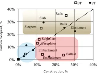
Figure 3 focuses on two main pieces of information regarding the sustainability of a track system: construction costs and carbon footprint. X-axis refers to the construction cost of a given item, e.g. rails, as a percentage of the total construction cost. Y-axis reports
the carbon footprint (CO2e) of the same item as a percentage of the
total CO2e. Ballasted track and ST are the options under analysis. Both
x and y variables are independent of prices fluctuations (assumed that the costs of the different items are linearly dependent) and from CO2e- associated cost. Three main importance levels are highlighted.
The first level includes rails, elastomers, slabs, and sleepers. Rails are a common component whose construction cost is about 25% and CO2e about 30%, while elastomers are mainly used in the ST, with a
construction cost of about 30% and a CO2eabout 25%. As for slabs, Table 4. Input data
Components Default Cost* (103 EUR)
Rails (ballasted/slab track) 240−300
Sleepers 115 Slabs 165 Ballast 226 Elastomer 369 Subballast 105 Concrete layer 53
Embankment (underneath ballasted/slab track) 120−200
Fastenings, Baseplates, Fixings 162
Annual maintenance costs of ballasted/slab track 30/8 Renewal costs of ballasted/slab track 818/1018
Traffic, MGT/year/km 6
Speed, km/h 200
Interest rate (r) 0.04
Inflation rate (i) 0.08
The carbon price, EUR/ton 11
490 THE BALTIC JOURNAL OF ROAD AND BRIDGE ENGINEERING 20 1 8/13 (4)
sleepers, being a cement concrete-based product, have a quite low cost (about 10−15%) and a quite high CO2e (about 25−30%). The second class
includes ballast, subballast, baseplates, and embankment. Construction costs range from 10% to 25%, while CO2e is lower than about 25%.
The remaining items, such as fastenings, baseplates, and fixings, have construction costs and CO2e lower than about 10%. Materials having
high mechanical performance and quite complex production process usually yield a correspondent construction cost and CO2e very high. In
contrast, materials such as soil and ballast or subballast (hot mix asphalt or cement treated course) (Oh, 2014; Praticò, Vaiana, & Giunta, 2013; Praticò, Vaiana, Giunta, Iuele, & Moro, 2013), although associated to significant construction volumes, yield quite low percentages regarding both construction cost and CO2e.
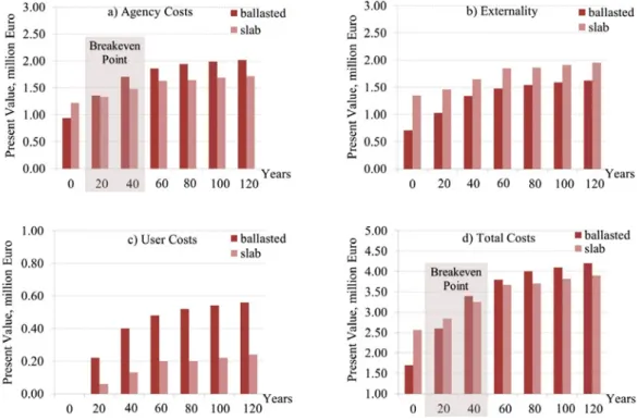
Figure 4a shows how the PV of the two options varies over time (AC). The assumptions were the following:
1) the costs of rehabilitation were considered equal to the construction costs for the given component, and this implies that the rehabilitation cost of STs is higher than the one of BTs;
2) the renewal activities are more time-consuming for STs.
The construction cost of the ST is higher than the one of the BT (1.2 million EUR vs 0.9 million EUR), but after just twenty years the slab solution exhibits a PV increasingly lower than the one yielded by the BT. This fact implies that starting from 20 years after construction, ST is better than BT (AC perspective). After about one century, the BT yields an overall (internal) PV 1.2 times higher than the one associated to the ST. Note that BEP stands for a breakeven point.
Figure 3. Construction versus carbon footprint
C ar b on f oo tp ri nt , % Construction, %
491
Figure 4b displays the PV of the UC over time. The fundamental element that underlies the results is that the maintenance process is slightly more expensive (regarding frequencies and durations) for the BT. Importantly, because of accidents, more data are needed for a comprehensive analysis. The magnitude of the PV for both of the solutions above appears consistent with the literature (Esveld, 2001; Pichler & Fenske, 2013; Schilder & Diederich, 2007). Apart from this observation, BT yields a cost 2.3 times higher than the one exhibited by the ST after the same period of analysis (more than one century).
Figure 4c illustrates the PV of the EX overtime for the options above. The as-built BT yields an EX (related to CO2 costs) lower than
the one associated to the ST, by a factor 0.8. Surprisingly, this tendency undergoes only slight modifications over time, being the ballasted solution still the optimal solution after more than one century.
Figure 4d illustrates the sum of the PV (y-axis) over time (x-axis). The breakeven point (above detected for about 20 years) now moves towards 40 years, due to the impact of CO2e-related costs. After more
than one century, the overall PV of the BT appears comparable to the one of the ST. The corresponding ratio accounts for an increase of just
492 THE BALTIC JOURNAL OF ROAD AND BRIDGE ENGINEERING 20 1 8/13 (4)
8%. Such a condition calls for a more in-depth investigation. In more detail, it appears noteworthy to underline that the same uncertainty, which is intrinsic to the estimate of PV (due to the variance associated with materials, processes, and environmental factors), allows justifying a certain caution in expressing a clear “dominance” of one solution on the other one. However, the results are consistent with the literature. Austrian studies (Mach, 2011) report a breakeven point for the total track costs after 24 years of operation, based on a daily track loading of about 70 000 gross-tons.
Finally, Figure 5 illustrates how the breakeven point (BEP, years, y-axis) of total costs varies as a function of traffic (gross ton kilometre, GTK, per year, x-axis). This sensitivity analysis points out that, under the given hypotheses, the higher the traffic is, the lower the BEP becomes, the more convenient the slab solution becomes.
Figure 5. Breakeven point of total costs vs traffic
a) 120 years b) 30 years
493
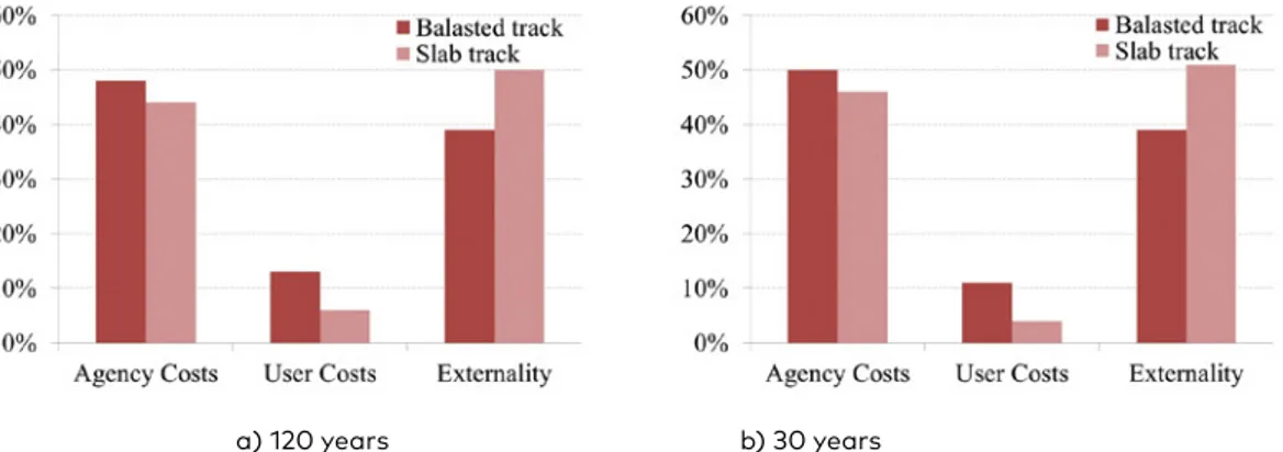
Figure 6 focuses again on time dependency. In Figure 6a the three classes of costs are compared, i.e. AC, UC, and EX’. Note that the apex (EX’) refers to the fact that costs were “balanced” to avoid
inferences biased by CO2 cost fluctuation. The period considered
is 120 years (approximately twice the expected life of PCC slabs), while the abovementioned two options are considered (BT and ST). Figure 6a shows that ACs and UCs are higher when the BT is considered.
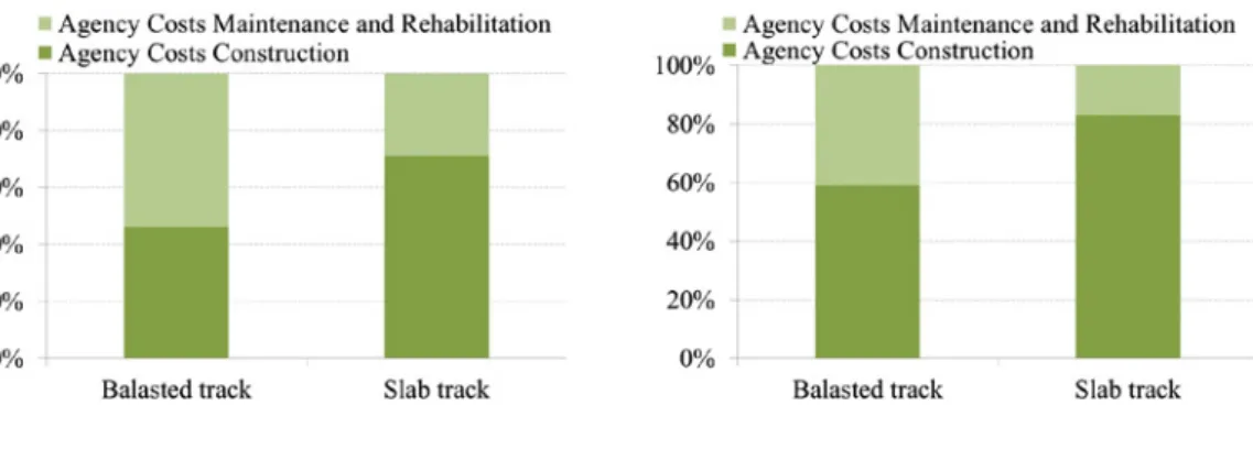
In contrast, the slab solution yields higher EX’. This result is crucial because it proposes again the familiar conundrum that often divides high-tech innovation from traditional solutions. The same applies to Figure 6b, where the period of analysis is lower than the one considered above. Figure 7a refers to agency costs and illustrates the comparison between construction (Constr) and Maintenance and Rehabilitation Costs (M&R), for the two solutions. Each solution (BT or ST) is scaled to 100%. The BT yields a lower initial cost (construction), while over time higher costs on maintenance and rehabilitation are needed. This occurrence plays an outstanding role in decision-making because of the available budget and because of the political process, which usually hinders from considering other choices. When the abovementioned evaluation, carried out after 120 years, is compared to a short-term analysis (Figure 7b), the percentage of cost referred to construction appears increased. This notwithstanding BT still yields a percentage distribution, which emphasises easier access to funding.
Finally, it is worth noting that further development of this study will emerge when LCC approaches are merged with RAMS and S-LCA approaches. Indeed, combined RAMS, LCC, and S-LCA methodologies for
a) 120 years b) 30 years
Figure 7. Construction versus Maintenance and Rehabilitation Costs
494 THE BALTIC JOURNAL OF ROAD AND BRIDGE ENGINEERING 20 1 8/13 (4)
railway and road transport infrastructures allow providing relevant and more comprehensive insights regarding investment and maintenance planning.
3. Discussion of results
Tangible and intangible costs govern the suitability of a track to fit transportation and environmental demand. Merging the technical issues and environmental concerns is a challenging task, and to this aim, a model has been formalised, based on the analysis of the cost of the cycle of life of BT and ST. The model allows considering environmental concerns as well as technical requirements and entails their balance through a specific and innovative algorithm. Care must be taken in deriving the external costs for a given scenario because reasonable assumptions are needed, especially when relevant laboratory and field data are unavailable for this purpose. The innovation of the paper pertains to the following main points. In this study, environmental impact and other costs are treated together: the well-known conundrum of dealing at the same time with environmental costs and remaining costs is herein solved through Eqs (8) and (9). This synergistic approach is innovative because the existing literature does not provide sound solutions to the issue of the fluctuation of EX. Consequently, the objectivity of comparisons is hindered from achieving a sound result because studies refer to a given historical period. The study described in this paper overcomes this drawback through the normalisation as per Eqs (8) and (9). Another issue of the existing literature refers to the consideration of just one life cycle. This fact implies that the relevance of financial flows is neglected or underrated. On the contrary, in this study real interest rates are considered for an infinite number of cycles. Eq. (3) illustrates this concept. The form of Eq. (3) contains the denominator (1− RD), which derives from the limit of a running sum.
Conclusions
Authors are aware that conducting such a comprehensive analysis requires big data sets. Anyhow, data gathered, and analyses carried out lead to the following conclusions.
1. Agency Costs cannot be analysed based on the sole construction costs in a short period. Indeed, although the magnitude of construction cost is very high (compared to the remaining costs), expected life has an appreciable impact. Consequently, solutions and systems
495 Filippo Giammaria Pratico, Marinella Giunta LCC-Based Appraisal of Ballasted and Slab Tracks: Limits and Potential
more affordable in the short-term yield maintenance, and renewal processes unfavourable: the best initial solution is the worst for long-term goals.
2. Maintenance and renewal processes affect both long-term agency costs and user costs, due to delays. High-frequency tracks and high-speed tracks result greatly influenced. This component cost depends on transport demand, and it turns out that these hypotheses affect results. Furthermore, railway traffic may change over time, due to new industrial settings, but it is important to observe that delays have exceptional importance regarding public opinion and this element makes the difference in referring to rail freight corridors or in contrast to high-speed tracks.
3. Ballasted tracks present environmental impacts lower than the one of the slab track system considered. Cement-related carbon footprint hinders the diffusion of slab track systems for minor applications. 4. From a more comprehensive standpoint, when tangible and
intangible costs are considered over track life, the breakeven point (between ballasted track and slab track) is “far” from construction, i.e. many years pass after the construction, depending on the level of traffic.
5. Overall, the “distance” between the total Present Values of the two solutions under analysis becomes too small to yield sound conclusions in favour of the ballasted vs the ballastless solution. This fact implies that the type of track (rail freight corridor, high-speed track, local tracks) causes a change regarding both algorithm output and decision-making.
6. Social concerns about safety and maintainability demand proper attention in the analyses above. This point calls for further research into the Social Life Cycle Assessment and Reliability, Maintainability, Availability and Safety analyses.
REFERENCES
Åkerman, J. (2011). The role of high-speed rail in mitigating climate change–The Swedish case Europabanan from a life cycle perspective. Transportation
Research Part D: Transport and Environment, 16(3), 208-217.
https://doi.org/10.1016/j.trd.2010.12.004
Andersson, M., Björklund, G., & Haraldsson, M. (2016). Marginal railway track renewal costs: A survival data approach. Transportation Research Part A:
Policy and Practice, 87, 68-77. https://doi.org/10.1016/j.tra.2016.02.009
Andrews, E. S. (2010). Guidelines for social life cycle assessment of products. UNEP/Earthprint.