DOTTORATO DI RICERCA IN
“SCIENZE DELL'INGEGNERIA”
CICLO XXI
COORDINATORE Prof. Stefano Trillo
Strategies for Multimedia content delivery
Dottorando
Tutore
Dott. Andrea Odorizzi
Prof. Gianluca Mazzini
_____________________ ______________________
1. Strategies for Multimedia content delivery . . . 1
1.1 Overview . . . 2
1.1.1 Multimedia Streaming peer-to-peer network . . . 2
1.1.2 Sensor networks delivery strategies . . . 3
2. Multimedia streaming peer-to-peer network . . . 5
2.1 P3P in brief . . . 5 2.2 State of Arts . . . 6 2.2.1 Scattercast . . . 7 2.2.2 Narada . . . 8 2.2.3 ALMI . . . 8 2.2.4 Overcast . . . 8 2.2.5 CoopNet . . . 9
2.3 Multiple Description Coding . . . 9
2.4 Architecture Overview . . . 11
2.5 Tree Management . . . 13
2.5.1 Parent and Child Metric . . . 15
2.5.2 Tree management goals . . . 15
2.5.3 Tree management protocol Client-side : join single mul-ticasting tree . . . 17
2.5.4 Tree Management Protocol Server-side: manage new peer . . . 21
2.5.5 Tree management Protocol: automatic recovery . . . . 26
2.5.5.1 Neighbor check . . . 26
2.5.6.1 Neighbor characterization . . . 28
2.5.6.2 Discovery procedure . . . 29
2.5.6.3 Join procedure . . . 32
2.5.6.4 Reject procedure . . . 35
2.5.6.5 Lock - Unlock procedure . . . 37
2.5.6.6 Optimizing procedure . . . 38
2.5.6.7 Recovery procedure . . . 39
2.5.7 Tree Management Protocol: initializing and updating node references . . . 39
2.6 Software implementation . . . 40
2.6.1 P3P packet header . . . 41
2.6.2 RTP and RTCP packet management . . . 43
2.7 Connection time analysis . . . 44
2.8 Evaluating performances . . . 48
2.8.1 Bushy tree strategies . . . 50
2.8.2 Distribution tree orthogonality . . . 54
2.8.3 Resilience against node failure . . . 58
2.8.4 Reconnection time . . . 63
2.8.5 Scalability of signalation traffic . . . 64
2.9 Conclusions . . . 67
3. Sensor Networks content delivery strategies . . . 69
3.1 Multisink routing . . . 70
3.1.1 Dissemination protocol . . . 71
3.1.2 Distance metrics definition . . . 73
3.1.3 Comparisons and results . . . 74
3.2 M-GeRaf . . . 77
3.2.1 Design rationale . . . 77
3.2.2 Evaluation of the path bifurcation probability . . . 80
3.2.3 Data delivery improvement . . . 85
3.2.5 Other back-off metric approach . . . 92
3.2.6 Position estimation error effect . . . 93
3.2.7 Conclusion . . . 95
4. Security in content delivery paradigm . . . 99
4.1 Application of wide trail strategy to an extended Feistel cryp-tosystem . . . 99
4.1.1 Block Encryption algorithm . . . 100
4.1.2 Uniform and Feistel transformation . . . 101
4.1.3 Chaos theory and Cryptanalysis . . . 102
4.1.3.1 Measure of diffusion . . . 103
4.1.3.2 Measure of linearity . . . 103
4.1.3.3 Differential Cryptanalysis . . . 104
4.1.3.4 Linear Cryptanalysis . . . 105
4.1.4 Filippini’s encryption scheme . . . 107
4.1.5 Linear and differential cryptanalysis: deterministic ap-proach . . . 108
4.1.6 Improved chaos based system . . . 109
4.2 Conclusions . . . 112
DELIVERY
Today, most of the existing traffic of the Internet will, not conveniently, be treated in a best effort basis.
Of the different traffic types carried, flows with audio and video content (multimedia traffic) have had a substantial growth in the last years, and their added value of edutainment motivates both academic and commercial research for solutions on improving the quality of such services.
Multimedia traffic has strict requisites regarding delays, jitter, packet losses and transmission rates. As traffic patterns change may very often and ca-pacity may differ for the various segments in the traffic path, disturbances are likely to happen and the Quality of Service (QoS) being offered to the users may be impaired.
To overcome such problems, there are mechanisms centered on the end sys-tems or on the network; some solutions may use learning techniques to better improve their performance over time.
At the end systems, efficient codification and compression algorithms help to improve the perceived quality of multimedia transmissions, and at the same time can generate flows with the most adequate characteristics (picture size, bit rate, etc.) for each type of terminal.
At the network level, there are mechanisms for differentiating traffic in IP networks, such as the Integrated Services (IntServ) model, the Differenti-ated Services (DiffServ) model and Multi-Protocol Label Switching (MPLS), where resources are allocated either through the use of static procedures or signaling mechanisms.
However, static procedures do not answer the needs of traffic dynamics, while signaling may involve a significant overhead to follow all traffic pro-file changes, scalability being a major issue here.
Moreover these static procedures require a dedicated infrastructure that can not be available or can not be realized in the analyzed networks (for example in sensor networks)
Learning algorithms may be included in QoS adapting solutions to improve over time the operational parameters at the network, to change the char-acteristics of the traffic itself when this is needed and feasible, or both of them.
Such an approach would examine the profile of traffic ingressing in the net-work and take proper measures to keep the system healthy.
1.1
Overview
The work presented in this thesis faces multimedia content delivery issues in different types of network, such as wired network, the Internet, ad hoc networks and sensor networks.
The term resource can refer to different concepts, since, there are several aspects that affect the performances and Quality of Service of the analyzed networks.
The studies discussed in this thesis are mainly referred to the following re-sources: the available bandwidth, the experimented delay, the experimented jitter and also, in wireless networks, the channel or communication medium to be shared among the networks participants and the energy available for the network nodes.
The aim is to find optimal solutions to allocate these resources in order to im-prove as much as possible the Quality of Service of the network under exam, in terms of various performance metrics, such as the achievable throughput, the latency and jitter, the energy saving.
The following subsections specify with more details how all these research items have been organized and presented in rest of the thesis. Chapters have been mainly divided accordingly to the type of network the techniques proposed are referred to: overlay network over the Internet, ad hoc and sensor network.
The last Chapter lies outside this subdivision since it refers to an aspect that is common to all the types of networks: the security enhancement of the communications through a shared channel.
Finally some conclusions are reported.
1.1.1 Multimedia Streaming peer-to-peer network
Chapter 2 is devoted to the study of a content delivery paradigm over the Internet.
In particular in this case the resources taken into consideration are the avail-able bandwidth and the experimented delay and jitter.
Overlay networks have been proposed as a way to improve Internet rout-ing, such as through quality of service guarantees to achieve higher-quality streaming media. Previous proposals such as IntServ, DiffServ, and IP Multi-cast have not seen wide acceptance largely because they require modification of all routers in the network. On the other hand, an overlay network can be incrementally deployed on end-hosts running the overlay protocol software, without cooperation from ISPs. The overlay has no control over how pack-ets are routed in the underlying network between two overlay nodes, but it can control, for example, the sequence of overlay nodes a message traverses before reaching its destination.
This Chapter proposes a new overlay network, focuses on the resilience of this distributed approach and proposes techniques whose aim is to preserve the user perceived Qos also during the peer (overlay network node) failure events.
The proposed strategy merges application layer techniques and overlay rout-ing layer ones in order to takes advantage of both the available information.
1.1.2 Sensor networks delivery strategies
Chapter 3 focuses on delivery paradigm in wireless sensor networks environ-ment.
Geographic routing (also called georouting or position-based routing) is a routing principle that relies on geographic position information. It is mainly proposed for wireless networks and based on the idea that the source sends a message to the geographic location of the destination instead of using the network address.
Geographic routing requires that each node can determine its own location and that the source is aware of the location of the destination. With this information a message can be routed to the destination without knowledge of the network topology or a prior route discovery.
In particular, in order to increase the energy efficiency Chapter 3 proposes a new random geographic routing multisink-multicast approach that does not require any signalation traffic messages. Finally it analyzes the performances and the applicabilty of the proposed routing and delivery protocol.
NETWORK
The problem of distributing live streaming media content without any dedi-cated or available infrastructure could lead to peer-to-peer architecture able to establish a generic collaborative environment. The aim of these distributed platforms is to provide an environment in which every peer will be able to share all the media required in the collaborative sessions i.e., synchronous e-learning sessions, video-conferences. . .
A peer-to-peer approach allows to scale the required resources, i.e., band-width, . . . , with demand (the amount of interested client) and could allow a performance optimization establishing an overlay network structure. Self-optimizing structure is pivotal in collaborative environment in which partic-ipants interact with each other for a long time and in which some of them can leave the session unexpectedly.
The greatest challenge of a peer-to-peer overlay network environment that deliver real time multimedia content is to increase the content distribution resiliency against peer transience.
In the following a distributed approach, named P3P,[1][2], is discussed. P3P is based on tree-structured (therefore Peer tree Peer) overlay network and provides a management protocol that allows structure optimization and also peer failure management.
2.1
P3P in brief
The target scenario of the discussed real time collaborative environment are made by participants that would establish a multimedia session, for example, from a foreign network i.e., a network of an organization which is not the one in which the participant ”lives”. In addition, collaborative session could be infrequent and irregular and could not justify charges related to a dedicate infrastructure that should be sized to serve the maximum amount of client. Due to the lack of wide spread support for IP Multicast, the simultaneously distribution of the same multimedia content to a potentially large group of
client requires a set of resources that could not be commonly available by everyone.
Today overlay multicast can be an alternative to IP multicast [3], [4], [5], [6], [7]. An overlay network is a computer network which is built on top of another network. Nodes in the overlay can be thought of as being connected by virtual or logical links, each of which corresponds to a path, perhaps through many physical links, in the underlying network. The overlay has no control over how packets are routed in the underlying network between two overlay nodes, but it can control, for example, the sequence of overlay nodes a message traverses before reaching its destination
A P2P based overlay approach avoids single participant resource limitation by scaling the request resources with demands. Every multimedia content is produced by a single Peer and has to be delivered to all the other ones, hence establishing a multicasting tree structure is an obvious choice also used in many overlay multicast structures [4], [5].
Tree structure can bound the resources requested to each single peer but introduces a great limitation: every peer is the root node of its own sub-tree and each single peer failure could compromise the service delivery to a potentially large subset of peer.
A simple but effective solution is to use network path redundancy; this possi-bility becomes very attractive with the introduction of Multiple Description Coding, [8], that merges network path redundancy with data one.The Coop-Net project, [9], developed by Microsoft exploits this strategies.
Multiple description coding is a method of encoding an audio and/or video signal into separate streams, or descriptions, such that any subset of these descriptions can be received and decoded. The distortion with respect to the original signal is commensurate with the number of descriptions received; i.e., the more descriptions received, the lower the distortion and the higher the quality of the reconstructed signal. P3P establishes a multicasting tree for each description of the delivered multimedia content.
2.2
State of Arts
Following the classification of [10] many overlay multicast projects can be classified into two catalogs according to the structure: end-to-end overlay and proxy-based overlay. In end-to-end overlay, every member in the multicasting group shares the responsibility to forward data to other members. End hosts self-organize into a multicasting tree. These end hosts are called multicast nodes in this case. Narada [4], Yoid [3] and ALMI [7] are some examples of
such structure. Using the proxy-based overlay structure, Scattercast [5] and Overcast [6] form a hierarchy structure compared to end-to-end overlay. The multicasting service is fulfilled with the help of proxy-based multicast nodes, which can duplicate data and forward data to end hosts with predefined routing algorithm. The concept of multicast node is slightly different in two structures, but in both cases, a multicast node is defined as a member in the multicasting tree.
In the following four projects that are representative of overlay multicast are briefly introduced: Scattercast, Overcast, Narada and ALMI. The design objectives are different from each other which lead to differences in their design approaches and properties in many aspects.
Narada and Scattercast intend to minimizing delay for each member; how-ever, Overcast maximizes available bandwidth for each member. ALMI tries to minimize the system cost, where the cost of each link is defined as the round-trip delay between group members.
Narada and Scattercast use a mesh-first approach, that is, group members are connected in a mesh first and then the multicast tree is built on top of the mesh. Overcast and ALMI use a direct approach. In this case, the step to build the mesh is bypassed and the multicast tree is formed directly. Overcast and Scattercast claim good scalability, the other two only can serve dozens of members.
2.2.1 Scattercast
Scattercast is an overlay architecture to carry out multicasting by incorpo-rating proxy-based multicast nodes.
When a new node joins a multicasting session, it bootstraps itself via a well-known list of rendezvous points and then relies on the gossip-style discovery algorithm to locate other members. When the new node encounters other members who have already been in the session, it selects some of them as its neighbors if they satisfy the degree constrains.
The initial mesh is randomly formed. When performing optimization, la-tency is the primary metric considered. Member decides to accept others as neighbors or to change neighbors according to a predefined cost function and threshold. After the mesh is stable, a distance vector routing protocol [11] is running on the top of the mesh, taking latency between neighbors as its routing metric.
2.2.2 Narada
Narada intends to serve small size and sparse groups such as audio-video conferencing and virtual classrooms.
Narada and Scattercast use the mesh-first approach, but are different in pro-cess of mesh optimization. Narada assumes that the new node is able to get a list of group members by an out-of-band mechanism. It randomly chooses some members as its neighbor if those members would not exceed their max-imum degree constraint. It exchanges messages with its neighbors to learn other members.
Every member periodically evaluates the utility of adding a link and deleting existing links to decide the further optimization.
The way of building a data delivery tree and routing is the same as Scatter-cast.
2.2.3 ALMI
The design goal of ALMI is to minimize the cost of the system, that is, the cost of the distribution tree. The distribution tree in ALMI is formed as a Steiner Minimum Tree, SMT, where the cost of each link is the latency of the link.
The operations in ALMI greatly depend on the central control server, which collects the latency information and calculates a SMT to be sent back to all members.
Such a centralized control approach simplifies the routing problem compared to a distributed approach, however, it only works for a small communication group and also suffers from the single-point failure problem.
2.2.4 Overcast
Overcast directly builds multicast trees to maximize bandwidth to the source for all members at the expense of the potential to increasing of delay. When a newly initialized node join the group, it contacts the root as the first step. Then the new node re-evaluates its position and tries to locate itself further away from the root without sacrificing bandwidth back to the root. In each re-evaluation round, the node evaluates the bandwidth to the cur-rent pacur-rents and the bandwidth to the children of the curcur-rent pacur-rents. If the bandwidth through any of the children is about as high as the current bandwidth, that child will be chosen as the current parent.
With such a strategy, the node will be located as far from the root as possible without reducing bandwidth.
2.2.5 CoopNet
All the previous projects are not addressed to realize a resilient peer-to-peer architecture and marginally consider the problem of a peer failure or the possibility of join to the multimedia session for a very short time compared to the other peer session duration.
Multimedia description coding offers the possibility of receive different de-scriptions of the same multimedia content fron different sources hence it allows the realization of a resilient distributed architecture in which a peer failure does not compromise the service delivery. CoopNet projects, [9], ex-ploits this possibility; it organize the peers in different distribution trees, one for each description.
The CoopNet distributed architecture is managed by a central server that organizes peer tree evolution, decides the MDC parameters and also can serve a large amount of client.
CoopNet architecture is designed to deliver the same multimedia content to a very large set of client (often with a very irregular connection time) and the aim of the optional distributed peer-to-peer network is to aid this central server.
2.3
Multiple Description Coding
Multiple description coding, MDC is a method of encoding an audio and/or video signal into M > 1 separate streams, or descriptions, such that any subset of these descriptions can be received and decoded.
The distortion with respect to the original signal is commensurate with the number of descriptions received, i.e., the more descriptions received, the lower the distortion and the higher the quality of the reconstructed signal.
This differs from layered coding in that in MDC every subset of descriptions must be decodable, where as in layered coding only a nested sequence of subsets must be decodable.
Many multiple description coding schemes have been investigated over the years. [8] contains a simple overview. A particularly efficient and practical system is based on layered audio or video coding, Reed-Solomon coding, and priority encoded transmission.
In such a system the audio and/or video signal is partitioned into groups of frames (GOFs), each group having a duration of T = 1 second or so, for example. Each GOF is then independently encoded, error protected, and packetized into M packets, as shown in Figure 2.1. Both layered coding and Forward Error Correction (FEC) are building blocks for MDC.
Distortion
Rate
Embedded bit stream
R(0) R(1) R(2) R(M)
Packet 1
Packet M Packet 2
Packet 3
Fig. 2.1: Priority encoding packetization of a group of frames (GOF). The source
bits in the range [Ri−1, Ri) are mapped to i source blocks and protected
with Mi FEC blocks. Any m out of M packets can recover the initial
Layered coding is used by MDC to prioritize the streaming data. The bits from a GOF are sorted in a decreasing order of importance (where importance is quantified as the bit contribution towards reducing signal distortion) to
form an embedded bit stream. For example, bits between R0 and R1are more
important than the subsequent bits in the embedded stream in Figure 2.1. Forward Error Correction (FEC), such as Reed-Solomon encoding, is then used to protect data units to different extents depending on their importance. M descriptions can accommodate up to M priority levels for a GOF. If any
m ≤ M packets are received, then the initial Rm bits of the bit stream for
the GOF can be recovered, resulting in distortion D(Rm), where 0 = R0 ≤
R1 ≤ . . . ≤ Rm and consequently D(R0) ≥ D(R1) ≥ . . . ≥ D(Rm). Thus
all M packets are equally important; only the number of received packets determines the reconstruction quality of the GOF.
A smart tuning of MDC parameters, i.e. total number of descriptions, GOF durations, . . . , requires, for example, a very accurate estimations of the prob-ability distribution of the amount of received descriptions.
The problem of tuning the parameters of MDC, that is pivotal in order to optimize the perceived quality of service, is beyond the scope of this discus-sion. Instead of a distortion analysis approach in the following is used an heuristics metric in which the measure of the perceived quality is only the amount of received descriptions: the more descriptions received, the higher the quality of the reconstructed signal.
2.4
Architecture Overview
Following the classification of [10] P3P project can be classified into end-to-end overlay network set; every member in the multicasting group shares the responsibility to forward data to other members and all together they organize theirself into a multicasting tree.
The entities of P3P architecture are Peer and User Agent (UA). The UA is the human front-end that transmits and receives all the multimedia streams; the peer, which is a node of the multicasting tree, act as a proxy from the UA point of view, and serves a small amount of UAs delivering to them the streams received in the multicasting tree, figure 2.2.
Peer and User Agent are not necessary separated and they could collapse in a single object, but dividing them allows to decouple the overlay multicast structure from the specific front-end application. Moreover it allows to take advantage of local IP multicast infrastructure: P3P could be used also in order to connect different multicast network.
Fig. 2.2: Architecture overview, all the peers establish an overlay multicasting tree network and deliver or receive multimedia contents to their own UAs
The mean of the local network peer-UAs interaction environment, the one in which all the UAs are connected to the same peer, is to quickly connect a small amount (2 or 3) of participants without increase the global struc-ture load: all the UA connected to the same peer communicate directly to each other and, if a UA is a stream source, it will send a copy of the cap-tured streams to the peer that can encode them in different description and propagate them through the multicasting tree.
No infrastructure means no rendez-vous server. Following the bit-torrent example a small .p3p file could be published over a well known web site or could be sent by mail. The obtained .p3p file contains all the information required in order to contact the root peer or another node of at least one multicasting tree.
Each peer that know the information included into .p3p file will automat-ically integrate itself in the overlay multicast structure following the tree management protocol rules. Like in Scattercast, section 2.2.1, nodes boot-strap theirself via a well-known list of rendezvous points and then rely on the gossip-style discovery algorithm to locate other members.
path redundancy.
In order to avoid lack of services due to peer failure events network path redundancy is pivotal : If the streaming content is encoded using MDC, different description will be distributed over different distribution trees hence peer failure does not always compromise all the description received from a potentially large sub-set of peer, because the same set of peer, in another distribution tree, could not be positioned into a failed node subtree.
In Figure 2.3 is depicted a very simple situation in which root peer, the one that introduces multimedia content into the multicasting tree, distributes two description through two different trees. The effect of the a-peer failure event is reduced to a simple degradation of the perceived quality at nodes b,c,e and does not lead to a complete out of service for this particular subset of node.
Different overlay distribution trees have to be as orthogonal as possible, i.e. the higher is the amount of shared overlay network links, the higher is the probability of a node sub-set out of service or heavy quality degradation event.
Furthermore, adopting MDC, P3P can realize a differentiated class of ser-vice: peers with poor available bandwidth resources can join only a reduced amount of distribution tree hence receive a reduced amount of description. MDC can also aid peers to manage starvation situation: reducing the amount of forwarded descriptions a peer can deliver the reduced set of description to an enlarged amount of child node.
Each peer delivers as much description copy as allowed by its available band-width; during tree optimization phase could be convenient to temporarily accept lots of child nodes (for example in order to aid nodes that will be relocated into the tree structure) and this strategy could be realized by re-ducing the amount of description copy delivered to the current child nodes.
2.5
Tree Management
In this section the problem of constructing and maintaining a single overlay distribution tree is discussed.
Unlike [9], in which each description or distribution tree is organized by the central server, in P3P each tree structure grows and tries to optimize itself, at first, through a greedy algorithm and, hence, using a distributed local search optimization.
In the following discussion all the nodes participate and contribute to re-sources sharing until the end of the session or until a failure event.
Root
Distribution tree 1
Distribution tree 2
a
b
c
d
e
Fig. 2.3: Distribution Trees, Root node produces 2 descriptions of the same
multi-media content that are delivered through two different overlay distribution trees
2.5.1 Parent and Child Metric
Unlike [3], [4], [5], [6], [7] that decide the overlay network evolution evaluating a single parameter (bandwidth, delay, . . . ) measured by each peer, P3P adopts two evaluation metrics in order to decide which peer could be a good parent node or which peer could be a good child node. Each peer takes its decisions comparing the neighbour peer attributes and/or the attributes of peer that is interacting with it.
• Parent metric is used in order to decide which peer could be the better parent node in the overlay multicasting tree and is based on
– the evaluation of peer level, i.e.,the amount of intermediate nodes
between the tree root and the candidate parent node
– the measured round trip time
– the the amount of common ancestor node,i.e., node between the
tree root and the candidate parent node, between different distri-bution tree.
• Child metric is used in order to decide if a peer could be accepted as child node in the everlay multicasting tree compared to the actual child peers; it is based on
– the outgoing bandwidth published by child candidate peers
– the current outgoing available bandwidth of the same node (child
node candidata can be a root of an overlay subtree)
– the amount of common ancestor node
– the measured round trip time
Tentatively a parent peer is better than another one if its level is lower than the other one level, instead a child node is better than another one if its outgoing bandwidth is greater than the one of the other node.
Morevoer the metrics could and should be tuned in order to advantage the influence of some parameter. Nevertheless bandwidth evaluation are pivotal in order to reach the goals listed in section 2.5.2
2.5.2 Tree management goals
The goals of the discussed single tree management algorithm are the follow-ing:
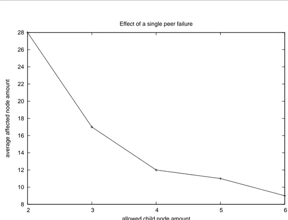
8 10 12 14 16 18 20 22 24 26 28 2 3 4 5 6
average affected node amount
allowed child node amount Effect of a single peer failure
Fig. 2.4: Average amount of node affected by a single peer failure in a 255 nodes
single distribution tree
- Bushy trees: P3P tries to reduce the height of each tree structure i.e., it minimizes the amount of intermediate nodes between the root node and the further away nodes. Shortness would minimize the introduced overlay multi-hop delay and than minimizes the probability of sub-tree disruption due to peer failure event.
In figure 2.4 is depicted the effect of enlarging the child node amount: it can reduce the average number of nodes affected by single peer failure event.
Each node selects its own child nodes evaluating the Child metric values of all current child nodes, if at least one exists, and evaluating the metric value if the new incoming child node candidate.
Each node that searches a parent peer, sorts the peers that could be-come his own parent node by evaluating Parent metric over all the parent node candidates.
Nodes with large outgoing bandwidth, hence, potentially lots of chil-dren, will obtain a low level in the distribution tree therefore each over-lay tree becomes as bushy as possible without external or centralized coordination.
- Soft handover: If a parent node that delivers multimedia content to its maximum amount of child node receives a join request sent by an interesting child candidate node, i.e., a peer that exhibits a child metric value greater than at least one of the current child node value, the current child node with the lower metric has to be relocated into the P3P structure.
In order to avoid services interruption, descriptions directed to each child node has not to be stopped until the rejected child node finds a new parent one.
- Gossip-style signaling: In order to reduce the signalation traffic discovery messages i.e., messages used to locate system resources, are carried following the overlay network established paths: each node for-wards the incoming discovery message over all its established interface (parent, child a, child b,. . . ) but the one from which the message has been received. All the other type of signaling message involves only two peers that communicate directly.
- Smart optimization: P3P sessions could be very long and the under-lying network properties could significantly change during each multi-media session. In order to follow the underlying network status, if a peer register a stable situation, i.e. does not receive signaling message for a significantly time period, it will try to optimize its own position into a distribution tree.
- Smart failure recovery: After a peer failure at least one sub-tree register a perceived quality decreasing. In order to avoid a discovery flooding, only child nodes of the fault peer have to search a new parent node; other nodes in the orphaned sub-tree wait for an ancestor node driven reconnection.
2.5.3 Tree management protocol Client-side : join single multicasting tree
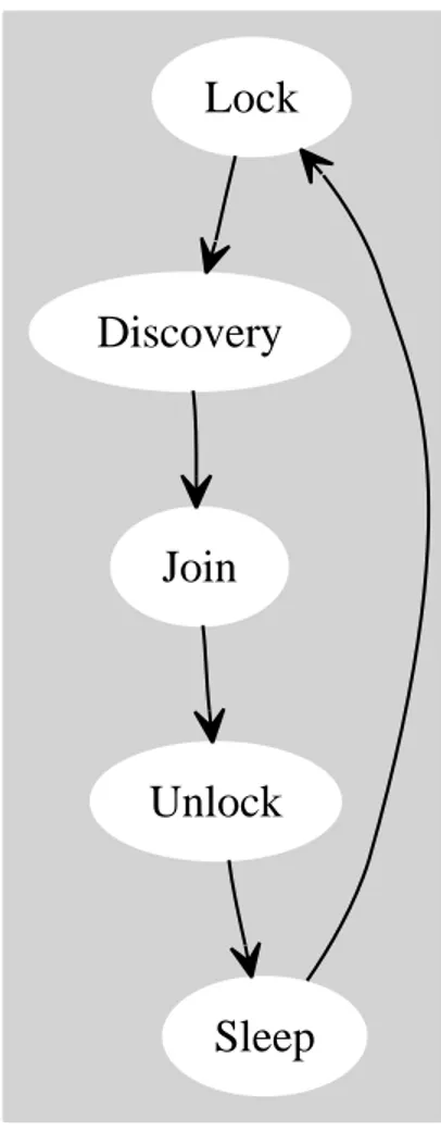
In order to join to the P3P platform in the behavior of the joining peer could be identified five different macro states, figure 2.5, each one related to a specific interaction between the peer and the overall P3P structure.
• Lock: In order to avoid loop creation during simultaneous sub-tree migrations each node that has to move from a parent node to another one has to prevent incoming join requests in its own sub-tree.
• Discovery: the aim of discovery phase is to aid node that tries to join to the structure has to know which is the set of possible
accommoda-tion into the distribuaccommoda-tion tree and, moreover, which are the nodes that constitute the multicasting tree in order to chose the best available position.
• Join: During the Join phase resources have to be allocated from nodes in the P3P structure to the joining peer. After Discovery conclusion each node selects the better parent candidate node evaluating parent metric and, finally, try to join the structure.
• Unlock: Unlock phase is used in order to renew the possibility of external nodes to join into the locked sub-tree.
• Sleep: Sleep is the macro state in which the peer does not perform any tree management procedure in order to modify its own position into the distribution tree structure.
The sequence of macro state in figure 2.5 performs the basic flow used by peers in order to join a multicasting tree.
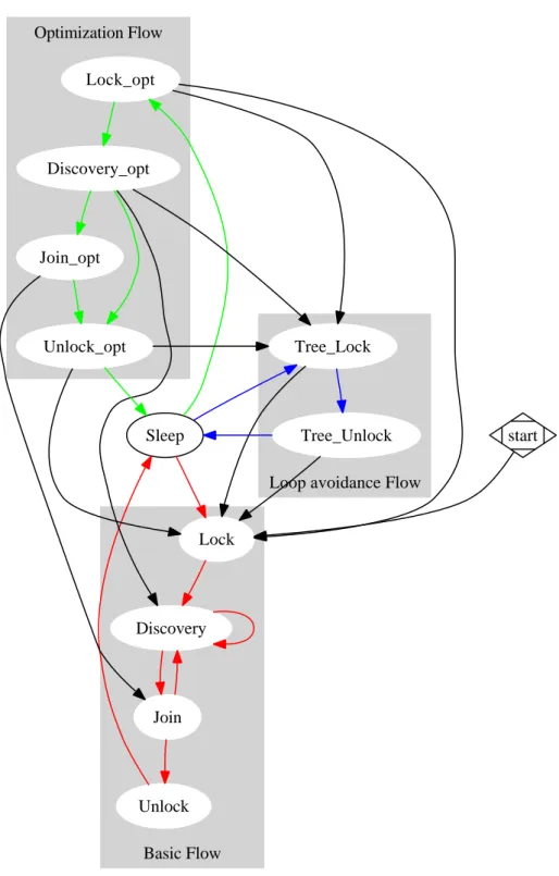
Nevertheless the same flow with some obvious differences is used in order to optimize node positions into the multicasting tree and, also, in order to perform sub-tree lock and unlock procedures originated by ancestor node. In figure 2.6 these three flows are depicted:
• Basic flow is the red one. It is performed in order to find at least a new parent node. For example nodes that start a new session perform the red flow. Another example happens when a parent node decides to relocate one of its child nodes: removed child nodes perform the red flow. At last red cycle is performed when peer detects the parent node failure event.
• Optimization flow is the green one. It is performed in order to obtain a better position into the multicasting tree structure. After sleeping for
a specified time period, timeoutf lat, each node starts an optimization
procedure: it starts to lock its own subtree and then performs the discovery procedure hence, if possible, it performs the join procedure. Unlike basic flow if the discovery procedure does not find any parent node, if discovery procedure finds only parent candidate nodes with parent metric values smaller than the current parent one or if the join procedure does not complete with success, the optimization flow contin-ues with the unlock procedure and does not contine to search a parent node executing another discovery.
Lock
Discovery
Join
Unlock
Sleep
Fig. 2.5: Macro state sequence of the basic execution cycle performed by a node
Basic Flow Optimization Flow
Loop avoidance Flow
Lock Discovery Join Unlock Sleep Lock_opt Tree_Lock Discovery_opt Join_opt Unlock_opt Tree_Unlock start
Fig. 2.6: State diagram of the execution flow performed by the client side of a node
Vice versa the execution flow migrates into the basic one, the join pro-cedure is completed and a better position into the distribution tree is obtained.
• Loop avoidance flow is the blue one. It is a simplified flow driven by an ancestor peer that decides to lock (and unlock) its own subtree. Each flow has got a priority and the execution flow can not migrates from flows with higher priority to ones with smaller one. In detail the basic flow has a priority higher than the loop avoidance one, whose priority is also higher than the optimization flow.
For example nodes that try to optimize their position and receive a lock request from their parent node leave the green flow and start the blue one, but nodes that have to find, in the red cycle, a parent node ignore the incoming lock request.
A much detailed executing flow graph is depicted in figure 2.7 in which the elements of figure 2.6 is not grouped by flow
2.5.4 Tree Management Protocol Server-side: manage new peer
In order to manage the distribution tree join request of the incoming peers, the behavior of each peer that receives and manages the join request message could be simplified in the sequence of the following macro states:
• Join: In this macro state a new join request is managed. The peer evaluates, with the aid of the child metric, if the incoming child node candidates could be accepted or not. If the incoming node can not be accepted, i.e., peer outgoing resources are not available or dedicated to child nodes with greater child metric, peer stops the join procedure and returns in the sleeping macro state.
• WaitingConfirm: In this macro state peers that have accepted a join request are waiting for join confirm message from the incoming peer. If the confirm is negative peers will return in the sleeping macro state. • Allocate: In this state peers that have received a positive join con-firm message allocate the outgoing resources requested by the incoming child nodes.
• Reject: If the peer outgoing resources are completely allocated but the incoming child candidate peer metric values is greater than at least one of the current child node ones, the new incoming child will be frozen
Start Lock Sleep Locking Locking_opt Tree_locking Discovering Lock_opt Tree_lock Discovering_opt Tree_unlocking ReadyToJoin ReadyToJoin_opt Unlocking_opt Joining Joining_opt Join Unlocking Join_opt Unlock Unlock_opt Tree_unlock
Fig. 2.7: State diagram of the execution flow performed by the client side of a node
Sleep
Join
Reject
WaitingConfirm
Deallocate
Allocate
Fig. 2.8: Macro state sequence of the basic execution cycle performed by a node
until outgoing resourced will be relocated. A reject request is sent to the worst child node (the one with the smaller child metric) and peer still wait for the reject reply.
• Deallocate: In this state peers deallocate the outgoing resources dedi-cated to their worst child peers and reply to the incoming child in order to complete the previous join procedure.
• Sleep: In this state peers wait for incoming join requests.
The sequence of macro state in figure 2.8 constitutes the basic execution flow exploited in order to accept a new peer in each distribution tree structure. Nodes in the P3P structure interact not only with the incoming peer but also with neoghbor nodes in the overlays. The execution flow depicted in in figure 2.9 is grouped into the three sub-flows that have to be managed by a peer in order to accept or not an incoming child node and takes into account of neighbor interactions.
• Join Management Flow Is the execution flow performed if the peer receives a join request. Green sub-flow is performed if the node can allocate immediately resources for the incoming peer otherwise the red one is performed. The difference between red sub-flow and green one is that, in order to allocate resources, the peer has to remove one, the worst, of its current child nodes. The worst child node is the one with the smaller child metric.
At the end of resources deallocation join procedure is performed: in-coming peer, that is waiting for the definitive join reply, could continue the join procedure with an handshake and peer resources are reallo-cated.
The join procedure can manage only one child node at a time. Brown flow takes into account the possibility of receive more than one requests. Like in the reject phase, after receiving multiple requests, incoming nodes are frozen in order to complete the current join procedure. If multiple frozen child nodes exist the new join procedure involves the node with the greatest child metric.
• Deallocate Resource Flow Is the flow performed at the reception of an unrequested Reject Reply ( for example at the end of a successful optimization procedure performed by a child node). The effect of this event during all the execution flows is the same: resource deallocation. This event also affects the join execution flow ( see purple macro state transitions in figure 2.9).
Join Management flow
Deallocate Resource flow
Looop Avoidance flow
Sleep Join Join_f Deallocate_r Locking WaitingConfirm Allocate WaitingConfirm_p WaitingConfirm_l Allocate_l Reject Deallocate Reject_l Deallocate_l Join_p Allocate_p Join_pf Reject_p Deallocate_p Reject_f Deallocate_f Reject_pf Deallocate_pf Lock Unlocking
Fig. 2.9: State diagram of the execution flow performed by a node in order to
accept and manage a join request message
• Loop Avoidance Flow Is the flow performed in order to block the peer sub-tree and it is triggered by the reception of a lock request from parent node. This event affects all the other execution flow: see blue transition in 2.9. During this transition all the frozen incoming child nodes will be rejected by the peer and only the current incoming child peer or the current reject phase will continue their executions in the locking Flow.
Unlocking sub-tree procedure is also triggered by a parent node request. Loop Avoidance flow is performed with an higher priority than Join Manage-ment flow. Therefore peers in the join flow can migrate in the loop avoidance flow and peers in the loop avoidance execution flow ignore all the incom-ing join request. Deallocation flow is performed with the highest priority:
resource deallocation has to be completed as soon as possible in order to relocate immediately the resources.
A much clear execution flow graph is depicted in picture 2.10 in which the element in figure 2.9 are not grouped by flow.
2.5.5 Tree management Protocol: automatic recovery
Both client-side and server side execution flow rely on the idea that each incoming peer, ech child peer, each parent candidate peer and each parent peer are running and can reply to the analyzed peer messages.
In order to take into account of peer failure the following recovery procedures
are performed at each timeoutneighbors:
2.5.5.1 Neighbor check
• CheckParent: Peer sends a keep-alive message to the parent and checks the last reply timestamp. If the last reply timestamp is
out-dated (older than timeoutdead milliseconds) a pparent failure event is
supposed and a new parent search is triggered.
• CheckChildren: Peer checks if the last ingoing keep-alive message of every children is outdated. If so the dedicated children resources are immediately deallocated.
Previous check are based on the following message handshake that is triggered by the CheckParent evaluation.
• ChildAlive message If peer receives an incoming alive request from child node it replies and waits for the confirm message
• ChildConfirm message If peer receives the alive confirm message updates the calculated RTT between it and its own child node.
• ParentReply message If peer receives a alive reply from parent node it sends an alive confirm message and update the calculated RTT be-tween it and its own parent node.
Performing these recovery strategies outgoing resources can be relocated, peer failure can be managed and new parent discovery will be forced.
Sleep Join Join_f Deallocate_r Locking WaitingConfirm Allocate WaitingConfirm_p WaitingConfirm_l Allocate_l Reject Deallocate Reject_l Deallocate_l Join_p Allocate_p Join_pf Reject_p Deallocate_p Reject_f Deallocate_f Reject_pf Deallocate_pf Lock Unlocking
Fig. 2.10: State diagram of the execution flow performed by a node in order to
Keepalive Neighbour check Sleep ChildAlive ParentReply CheckParent ChildConfirm ParentChecked ParentFailed CheckChildren TriggerLockingAndDiscovery ChildChecked ChildFailure Deallocate
Fig. 2.11: Recovery execution flow
2.5.6 Tree management Protocol: procedures in detail
2.5.6.1 Neighbor characterization
Each node updates a image of the overlay P3P network based on the other peers received messages.
In this image each neighbor has to be identified within a particular state that identifies the relation in the P3P structure between the peer and the neighbor node.
Peer behavior decisions are taken based on this states but also on the other data stored in the P3P image,i.e., all the remote peer published attributes, and on current incoming messages.
Remote peers are classified into the following states:
- unknown a peer that cannot be identified as a neighbor
- probed a peer that has replied to a discovery request. It is not posi-tioned in the peer sub-tree
- parent candidate the best probed peer (the one with the higher
par-ent metric) at the timeoutdiscovery expiration; The join request messages
- parent the peer which has accepted the join request. Only one parent node per tree should exist. Parent node allocates a fraction of its outgoing resources and pushes the received distribution tree contents to the peer.
- bad parent a parent node that would reallocate its outgoing resources from the examined node to another peer; it periodically sends a reject request to the analyzed node but it will continue to push the tree distribution content until the peer replies to the request with a reject reply message.
- child node that receive a copy of the distribution tree content and for which a fraction of outgoing resources are allocated.
- frozen child a possible child node whose join request could not to be immediately accepted. A node could be identified as frozen child because parent node has to complete a reject procedure or another join procedure. Neither resources are allocated for frozen child nodes until they become child node.
- joining child a node that is going to become a child one. It will become a child node only after the join confirm message reception. No resources are allocated until joining ones become child node.
- rejected child a child node that has to be removed in order to relocate its dedicated outgoing resources. The distribution tree content has to be pushed to it until a reject reply message is received.
2.5.6.2 Discovery procedure
Discovery procedure are not reliable and requires the execution of lock pro-cedure before it can be performed. In figure 2.12 node Q sends a discovery request message to its own current parent node or, if it does not exist, to the
distribution tree root node and waits for the timeoutdiscovery expiration. The
current parent node could be both parent and bad parent node.
Node that receives the request forwards the message to all the neighbor nodes but the one from which the request is received. Moreover nodes that are locking their own subtree do not propagate the discovery request to their child nodes.
All peers that receive a discovery message forward it, but reply to Q only if child metric of Q is larger than at least one of the child node metric evaluated values or if they can accommodate immediately another child node.
Fig. 2.12: Discovery phase, Q sends the discovery message to a known Peer, (1), that forwards it to the child nodes and to the parent node, (2), that forward the message too, (3).
In order to reduce signalation traffic if a peer replies to Q it does not forward the discovery request message to its child nodes: In each subtree child node parent metric values are always smaller than the parent node parent metric one.
Discovery reply message is sent directly to Q and not use the overlay es-tablished path. If Q receives the reply messages it will set the state of the remote peer to probed node and it will learn that the sender is not in its sub-tree.
At the timeoutdiscovery expiration Q evaluates the set of probed node and
elects the best one, the one with the larger parent metric value, as parent candidate node.
Discovery reply is also used to measure the path delay between peers:
1. Discovery reply is sent at time treply (saved by the remote peer).
2. Q receives the discovery reply message at time tr2 and sends back a
RTT request message to the remote peer;
3. Remote peer receives the RTT request message at time tr3; it estimates
RTT as RT Tmeasured = tr3 − treply and sends a RTT Reply message to
Q.
4. At time tr4Q receives the message and estimates RTT as RT Tmeasured=
tr4− tr2
Both peers use an IIR filter for a tight round trip delay estimation (RT Test).
RT Test = (1 − α)RT Tmeasured+ αRT Test (2.1)
Discovery procedure require a time period TDiscovery that can be calculated
as
TDiscovery = Tcheck+ timeoutdiscovery ∼= timeoutdiscovery (2.2)
where Tcheck is the average value of Tcheck, the time period used by the P3P
peer to trigger synchronous event such as start of a new synchronous proce-dure, detection of timeout expirations, . . .
In equation 2.2 Tcheck takes into account of the time period between the
event that trigger the discovery procedure and the effective discovery start.
Nevertheless Tcheck is significantly smaller than the average RTT that is also
significantly smaller than TDiscovery.
Discovery procedure is performed for the first time when Q reads the .p3p file that contains the address of the rendez-vous node but is also performed
when parent node have to relocate the dedicated outgoing resources (reject procedure, section 2.5.6.4) and also when Q tries to optimize its position into the multicasting tree (optimization procedure, section 2.5.6.6).
Discovery procedure is essentially a client-side procedure: receiving a discov-ery request does not modify any execution flow in the server-side execution flow graph, figure 2.10. As depicted in figure 2.7 the discovery procedure could be executed both in the basic flow that in the optimization flow. As explained the main difference between these two invocations of the same
procedure is the behavior at the timeoutdiscovery expiration time; if any peers
do not reply yet, i.e., no probed peer exist, during the optimization loop the peer starts to unlock its own subtree finishing its optimization attempt but, in the basic loop, the discovery procedure will be repeated.
Moreover, during the execution in the optimization flow, discovery procedure could be stopped in order to perform a sub-tree lock triggered by parent node.
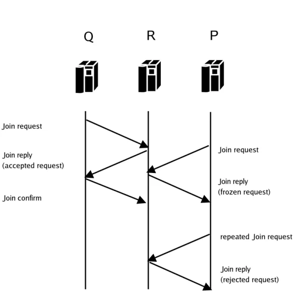
2.5.6.3 Join procedure
Unlike discovery procedure the join one leads to resource allocation and must be reliable in order to avoid resource wasting. Moreover it involves both client side functionalities and server-side ones.
Q node identifies the parent candidate node, R, it sends a join request to it,
figure 2.13, and starts the timeoutjoin countdown. If the timeoutjoin expires
without any R reply the request will be repeated.
R receives the request, evaluates the Q child metric and always sends a join reply. The join reply message can be
accept reply if R can immediately allocate outgoing resources. Moreover
R start immediately the timeoutjoin reply countdown.
refuse reply if Q child metric values is smaller than the R child node
small-est metric one
freeze reply if R can not immediately allocate outgoing resources (no
re-sources available or is performing another join) and the Q child metric are larger than the smallest one of the current R child nodes.
Q becomes a frozen child node in the R locale image. If the amount of frozen child node overcomes the maximum allowable child amount, R sends a refuse reply message to the worst frozen child node.
Q receives the R join reply and changes the R state characterization from parent candidate node to, respectively,
Fig. 2.13: Join phase signaling, R accept the Q request and freeze the P request until the Join phase with Q is terminated.
accept reply – parent node and it sends a join confirm message to R. The join confirm message can be used to reset the join procedure (neg-ative confirm). For example Q can send a neg(neg-ative confirm message if the R attributes are changed between the discovery procedure and the join one and they become not interestings for Q.
refuse reply – unknown node therefore Q selects a different parent
didate node and repeats the join procedure. If there is no parent can-didate node Q repeats the discovery procedure
freeze reply – parent candidate (the state does not change). Q waits
for the timeoutwaiting expiration and repeats the join procedure to R.
Moreover if the attributes of R will change (the parent metric will decrease) between the discovery procedure and the new join one Q selects another parent candidate node. Eventually, if R sends a second accept reply message, Q will reply with a negative join confirm message.
If the join confirm message is not received before the timeoutjoin reply
expi-ration, R sends a new accept reply message and reset the timeout.
At the join confirm reception R allocates the requested resources, i.e., starts to forward the requested content to Q. Obviously Q becomes an R child node.
Resources allocation have to be atomic procedure hence each join procedure has to be completed before a new one can begin. Moreover the current join procedure can not be stopped by external messages.
At the join procedure end, if frozen nodes exist (brown flow of picture 2.10), R evaluates the larger child metric of the current frozen child nodes and, if it is larger than the smallest one of the current R child nodes, it performs a new join procedure with this new joining child peer.
R sends accept reply message to the best frozen node and this peer can immediately send a join confirm message. Otherwise, if the best frozen child metric value is smaller than the smallest current child node one, R flushes all the frozen node by sending them a refuse reply.
In the hypothesis of a negligible packet loss the client side of the join
proce-dure requires a time period Tjoin that can be upper bounded by
Tjoin ≤ 3 · RT T + (nchild− 1) ∗ Treject ∼= (nchild− 1) ∗ Treject (2.3)
The worst situation in order to join to R is when R can not immediately
allocates resources and R has got (nchild− 1), i.e., the maximum amount of
Nevertheless the time required in order to perform the procedure with a peer that can accept immediately the request is
Tjoin = RT T (2.4)
A more accurate time estimation is calculated on section 2.7.
2.5.6.4 Reject procedure
Reject procedure is executed if a parent node has to relocate outgoing re-sources in order to accept a joining child node whose child metric is larger than the smaller child node one.
Like the join procedure reject one leads to resource management and hence it should be a reliable procedure.
This is a typical situation: R receives a request from Q; Q child metric is larger than the smaller R child node one, hence S, the worst R child node, has to be replaced by Q. R set the Q state to frozen child and set S state as a rejected child.
Soft handover policy imposes that the R reallocation resources have to follow a successful S new parent node search.
In order to increase packet loss resiliency R periodically sends a reject request message until S will reply to it.
At the reject request message reception, S set R state to bad parent node and begins a parent search.
Like join procedure the reject one is performed both on server side (Reject macro states of figure 2.9) that in client side (figure 2.6). In the server side flows reject procedure is atomic and can not be stopped by any external messages. On the client-side receiving a reject request message produces a transition toward basic flow (the new parent search will be executed with the higher priority).
At the end of parent node search S sends a reject reply message to R and set R state to unknown node. At the message reception R reallocates the resources dedicated to S and completes the join procedure with its best frozen child (the best one is not necessarily the first come node).
Moreover the reject reply message can be used to notify to the current parent node the success of an optimization procedure (deallocate loop in figure 2.9). Node that migrates to another parent node and join to it has to notify to the previous parent to deallocate its outgoing resources. This message should be sent using a reject reply one.
In the hypothesis of a negligible packet loss the client side execution of the
reject procedure requires a time period Treject that can estimated as
Treject= Tlock + Tdiscovery + Tjoin+ RT T (2.5)
In order to complete the reply procedure a node has to find a new parent and it has to complete successfully a new join. This time period involves the execution of other procedures (Lick, Discovery, Join). A more accurate estimation of the required time is calculated on section 2.7.
2.5.6.5 Lock - Unlock procedure
In order to avoid creation of peer loop sequences each discovery and join procedures don’t start until all the peer in the subtree are inhibited to accept join request. In figure 2.14 is depicted a possible loop generation due to unlocke subtree and contemporary node migration.
Each peer knows only the peers that communicate directly with it (neighbor nodes) and can not be able to previews that other peers will try to complete successfully a join procedure with nodes in the own sub-tree.
Lock and unlock procedures can be driven by the peer itself or by an ancestor node. The loop avoidance execution flow involves both the client side and the server side peer execution flows.
Lock and unlock procedure should be reliable and lock or unlock requests are sent to respectively unlocked and locked child until all the child nodes reach the requested state.
A peer sends a reply to its parent node only if whose child nodes are all locked or all unlocked. In picture 2.15 this behavior is depicted.
Request and reply messages are propagated across subtree with this paradigm until the requests reach the leaf nodes and the replies come back to the peer that has started the procedure.
In figure 2.15, in the hypothesis that RTT are the same between each couple of peer and that each peer immediately replies or immediately forwards the request to its own child nodes, the process can be completed in a RT T amount related to the tree level of the P 1 node subtree.
In the hypothesis of a negligible packet loss the lock (or unlock) procedure
requires a time period Tlock that can estimated as
Tlock(l) = RT T · l (2.6)
where l is the amount of level of the distribution sub-tree whose root is the peer that begins the lock procedure.
P1
P2
(1)P3
(1) (6)P4
(2) (4)P5
(2)P6
(2) (5)P7
(3) (3) (3) (4)Fig. 2.15: lock or unlock paradigm
If a node receives a lock request during the execution of the join procedure it will reply only after the conclusion of the current join. This behavior leads
to takes into account of an additive delay value in the range (0, Tjoin), but
also it allows to stop the lock request propagation into the tree section, i.e., a joining node subtree is always locked.
However the following upper bound can be written
Tlock(l) ≤ RT T · (l + 1) (2.7)
2.5.6.6 Optimizing procedure
The optimizing procedure is performed in order to find abetter position into
the P3P tree structure. The procedure starts at the timeoutsleeping expiration
that will be reset at the reception of each message that is not used in the
automatic recovery procedure. timeoutsleeping
• is initialized at each unlocking procedure at a value that decreases as long tree position level increases.
These strategies allows to realize a stable mechanism that promotes migra-tions of peer far from the root node.
The optimization procedure is essentially a client-side routine that triggers a sequence of lock-discovery-join procedure executed with lower priority (green flow on figure 2.6)
2.5.6.7 Recovery procedure
The recovery procedure is periodically executed by each peer in order to evaluate the neighbor node conditions. Each peer begins a three way hand-shake with its own parent node and at the end of this handhand-shake, if the parent node is running, it will estimate the RTT between itself and the parent node. Thanks to the third way message each parent node can also estimates the RTT between itself and its child nodes.
If parent node does not reply for a time period longer than timeoutdeadit will
be considered a failed node and a new parent search is started (basic flow on figure 2.6). Moreover if any messages are not received from a child peer for a
timeoutdead period the child node will be considered down and the reserved
resources will be free, see figure 2.11 on section 2.5.5.
2.5.7 Tree Management Protocol: initializing and updating node
references
In order to evaluate child metric and parent metric each node has to publish its own attributes. Some characteristics are decided autonomously by the peer but other ones are related to the position into each distribution tree structure or to the amount of neighbor nodes.
Each peer decides autonomously
• the total outgoing bandwidth and how this can be partitioned across the distribution trees in order to promote a distribution tree. Each node decides how many child nodes can be provided in each tree. • which distribution tree will be joined or not.
Nevertheless each node decides all the other attributes following the tree management protocol rules. In detail each node updates
• its own level, i.e., the amount of peer between the node itself and the tree root in each tree.
• the sequence of ancestor node in each tree
• the round trip time between itself and the neighbor nodes. All this second set of attributes have to be continuously updated.
In each outgoing P3P messages each node attaches all its own current at-tributes and all the nodes that receive these messages can learn other nodes characteristics.
If an executed procedure leads to resources management, the attributes will change accordingly. This change are related only to the peer that performs the procedure and has not to be propagated.
Instead, if the executed procedure leads to a migration into the tree structure, the attribute change has to be propagated into the peer sub-tree. Locking the subtree ensures that wrong attributes could not be sent away to the subtree and, during the unlocking procedure, the new attributes can be updated thanks to the unlocking request messages that are sent by parent nodes.
2.6
Software implementation
P3P multimedia stream management and signalation are written in C++. Standard C++ does not support multi threading execution and hence non standard libraries have been used: Boost C++ libraries, [13].
Boost libraries are intended to be widely useful and usable across a broad spectrum of applications. Ten Boost libraries are already included in the C++ Standards Committee’s Library Technical Report (TR1) and will be in the new C++0x Standard now being finalized. C++0x will also include several more Boost libraries in addition to those from TR1. More Boost libraries are proposed for TR2.
P3P is composed by 2 UDP Socket, RTPSocket and ControlSocket and the following resources shared by 5 different threads:
TargetList Is the collection of the current child nodes grouped by
distribu-tion tree
IncomingControlQueue Is the incoming queue of P3P signalation
OutgoingControlQueue Is the outgoing queue of RTCP messages P3P signalation messages
P3Pcore Is the real core of the P3P software: it contains all the peer states,
all the neighbors information and all the peer attributes The task of each thread is the following
RTP Management This thread manages the incoming RTP flows and also
sends the received packets to all the other peers that are identified as child node in the received packet distribution tree. It reads the RTP streams from RTPSocket, neighbor addresses from TargetList and then it forwards the packets using RTPSocket.
RTCP and Control Receiver This thread reads the P3P incoming
mes-sages and the incoming RTCP mesmes-sages from ControlSocket. Moreover it pushes P3P messages in the IncomingControlQueue and RTCP pack-ets in the OutgoingControlQueue.
RTCP and Control Sender This thread reads P3P messages or RTCP
messages from OutgoingControlQueue and it pushes them in the Con-trolSocket reading the new destination addresses from TargetList.
Asynchronous Logic This thread reads incoming P3P packets from
In-comingControlQueue and it manages them by following the P3P man-agement protocol rules. It modifies the Peer state, P3Pcore, and it updates TargetList
Synchronous Logic This thread periodically checks timeout expiration or
scheduled procedure execution. As the previous thread it modifies the Peer state, P3Pcore, and it updates TargetList
In figure 2.16 the interactions between sockets, threads, and shared resources are depicted.
2.6.1 P3P packet header
P3P messages are built on top of UDP header. In figure 2.17 the P3P message header is depicted
C (mandatory), 2 bits Code field distinguishes between RTP/RTCP
RTPSocket
ControlSocket
RTP Management RTCP and Control Receiver
IncomingControlQueue
OutgoingControlQueue
RTCP and Control Sender
Asynchronous Logic
TargetList
P3Pcore
Synchronous Logic
OrigAddr
OrigAddr
C Type
TreeID MaxC CurC Level
Ancestor Unused
Fig. 2.17: P3P message header
Type (mandatory), 6 bits Type field permits to identify the type of P3P
message (Discovery Request, Join Accept reply, . . . ).
TreeId (mandatory), 16 bits Identifier of the received P3P message
distri-bution tree.
MaxC (mandatory), 4 bits The maximum allowable child nodes amount in
the identified distribution tree.
CurC (mandatory), 4 bits The current child nodes amount in the identified
distribution tree
Level (mandatory), 8 bits The current nodes amount between the peer and
the root tree node.
Ancestor (mandatory), 32 bits Product of the nodes identifier of the peers
between the node itself and the root tree node, ancestor node. Each node is identified by a prime number. This field allows to identify if a node is or not an ancestor node
OrigAddr (optional), 48 bits Address of the peer that begins the discovery
procedure. It is used in order to send a discovery reply directly to the node that originates the procedure. This field is not mandatory: it makes sense only if field Type indicates a Discovery request message.
2.6.2 RTP and RTCP packet management
P3P has to tag each RTP or RTCP packet as belonging to a single distribution tree identified by a 16 bits identifier. RTP packet can be extended with the aid of RTP header extension, [14], depicted in figure 2.18. If the X bit in the RTP header is set to one, a variable-length header extension is appended to the RTP header, following the CSRC list if present. The header extension contains a 16-bit length field that counts the number of 32-bit words in the
Profile lenght
header extension
...
Fig. 2.18: RTP header extension
extension, excluding the four-octet extension header (therefore zero is a valid length). Only a single extension may be appended to the RTP data header. Therefore P3P can tag each RTP packet setting X bit in the RTP header and adding a 0 word RTP extension in which the field profile contains the distribution tree identifier and the field length is set to 0.
2.7
Connection time analysis
In section 2.5.6 the time required in order to accomplish each analyzed proce-dure is estimated in equations 2.2, 2.4, 2.5, 2.7. Nevertheless some proceproce-dure can require the execution of another procedures and also requires interactions with other nodes that are probably performing other procedures.
Therefore a tight overall time estimation can not be reduced to the sum of each single execution time over the sequence of required procedures (at least because a deterministic sequence does not exist).
The time period required to connect to a parent peer is pivotal in all the following situation:
• at the first connection to each P3P distribution tree (P3P client side) • after a parent node failure detection (P3P client-side)
• after the first reject request message reception (P3P client side)
• after an acceptable join request if the available resources are exhausted (P3P server side)
Nevertheless connection time involves also the optimization procedure dura-tion and each ancestor node driven lock phase.
Init
CL_0
p0
CL_1
p1
CL_2
p2
CL_3
p3
CL_4
p4
Discovery
1
1
1
1
1
pd
Join
1-pd qj
Join_Fr
pj
Connected
1-pj-qj
qjf
pjf
1-pjf-qjf
1
Fig. 2.19: absorbing Markov chain exploited in order to estimate the average