Titolo
POST-TEST ANALYSIS OF SHRT45R TRANSIENT
PERFORMED ON THE EBR-II FR
Descrittori
Tipologia del documento: Rapporto Tecnico
Collocazione contrattuale: Accordo di programma ENEA-MSE su sicurezza nucleare e
reattori di IV generazione
Argomenti trattati: Reattori nucleari veloci, Termoidraulica dei reattori nucleari, Sicurezza nucleare, Analisi incidentale
Sommario
Il report rappresenta un contributo all’analisi numerica di scenari operativi e incidentali e consiste nella messa a punto, nell’applicazione e nella validazione di un approccio e di modelli per analisi di sicurezza di reattori veloci di IV generazione. L’attività è svolta in sinergia con International Coordinated Research Project (CRP) on EBR-II Shutdown Heat Removal Tests promosso dall’IAEA. L’attività, di lungo respiro, è multi-physics e multi-scale e trarrà beneficio dalla disponibilità di dati sperimentali misurati in reattore durante l’esecuzione di test sperimentali: protected (SHRT-17) ed unprotected (SHRT-45r) loss of flow nel reattore americano di ricerca EBR-II. L’attività nel suo complesso richiede uno sforzo sinergico di differenti competenze tecniche, dalla fisica del reattore, alla termoidraulica di sistema, alla fluidodinamica computazionale, alla termomeccanica del fuel.
Il documento presenta le analisi di neutronica previste nell’ambito dell’attività, finalizzate prevalentemente alla valutazione dei coefficienti di reattività dei due test sperimentali (codici ERANOS e MONTECARLO) e alla simulazione del transitorio SHRT-45r con la cinetica neutronica tridimensionale (codice PHYSICS). Nel report vengono descritti i codici utilizzati e i modelli MCNP e SCALE/PHYSICS. I modelli descritti sono stati utilizzati per calcolare la frazione di neutroni ritardati e i quattro coefficienti di reattività (doppler, densità del liquido di raffreddamento, di dilatazione assiale, di espansione radiale). Infine, si riporta il fattore di forma radiale e l’errore relativo con i dati di specifica.
Note: Autori:
P. Balestra, E. Martelli, F. Giannetti, G. Caruso, A. Naviglio (CIRTEN-UNIROMA1) A. Del Nevo, C. Parisi, (ENEA)
Copia n. In carico a:
1 NOME
FIRMA
0 EMISSIONE 26/09/16 NOME A. Del Nevo M. Tarantino M. Tarantino
FIRMA
S
UMMARYThe present report is a contribution to the “Numerical analysis of operational scenarios and incidental” activity, that consists in the development, application and validation of approach and models for safety analysis of liquid metal Gen. IV reactors. The activity, developed in the framework of the International Coordinated Research Project (CRP) on EBR-II Shutdown Heat Removal tests promoted by IAEA, is multi-physics and multi-scale and will require the synergistic effort of different technical skills.
The report presents the ENEA neutronic tools used to develop the deterministic and stochastic EBR-II models, providing a description of the upgrades in the MCNP and SCALE/PHISICS modeling. The eigenvalue, delayed neutron fraction, and four reactivity coefficients (doppler, coolant density, axial expansion, radial expansion) are calculated using the final models. Finally the radial power shape factor and the relative error with the specification data are presented.
L
IST OF CONTENTSSUMMARY ... 3
LIST OF FIGURES ... 5
LIST OF TABLES ... 6
LIST OF ABBREVIATIONS ... 7
EBR-II PHISICS NEUTRONIC MODELLING ... 8
1
Neutronic codes description ... 81.1 EBR II broad-group nodal XSec library generation ... 8
1.2 Neutronic models description ... 12
1.3 Neutronic Results ... 14
1.4 Conclusive remarks and follow up ... 16
1.5
LIST OF REFERENCES ... 17
L
IST OF FIGURESFig. 1 – EBR-II SHRT45 full Core subassemblies map. ... 9
Fig. 2 – SCALE Driver Fuel S/A & half worth Driver S/A neutronic SCALE models... 10
Fig. 3 – SCALE MARK-IIS and CR Absorbing zone ... 10
Fig. 4 – SCALE Dummy S/A model. ... 11
Fig. 5 – SCALE Top Bottom and Radial Reflector models. ... 11
Fig. 6 – EBR- II PHISICS 3D neutronic model radial view. ... 12
Fig. 7 – Detail of core modelling – Driver / SS reflector interface. ... 13
Fig. 8 – Top and Bottom Reflector Modelling – S/A Steel Plugs. ... 13
Fig. 9 – PHISICS HFP DIM. model radial power shape factor and relative error. ... 15
Fig. 10 – PHISICS 3D model fast flux... 15
L
IST OF TABLESTab. 1 – ERANOS 33 energy group structure in [7] ... 9 Tab. 2 – PHISICS, MCNP Results. ... 14
L
IST OF ABBREVIATIONSBC Boundary Condition
CR Control Rod
INL Idaho National Laboratory
INSTANT Intelligent Nodal and Semi-structured Treatment for Advanced Neutron Transport NRC Nuclear Regulatory Commission
ORNL Oak Ridge National Laboratory
PHISICS Parallel and Highly Innovative Simulation for INL Code System
S/A Sub-Assembly
EBR-II
PHISICS
N
EUTRONICM
ODELLING1
Neutronic codes description 1.1
The EBR II 3D neutronic model was built using the advanced neutronic simulation code “Parallel and Highly Innovative Simulation for INL Code System” (PHISICS) [1] developed by the Idaho National Laboratory (INL). This code was chosen because has many required features which are not included in the default RELAP5-3D© nodal code NESTLE, for the simulation of a fast neutron system like EBR II. The PHISICS nodal solver, “Intelligent Nodal and Semi-Structured Treatment for Advanced Neutron Transport” (INSTANT) [2] allow to use transport or diffusion approximation and the number of energy groups is limited only by the hardware capabilities. For the angular discretization is possible to use up to 33 orders, and several nodes geometry are available such as Cartesian 2/3D, Hexagonal 2/3D, Triangular and Wedges. This powerful tool is coupled with RELAP5-3D©, to generate a state of the art software platform to perform safety analysis on the existent LWR fleet as the analysis of advanced reactor designs with an unlimited degree of accuracy. This code is compiled on “Falcon” and “Fission” HPC resources which are provided by the INL through a remote account.
The reference tool chosen to produce the EBR II XSec library is SCALE 6.1.2 [3] developed by “Oak Ridge National Laboratory” (ORNL) under contract with the “U.S. Nuclear Regulatory Commission” (NRC). In particular to produce the XSec library the SCALE control module TRITON and the related 2D deterministic transport code for lattice calculation “NEWT” are used. Because EBR II is a fast neutron system use the 44-group XSec library derived using a thermal weighting spectra from the ENDF/B-V is not recommended, therefore the 238-group XSec library based on the ENDF/B-VII was used, as recommended in [4]. For the self-shielding calculations, the CENTRM module was used. CENTRM calculates problem-dependent, group-averaged cross section, using as weight the flux calculated by solving the 1D Boltzmann transport equation with continuous-energy XSec library.
To generate a high fidelity 3D reference solution, the MCNP6TM code has been used. MCNP6TM is a general purpose, continuous-energy, generalized-geometry, time-dependent Monte Carlo radiation-transport code designed to track many particle types over broad ranges of energies [5]. The code main capability is to calculate keff eigenvalues for fissile systems. It is also able to perform
material burnup and delayed particle production calculation. Pointwise cross-section data are used. For neutrons, all reactions given in a particular cross-section evaluation (such as ENDF/B-VII) are accounted for. Thermal neutrons are described by both the free gas and S(α,β) models. A flexible tally structure allows calculation of important parameters such as neutron flux distribution and fluences.
EBR II broad-group nodal XSec library generation 1.2
NEWT calculate the flux solving the 2D transport equation using 238 energy group, after that it collapses the XSec in the space and in the energy dominions using the obtained flux solution. The result of each calculation is one set of XSec for each broad-group. Generally, for the LWR the XSec are collapsed in only two group: the thermal and the fast group. For a fast reactor in which the most of fission events occur out of the thermal range a more detailed energy mesh is necessary. For the present work the 33 energy group structure used in the ERANOS code [6] visible in Tab. 1 is adopted, since this code is widely validated for the fast spectrum reactors.
Energy group Upper Energy (eV) Energy group Upper Energy (eV) 1 1.96E+07 18 3.35E+03 2 1.00E+07 19 2.03E+03 3 6.07E+06 20 1.23E+03 4 3.68E+06 21 7.49E+02 5 2.23E+06 22 4.54E+02 6 1.35E+06 23 3.04E+02 7 8.21E+05 24 1.49E+02 8 4.98E+05 25 9.17E+01 9 3.02E+05 26 6.79E+01 10 1.83E+05 27 4.02E+01 11 1.11E+05 28 2.26E+01 12 6.74E+04 29 1.37E+01 13 4.09E+04 30 8.32E+00 14 2.48E+04 31 4.00E+00 15 1.50E+04 32 5.40E-01 16 9.12E+03 33 1.00E-01 17 5.53E+03
Tab. 1 – ERANOS 33 energy group structure in [7]
Since EBR II has a lot of sub-assemblies (S/A) with different geometry as visible in in Fig. 1 (i.e. S/A with dummy rods, experimental S/A, Control rods), many 2D SCALE models were used to calculate the Xsec for the different S/A.
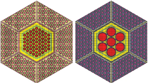
The core 97 fuel S/A have a specific burnup, detailed at three different axial levels. Thus an overall 291 different compositions are used by the benchmark organizer for characterizing the core status. Analyzing the composition database, it is possible to notice that some S/A with the same geometry are almost identical, and the error produced using an average composition for both the S/A is negligible. Using a specific threshold on the compositions the 97 different S/A can be reduced to only 25, thus resulting in just 75 compositions. E.g., the driver and half worth driver S/A MARKIIA models are visible in Fig. 2. These two models have been used to calculate the 54 homogenized XSec of the S/A with such geometry.
Fig. 2 – SCALE Driver Fuel S/A & half worth Driver S/A neutronic SCALE models
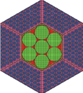
The Boundary Conditions (BC) used in the previous models are reflective BC. This is an approximation that is acceptable for modelling the MARK IIA S/A. This could be not true for the MARK-IIS S/A, which has less fuel pin and a thimble flow region. The Control Rods (CR) follower and one of the experimental S/A, have a MARK-IIS configuration (see Fig. 3). Inside the core this fuel is never surrounded by a S/A with the same geometry: the surrounding S/A could be a driver or a half worth driver, therefore a super-cell model has to be used. The same super-cell model but with absorber instead of fuel, (see Fig. 3) is used to calculate the XSec for the absorber part of the CR (seven B4C rods). The Absorbers are inside the active zone for almost 1.5 cm therefore them contribute cannot be neglected.
All the previous SCALE models were used to calculate the active fuel S/A but in the reactor there are also dummy S/A. The dummy S/A are made of AISI 304 steel and has a flow thimble region as the MARK-IIS but inside there are only seven AISI 304 rods as visible in Fig. 4. In this assembly there is not fissile material therefore a model similar to that of the absorber part of the CR has been used with some Driver S/A around it to supply the neutron source.
Fig. 4 – SCALE Dummy S/A model.
In the top and bottom reflector zones there are some blocks of steel with particular geometry which allow the flow of sodium to and from the active zone including also the final plenum of the fuel rods. Top and bottom reflectors XSec have been calculated using two simple models (see Fig. 5.) composed by the section of three S/A (almost half core) followed by the homogenized reflector materials. Two homogenized materials have been used for the top reflector model, the first to take into account the plenum zone of the fuel pins and the second for all the components above the fuel pins (upper shield sodium etc..).
The radial reflector and the blanket S/A constants have been calculated using a mini-core model composed by parts of the core itself, of three radial reflector rings and of the five blanket S/A rings. For all the Blanket S/A in the same ring the same averaged composition has been used, because their burnup is very similar.
Naturally this macro model has reflective boundary condition on the north south and west side and void condition on the left to take into account the leaks.
Neutronic models description 1.3
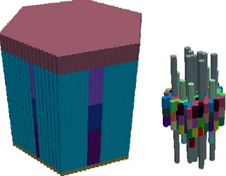
The 33-group XSec library (75 XSec for the Active fuel materials and 23 non fissile material) has been implemented in the 3D NK PHISICS model to perform three-dimensional core calculations. Fifteen rings of S/A plus the central one have been used, totaling 721 radial nodes. Axially, 32 meshes have been used with a variable length from 2 to 6 cm to take into account the extreme heterogeneity of the reactor. The full model is composed by 24072 neutronic nodes. Calculations were performed using the P1-diffusion approximation. In Fig. 6, the PHISICS full 3D NK model (left), and the inner core particular (right) are shown. No Gamma transport calculation has been taken into account.
Fig. 6 – EBR- II PHISICS 3D neutronic model radial view.
Monte Carlo static 3D NK calculations have been performed. The purpose of such activity was to obtain a detailed reference solution by evaluating neutronic parameters such as keff, reactivity
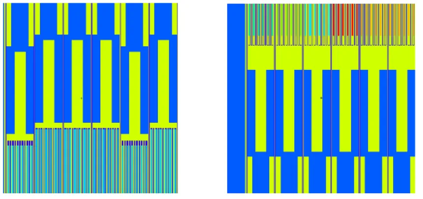
coefficients, power and flux distributions. These data were used for validating the multi-group cross section libraries and the PHISICS code deterministic model. The tool chosen for the static neutronic analysis is the Monte Carlo neutron transport code MCNP6, developed by Los Alamos National Laboratory (USA). EBR-II core is a quite heterogeneous system, requiring simulation of the different hexagonal S/A composing the core (61 S/A), the inner blanket (66 S/A) and the outer blanket (510 S/A), the control and Safety S/A, etc. MCNP6 allowed to perform a neutron transport simulation without introducing significant geometry simplifications. Detailed S/A modelling was performed, up to the pin level. A detailed view of the driver and of the core periphery (interface with the stainless steel reflector) is shown in Fig. 7. Lower and upper parts of the core were also modeled in detail, in order to take into account realistic axial neutron leakage effects. H-shaped cylindrical plugs and sodium volumes are shown in Fig. 8.
Fig. 7 – Detail of core modelling – Driver / SS reflector interface.
Fig. 8 – Top and Bottom Reflector Modelling – S/A Steel Plugs.
Materials temperatures and core dimensions of the MCNP model are for Hot Full Power Conditions (HFP) (MCNP6 HFP DIM. in Tab. 2). The same dimensions and material densities have been used to build the corresponding deterministic PHISICS model (PHISICS HFP DIM. In Tab. 2). In addition, in order to understand the influence of the material expansion from a Cold Zero Power condition, another deterministic model has been developed, considering the non-thermally expanded geometry (PHISICS CZP DIM. In Tab. 2).
Some reactivity feedbacks have been calculated using both the MCNP6 and the two PHISICS models, by perturbing the input parameters according to the specifications. To calculate the axial expansion coefficient, the number of mesh in the deterministic model has been preserved, changing only the mesh height. It should be noted that the temperature difference used for scaling the reactivity coefficients has been calculated:
deriving the equivalent temperature difference from the RELAP5-3D© sodium thermodynamic tables, when calculating the coolant density coefficient;
using a temperature difference corresponding to the 10% (axial) and 1% (radial) expansion of the fuel, when calculating the expansion coefficients.
Neutronic Results 1.4
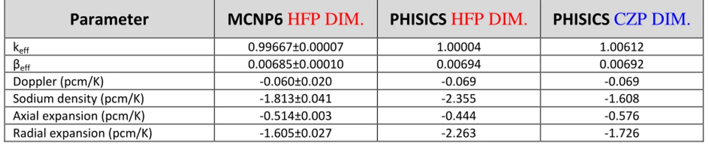
In Tab. 2 the NK calculation results have been reported. Comparison between MCNP6 and PHISICS models at HFP conditions shows acceptable agreement. The difference between the two keff is 337 pcm is a reasonable difference considering that the MCNP6 model is geometrically very
detailed and use continuous energy XSec while the PHISICS model is a nodal model and use 33 broad group XSec library. The βeff values and the Doppler coefficient of the deterministic model are
into the uncertainty range of the MCNP6 results. The deterministic model instead overestimates the sodium density and radial expansion coefficients. The difference between Monte Carlo and PHISICS for the perturbed cases used for the calculations of these coefficients is of the same magnitude of difference obtained for the HFP criticality calculations (around 300 pcm). The axial expansion coefficient is instead slightly underestimated.
Parameter MCNP6 HFP DIM. PHISICS HFP DIM. PHISICS CZP DIM.
keff 0.99667±0.00007 1.00004 1.00612 βeff 0.00685±0.00010 0.00694 0.00692 Doppler (pcm/K) -0.060±0.020 -0.069 -0.069 Sodium density (pcm/K) -1.813±0.041 -2.355 -1.608 Axial expansion (pcm/K) -0.514±0.003 -0.444 -0.576 Radial expansion (pcm/K) -1.605±0.027 -2.263 -1.726
Tab. 2 – PHISICS, MCNP Results.
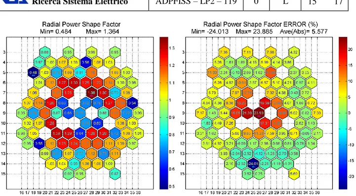
The results obtained using the deterministic model with CZP dimensions give back very different results. The core from a near critical configuration became almost prompt critical and the sodium density and radial expansion coefficients decrease of about the 40%. The axial expansion coefficient slightly increases. The Radial Power Shape and the relative error respect the reference solution in the specification is given in Fig. 9. The average absolute error is about the 6% but in some S/A, e.g. in the half worth Driver S/A, the error reaches about the 25%. This large discrepancy could be associated to a poor approximation for the boundary conditions (reflective boundary conditions) used when performing lattice calculations. This approximation is not valid especially when the driver S/A are bordering with several non-fuel S/A (e.g., in the central zone of the core).
Fig. 9 – PHISICS HFP DIM. model radial power shape factor and relative error.
In the next figures some 3D flux data are shown to observe the behavior of the neutrons in the system. In Fig. 10 the fast flux is represented. In this figure is possible to see how the fast flux is concentrated near the fissile material in the center and is practically absent in the reflector as expected. The maximum value is around 2.5E+15 that is completely consistent for a fast reactor. Is it also possible to distinguish a flux depressed zone corresponding to the CR.
Fig. 10 –PHISICS 3D model fast flux.
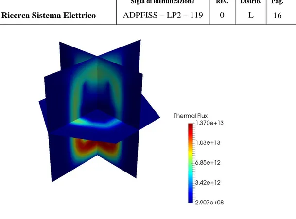
In Fig. 11 instead the thermal flux is represented. In this case the flux is concentrated completely outside the active zone in particular on the bottom because on the top the CR absorbers reduce the flux.
Fig. 11 – PHISICS 3D thermal group flux.
Conclusive remarks and follow up 1.5
A PHISICS standalone model was developed and the results are in good agreement with the Monte Carlo MCNP6 calculations. The Radial Power Shape and the relative error respect the reference solution are acceptable except on the half worth Driver S/A for which further investigations on the XSec generation process are needed.
L
IST OF REFERENCES[1] C. Rabiti, Y. Wang, G. Palmiotti, H. Hiruta, J. Cogliati e A. Alfonsi, Phisics: A New Reactor Physics Analysis Toolkit, 2525 North Fremont Avenue, Idaho Falls,, June,2011.
[2] Y. Wang, H. Zhang, R. Szilard e R. Martineau, Application of the INSTANT-HPS PN Transport Code to the C5G7 Benchmark Problem, Hollywood: presented at the American Nuclear Society (ANS) Summer meeting 2011, Idaho National Laboratory Report, June, 2011. [3] S. M. Bowman, "SCALE 6: comprehensive nuclear safety analysis code system", NUCLEAR TECHNOLOGY, Special Issue on the SCALE Nuclear Analysis Code System / Reactor Safety, Vol. 174, dx.doi.org/10.13182/NT10-163, May 2011.
[4] S. M. Bowman, R. Q. Wright, H. Taniuchi, and M. D. DeHart, "Validation of SCALE-4 criticality sequences using ENDF/B-V Data", presented at American Nuclear Society 1993 Topical Meeting on Physics and Methods in Criticality Safety, Nashville, Tennessee, US, September 19-23, 1993.
[5] J. T. Goorley et al., “Initial MCNP6 Release Overview – MCNP version 1.0”, LA-UR-13-22394 report, 2013.
[6] G. Rimpault, D. Plisson, J. Tommasi, and R. Jacqmin, "The ERANOS code and data system", Physor 2002 International Conference, Seoul, Korea, October 7-10, 2002.
[7] G. Bianchini, N. Burgio, M. Carta, V. Fabrizio, and L. Ricci, "Validazione del modulo di cinetica KIN3D di ERANOS.Analisi per i sistemi GODIVA e GUINEVERE", Rapporto Tecnico Accordo di programma ENEA-MSE: tema di ricerca "Nuovo nucleare da fissione", NNFISS-LP3-033, Rome, September, 2011.
![Tab. 1 – ERANOS 33 energy group structure in [7]](https://thumb-eu.123doks.com/thumbv2/123dokorg/5607537.68009/9.892.76.820.61.559/tab-eranos-energy-group-structure.webp)