Contents lists available atScienceDirect
Applied Thermal Engineering
journal homepage:www.elsevier.com/locate/apthermengExperimental and analytical procedure for the characterization of
innovative working fluids for power plants applications
G. Di Marcoberardino
a, C.M. Invernizzi
a, P. Iora
a, A. Ayub
a, D. Di Bona
c, P. Chiesa
b, M. Binotti
b,
G. Manzolini
b,⁎aUniversità di Brescia, Dipartimento di Ingegneria Meccanica e Industriale, via Branze, 38, 25123 Brescia, Italy bPolitecnico di Milano, Dipartimento di Energia, Via Lambruschini 4, 20156 Milano, Italy
cLEAP S.c.a r.l. - Laboratorio Energia e Ambiente Piacenza, Via Nino Bixio, 27/C, 29121 Piacenza, Italy
H I G H L I G H T S
•
A comprehensive procedure for innovative fluid identification is proposed.•
Thermodynamic properties must be assessed through Equation of state.•
Equation of State must be calibrated with VLE experiments for innovative fluids.•
Maximum operating fluid temperature is identified through thermal stability tests. A R T I C L E I N F OKeywords:
Power cycle definition Equation of state Thermal Stability Vapour liquid equilibrium Thermodynamic characterization
A B S T R A C T
In the last years, several fluids have been proposed to replace steam as working fluid in power cycle for con-verting thermal power into electricity. This paper describes the procedure to be adopted for the selection of any innovative fluid which can be even mixtures of fluids. The first step consists of the working fluid characterization in terms of thermodynamic properties through equations of state. The equations of state have to be calibrated on experimental Vapour-Liquid Equilibrium measurements while, in the second step, the maximum operating temperature is identified through thermal stability tests. Finally, the impact of the fluid thermodynamic prop-erties on the performance of the power cycle in which it is implemented must be assessed through modelling tools. In this work, the procedure is discussed for the mixture of CO2and C6F14as a potential working fluid for
gas thermodynamic cycles with liquid phase compression. Results of the application of this mixture in a closed cycle show the benefit of using a CO2/C6F14mixture which provides 3% points efficiency increase at 400 °C with
respect to the pure CO2together with a preliminary design of the expander.
1. Introduction
The thermodynamic conversion from heat to mechanical energy can be achieved exploiting either internal combustion gas cycles or external combustion cycles. The main advantage of the latter solution is its adaptability to a large variety of fuels and heat sources, as it is the case of the engines based on the well-known Rankine cycle[1]. The Rankine cycle was conceived with steam as working fluid and this solution still represents the reference technology for multi-MW power plants. Nonetheless, the (i) high critical temperature, (ii) small molar mass and (iii) rather simple molecular complexity of H2O, result in a quite
complicated configuration plant scheme and plant equipment design, particularly in case of the turbine and the high number of feedwater
heaters. This can be the case of the recovery of the medium–high temperature heat available from many industrial processes such as glass and ceramics factories, foundries and cement plants where ORCs with size lower than 1 MW becomes a more cost-effective choice rather than the classical steam cycles[2–4].
In addition, the growing exploitation of renewable energies is calling for engines operating in a wider spectrum of power output, maintaining the highest conversion efficiency compatible with the plant size and the temperature of the heat source. This requires the evalua-tion of thermodynamic soluevalua-tions alternative to the steam Rankine cycle, as well as the research of new working fluids, whose physical and thermodynamic properties allow a more cost-effective design of the power cycle given the thermal power and temperature of the heat
https://doi.org/10.1016/j.applthermaleng.2020.115513
Received 23 December 2019; Received in revised form 21 May 2020; Accepted 24 May 2020
⁎Corresponding author.
E-mail address:[email protected](G. Manzolini).
Available online 28 May 2020
1359-4311/ © 2020 The Author(s). Published by Elsevier Ltd. This is an open access article under the CC BY license (http://creativecommons.org/licenses/BY/4.0/).
supplied to the engine[5–7]. For low temperature applications, Organic Rankine Cycles (ORC) were introduced around 30 years ago[1] pro-viding more convenient commercial solutions than the steam Rankine cycle in particular at small scale applications (power output below 20–30 MW).
Nowadays, ORC research activity focuses on the selection and op-timization of the working fluid, considering various families such as organic and inorganic compounds as well as recently synthesized re-frigerants. For instance,[8]provides a systematic thermodynamic op-timization methodology for the selection of ORC fluids for heat re-covery from large internal combustion engines, while[9–11]present a working fluid screening applied to ORCs for the exergy recovery from regasification of liquefied natural gas and waste heat in refineries. It is worth noting that one limit of ORCs is that they cannot be adopted in high temperature applications because of the organic fluid decom-position.
As an alternative to Rankine cycles, closed Brayton cycles using ideal gases have been proposed in the recent past and are today con-sidered in niche applications at high temperature (800 °C)[12]. Closed Brayton cycles with real gases as working fluid are also considered in applications with reduced maximum temperature (below 600 °C) thanks to the relevant real gas effects in the compression phase which reduce the compression work [13]. In[14], the dependence of cycle performance and characteristics on the thermodynamic closed cycle location with respect to the limit curve are discussed. Brayton cycles exploiting condensation are presented in[15–17]. Real gas cycles using CO2were also extensively analysed in[18–20]. In[21], for example,
the authors examined the potential applicability of a carbon dioxide supercritical cycle of about 150 kW in advanced nuclear power systems and develop the design of many components. Supercritical carbon di-oxide cycles are today seriously reconsidered for high temperature applications in nuclear and solar plants[22–24].
The frontier of the research activity consists in the adoption of mixture of working fluids [25–27]. Within this context, the use of carbon dioxide mixtures as working fluids deserves to be investigated [28]. The identification of promising mixtures in concentrated solar power applications is the goal of the SCARABEUS project funded by the EU within the H2020 research programme.
Considering this evolution of thermal cycles from steam based to mixture-based fluids, a procedure for the selection of the optimal fluid must be adopted. This is even more relevant when the fluid properties are not available, which is typically the case of novel mixtures proposed as working fluids due to the lack of experimental data. Based on these considerations, this paper aims at defining a comprehensive procedure for selection and characterization of innovative working fluids for power plant applications. The procedure is firstly presented and then applied to the working mixture of carbon dioxide and perfluorohexane (CO2+ C6F14), a suitable working fluid for gas (Brayton) cycles with
compression in the liquid phase. As the procedure requires different steps both from experimental and modeling point of view, some of the experimental tests reported in this work summarise results developed in previous works on the mixture.
2. Working fluid desiderata and procedure identification The selection of the working fluid is crucial for an appropriate de-sign of the power plant. The level of the working temperatures, the characteristics of the heat source, the power size and the ambient conditions are the main parameters affecting the selection of the working fluid.
This section briefly summarizes the desiderata of an ideal working fluid so to identify the correct procedure for its selection in case of a Brayton cycle with condensation for a condensing temperature Tcondof
50 °C, and a corresponding reduced temperature (Tcond/Tc) of about
0.8–0.9:
•
As the compression is in liquid phase, the critical temperature should be around 100 °C;•
As the operating pressures affect directly the power density and the mechanical design, the critical pressure of the working fluid should be not too high;•
The molecular fluid complexity has a strong effect on the heat ca-pacities differences between the high-pressure and the low-pressure streams in the heat recuperator. So, for the peculiar thermodynamic cycles here considered, in general, a relatively high molecular complexity is appropriate;•
The heat exchanger sizes, especially the recuperator, can have a significant impact on the plant cost. Thus high heat transfer coeffi-cients are beneficial.Obviously, the ideal fluid which has all the above mentioned characteristics does not exist.
InTable 1, examples of potential pure working fluids with critical temperature of about 100 °C that can be adopted in a supercritical cycle are reported. The resulting condensing pressure which is rather high leads in these cases to power plants with high power density.
In addition to the thermodynamic properties, also safety and toxi-city aspects should be considered together with fluid cost and en-vironmental impact in terms of global warming and ozone depletion potential. Therefore, some of the fluids which can be considered in-teresting inTable 1, i.e. the highly toxic hydrogen sulphide, cannot be implemented in a real plant. On the other hand, perfluorocarbons are very expensive fluids and with a high global warming potential, but, they are not flammable, not toxic and show a high thermal stability [29].
The adoption of mixtures provides an additional opportunity in the selection of the working fluid: mixing two fluids is an effective method to change the critical point and thermodynamic properties according to the requested ambient conditions,[28,30]; the mixture will have the critical points in between the two pure fluids, depending on the con-centrations, hence this characteristic can be properly tuned by varying its composition. Recently, mixtures using carbon dioxide as the main component have been considered as working fluids in thermodynamic cycles[26,27]. The fluid to be added to the CO2must be miscible and
must improve the thermodynamic characteristic of CO2 with:(i) the
increase of critical temperature, (ii) the exploitation of the temperature glide on the condenser side and (iii) the design of the turbomachines modifying the compression ratio. For example, due to their substantial Table 1
Physical properties of some potential working fluids[33]. (°) values for 100 years time horizon. (*) relative to R11.
Chemical species Tc(°C) Pc(bar) MM (kg/kmol) Tb(°C) Global Warming Potential(°) Ozone Depletion Potential(*)
Hydrogen sulfide, H2S 100.25 89.63 34.08 −60.31 N.A. N.A.
R227ea, C3HF7 102.85 29.25 170.03 19.85 3350 0
R134a, C2H2F4 101.11 40.56 102.03 −26.11 1300 0
Octafluorocyclobutane, C4F8 115.22 27.78 200.03 −5.98 9540 0
Cyclopropane, C3H6 125.1 55.75 42.08 −32.81 86 0
immiscibility, mixture of carbon dioxide and water cannot be adopted [31], while fluids presented inTable 1can be considered as candidates for the CO2rich mixture.
Once preselected a working fluid or mixture with good potential-ities, a procedure to validate the fluid must be defined.
The procedure must include:
1. Definition of the thermodynamic properties and fluid behaviour at different pressure and temperatures including the two-phase region; A comprehensive characterization of the working fluid requires a reliable Equation of State (EoS) for the evaluation of its thermo-dynamic properties and the consequent assessment of the cycle performance as well as the design of the equipment (the pump or the compressor, the expander, the heat exchangers). Many EoS have been proposed in literature in the past years (see, for example, [32,33,34,35]). In general, the multi-parameter EoS have a good accuracy but require a deep validation and parameters optimization on experimental fluid volumetric behaviour or on Vapour-Liquid Equilibrium (VLE) data. In the selection of any new working fluid, one of the main goals is the identification of the bubble and dew lines; the adopted thermodynamic model has to correctly describe the Vapour-Liquid equilibria. From this point of view, the cubic equation of state (i.e. Peng Robinson or Redlich Kwong Soave) gives generally accurate results and can be easily extended to mixtures introducing the most appropriate mixing rules and calibrating the binary interaction parameters by experimental VLE data. In any case, the thermodynamic description of the critical region of the fluid is challenging and relatively inaccurate also when more com-plex models are adopted[36];
2. Thermal stability to identify the maximum operating temperature of the fluid before it starts substantially deteriorating;
the thermal stability is assessed through experimental tests where the fluid (or the mixture) are heated up to increasing temperatures for a predeterminate period of time. The fluid deterioration is as-sessed by comparing the behaviour of the fluids along curves at constant specific volume (isochoric lines) before and after thermal stress tests at high temperature, measuring two main thermo-dynamic properties, pressure and temperature. The deviations of the isochoric line with respect to the reference obtained from the virgin fluid, caused by the thermal decomposition, are evaluated both at high temperatures, during the thermal stress tests, and at tempera-ture close to ambient conditions;
3. Cycle design to assess the energy performance of the innovative fluid when integrated in a power block;
The performance of the working fluid when integrated in a power block is assessed through a cycle design performed either with commercial process simulation software or by developing in-house tools with proper EoS implemented. The purpose of this activity is the assessment of the net electric efficiency as function of the cycle maximum and minimum temperatures. Typical turbomachinery ef-ficiencies and heat exchangers minimum temperature differences are adopted in this phase;
4. Preliminary sizing of the main components;
The preliminary design of the main components (expander, pump, recuperative heat exchanger, condenser and the primary heat ex-changer) is relevant to assess the potentiality of the fluid as well as the cycle performance. The main characteristics of the components can be determined starting from the optimal conditions identified in the cycle design phase. In this phase, other thermodynamic prop-erties such as kinematic and dynamic viscosity and thermal con-ductivity must be derived from literature or from specific software. The following sections detail the procedure for the evaluation of an innovative working fluid applied to defined mixture of CO2and
per-fluorocarbons (see Table 2). This choice is justified by the relatively high thermal stability and good miscibility with CO2 of such
components. Moreover, the mixing of perfluorocarbons with carbon dioxide mitigates their detrimental high Global Warming Potential. Among the suggested perfluorocarbons, perfluorohexane (C6F14) is considered in this work due to its relatively high critical temperature and molecular complexity
3. Characterization of the working fluid 3.1. Equation of State definition
The study and the development of EoS is continuous and, in recent years, it has attracted considerable attentions. Generally speaking, an EoS should be easy to be extended and improved when experimental data become available. It should also be able to predict, with a rea-sonable precision, the thermodynamic behaviour outside the domain where experimental data are available. Although for carbon dioxide, the standard method to calculate its thermodynamic properties is now the NIST Reference Fluid Thermodynamic and Transport Properties Database (REFPROP)[37], this is not the case for other fluids as per-fluorocarbons. Therefore, another set of EoS must be adopted. In this work, the classic cubic Peng-Robinson equation[38]is considered for the purpose of a preliminary comparison between the fluids (pure and mixtures), given its good accuracy in the prediction of a fluid behaviour [26,27]. Furthermore, when applied to mixtures, it is able to predict also the retrograde condensation. The basic and simpler original ver-sion of the equation, without any volume translation and with the classical (van der Waals) mixing rules for mixtures is implemented. Certainly, more complex models can also be adopted which require additional steps for the calibration of the additional parameters in-cluded in the equation.
As a good description of VLE data is a reasonable assurance to an acceptable evaluation of the thermodynamic behaviour[39], we use the simple selected EoS for all the following calculations.
3.2. VLE experimental apparatus
The experimental VLE data on the CO2+ C6F14mixture, considered
in this paper and presented in[40], are collected by using the experi-mental apparatus designed and manufactured in 2012 by ARMINES and installed at LEAP laboratory. The test rig, schematically represented in Fig. 1and already described in[40,41], is based on a static-analytical method [42]. It allows measuring the thermodynamic properties of working fluids and mixtures for different fields of application.
Experiments to obtain VLE data for the binary system of CO2+ C6F14are performed by following this procedure described in
[40]. Isothermal measurements are usually performed during the tests. By removing fluid from the cell or adding CO2in it, different
equili-brium points at the same temperature can be evaluated. Temperature and pressure operating range of the apparatus extend respectively from −60 °C to 200 °C and from 10 bar to 199 bar.
At least five analyses are performed for each phase and the last is considered to correspond to the equilibrium values. Considering the uncertainty margin of all measuring devices, including the GC, it is possible to evaluate the total uncertainty of the mole fraction for both Table 2
Some physical properties of perfluorocarbons and CO2[33]. (°) values for
100 years time horizon. (*) relative to R11. Chemical species Tc(°C) Pc(bar) MM
(kg/ kmol) Global Warming Potential(°) Ozone Depletion Potential(*) Carbon dioxide, CO2 31.06 73.83 44.01 1 0 Perfluorobutane, C4F10 113.20 23.23 238.03 9200 0 Perfluorohexane, C6F14 176.40 18.02 338.04 7910 0 Perfluorobenzene, C6F6 243.58 32.75 186.06 N.A. 0
liquid and vapour phases[40]. 3.3. EoS and thermodynamic properties
The VLE experiments can be used to calibrate the coefficients of the EoS. In this work, Aspen Plus® v9.0 [43]is used to determine the coefficients ki,jfor the considered mixtures of carbon dioxide with the
selected perfluorocarbons starting from available experimental VLE data[40,44,45]; the calculated ki,jare shown inTable 3. Examples of
obtained VLE results and a comparison with the corresponding ex-perimental data are reported in Fig. 2 for the investigated mixture CO2+ C6F14.
In addition, when dealing with mixture of working fluids, it is useful to identify the critical point as function of the composition. Since the critical temperature and pressure for mixtures do not correspond to the maximum values on the saturation curve, a tool to calculate the actual critical point of binary mixtures has to be developed. In fact, this can be estimated by an EoS applying the Gibbs criteria[46]. A successful nu-merical method, based on the use of the Helmholtz free energy, was proposed in[47]and in[48]; this method was adapted to the cubic equation of state and expressed in a generalized non-linear system of equations with intensive variables. The solutions of this highly non-linear system are the critical temperature and the critical volume of the mixture.
The critical point code developed in this study is based on the ap-proach described in[48], and implemented in MATLAB version R2019a
with the help of INTLAB toolbox[49]. INTLAB toolbox is specifically designed for interval arithmetic for real and complex data and is compatible with MATLAB version R2016a and onwards. The efficient root finding capability of INTLAB is exploited to solve the non-linear system of equations of critical point. The code requires pure compo-nents critical points, molar composition of each component, acentric factors and binary interaction parameter corresponding to the con-sidered EoS as input information to compute the critical points of a binary mixture. In addition, the initial estimate of the solutions is also required. The code is capable to compute both stable and metastable critical points at given composition of any binary mixture without any initial guesses.
In Fig. 3, the P-T envelopes and the critical locus for a binary mixture of carbon dioxide and perfluorohexane are reported. It can be observed that adequate thermodynamic properties of the mixture can be obtained for instance with a CO2content of 0.75 (molar fraction),
resulting in a bubble pressure (at 50 °C) of about 55 bar and a tem-perature glide of about 70 °C.
4. Thermal stability of pure fluids and mixtures
The thermal stability analysis aims at the evaluation of the max-imum operating temperature range of the working fluid to be adopted in a power cycle. Experimental tests are carried out first on the two pure fluids, and then on the mixture.
The experimental apparatus consists of a cylinder of 75 cm3
(ma-terial: AISI 304L) containing the fluid to be analysed, a thermocouple (type K) and a pressure transmitter that cover a wide range of pressure from 1 to 50 bar and some block valves to charge and isolate the in-vestigated fluid. More details on the experimental apparatus together with the accuracy of the measurements are discussed in[50–52].
In this work, the thermal stability tests for both pure CO2and for the
mixture of CO2+ C6F14with CO2content of 80% are performed while
results of pure C6F14are collected from a previous experimental
cam-paign[53], where a different procedure and approach, suitable for pure Fig. 1. Schematic diagram of the experimental apparatus. More details of all its main components are described in[41].
Table 3
Binary interaction parameters k1,2= k2,1for the considered mixtures of carbon
dioxide (subscript 1) and some perfluorocarbons (subscript 2).
Chemical species in the CO2rich mixture k1,2= k2,1 Standard Deviation Perfluorobutane, C4F10 0.1011 0.0038
Perfluorohexane, C6F14 0.0176 0.0028 Perfluorobenzene, C6F6 0.0312 0.0181
fluids was implemented.
Carbon dioxide, supplied by Sol, has a purity of 99.99% while the perfluorohexane (CAS: 355-42-0) has been supplied by Alfa Aesar with a purity level higher than 98%. For all the tests, the mass of the sample fluid is defined on the requirement of keeping the system pressure below the safety value of 50 bar.
After charging the sample of fluid at temperature close to ambient conditions, the experimental procedure consists of a thermal stress in an electric oven at high temperatures for a typical time span of 80–100 h, followed by the measure of the isochoric line (or vapour pressure for pure C6F14) in a thermostatic bath. In particular, the experimental test
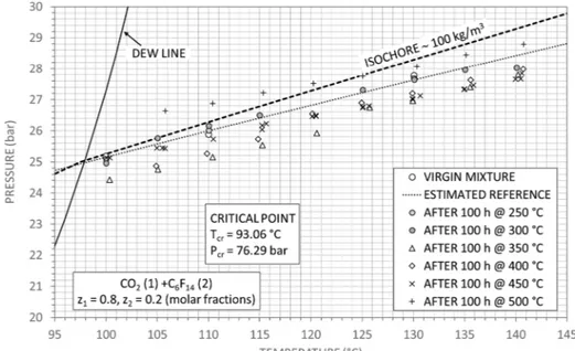
conditions of the investigated fluids are summarized inTable 4. Fig. 4shows the results of the thermal stability test for pure carbon dioxide where the reference p-T measurements correspond to the virgin fluid behaviour: the CO2density, equal to 32.7 kg/m3, is fixed during
the tests, and it is determined by the ratio of the weighted mass loaded in the circuit and the internal volume of the sample cylinder. The up-ward shift of the isochoric lines for the two tests at higher temperature
revealed fluid decomposition at 500 °C due to the well-known inter-action of the CO2with the stainless steel[54,17].
Even if a chemical analysis could be useful to have a full picture of the decomposition phenomenon, the numerical analysis of the p-T measurements, discussed below, is enough to identify a fluid degrada-tion signal.
The method proposed in this work lies on the study of the ther-modynamic behaviours of the working fluid from the variation of the van der Waals coefficients. The simpler equation of state, accounting qualitatively the real gas effects of a fluid, is the van der Waals equation [55]: = P RT V b a V m m2 (1)
where Vm(m3/kmol) is the molar volume ( =Vm V MM/ ), R (kJ/kmol K) is the gas constant and the coefficients a and b can be found for each substance from the following equations at the critical point.
Fig. 2. P-xy VLE results for the mixture of carbon dioxide and perfluorohexane at T = 40 °C. Circles are from experimental data reported in [40], crosses are from Aspen Plus® v9.0 database[43]. The uncertainties associated with temperatures and with pressures measurements (with coverage factor 2) are ± 0.08 °C and ± 0.06 MPa (maximum) re-spectively. The mean uncertainties in the measured molar fractions are about 4.0e-03 for xCO2, and 5.0e-04 for yCO2[40].
0 10 20 30 40 50 60 70 80 90 0 20 40 60 80 100 120 140 160 180 200 PR ES SU RE (ba r) TEMPERATURE (°C)
CARBON DIOXIDE (1) / PERFLUOROHEXANE (2)
z1= 0
z1= 1 z1= 0.75
z1= 0.25
CRITICAL LOCUS
= P a b 27 c 2 (2) = Vc 3b (3) = T a Rb 8 27 c (4)
The comparison of the estimated coefficients a, b and the molar mass (MM) from the regression of the experimental data (in the gas phase), starting from the virgin fluid isochoric line, and after each thermal stress test, can be representative of potential decomposition of the investigated fluid1. As a consequence of the thermal stress, the substance decomposes in a mixture of different unknown species that, for simplicity, is assumed as a pure fluid characterised by different coefficients a, b and MM.
Pure CO2case is discussed below as an example of the proposed
procedure. The corresponding parameters of the van der Waals equa-tion of state, obtained by the non-linear regression of the experimental values for a density equal to 32.7 kg/m3are reported inTable 5.
De-composition of the sample produces a variation of the isochoric lines and, as a consequence, of the parameters a, b and MM. These results can be assumed as an indirect indication of the extent of the decomposition. Moreover, starting from the obtained parameters, the isothermal compressibility kT, defined in Eq.5, can be used as a proper index to
highlight the impact of the thermal degradation on the power cycle. As shown inTable 6, after 200 h at 500 °C, the compressibility kTdecreases
by about 18% (at the same volume and temperature).
= = k V P V V a V RT V b 1 2 ( ) T m m T m 3 2 (5)
Regarding the pure perfluorohexane, a previous experimental campaign [53]revealed that C6F14 can be considered stable up to
350 °C, showing early signs of decomposition after the thermal stress test at 400 °C.
Finally, the reference isochoric and dew line for a mixture of carbon Table 4
Thermal stability tests conditions.
Fluid Isochoric line(a)/Vapour pressure(b) Thermal stress
T (°C) ΔTstep(°C) T (°C) ΔTstep(°C) Timestep(h)
(a)CO2 −20 ÷ 40 10 400–500 100 100
(b)C6F14[53] −20 ÷ 30 10 200–450 50 80
(a)CO2+ C6F14 10 ÷ 140 20 for T ≤ 100
5 for T > 100 250–500 50 100
Fig. 4. Results of p-T measurements for pure carbon dioxide at 500 °C.
Table 5
Parameters a, b and MM of the van der Waals equation of state for carbon dioxide for the thermal stability test at 500 °C.
a (MPa m6kmol−2) b (m3kmol−1) MM (kg kmol−1)
Virgin fluid 0.607 0.060 41.452
After 100 h 0.457 0.065 42.775
After 200 h 0.355 0.069 43.080
Table 6
The estimated isothermal compressibility kTof carbon dioxide at 10 °C for the
virgin and the decomposed fluid using the van der Waals coefficients and MM of Table 5.
1/kT(MPa) u(kT) (MPa)
Virgin fluid 1.292 0.021
After 100 h 1.458 0.015
After 200 h 1.582 0.012
1Since the van der Waals fluid is not a real fluid, the coefficients a, b and MM
dioxide and perfluorohexane, with molar fractions of 80% and 20% respectively, is shown in Fig. 5. The virgin fluid measurements are along mixture density value of 99.4 kg/m3, in the gas phase.
Further-more, measured p-T points after each thermal stress are represented. The best fit of the experimental values using the van der Waals equation of state, according to the procedure previously described, gives the values inTable 7, assuming a pure fluid behaviour of the mixture, while Table 8shows the resulting isothermal compressibility kTat different
temperature. Since measurements at 250 °C and 300 °C are in agree-ment with the fresh mixture, the values were included for the calcula-tion of the virgin mixture parameters.
Although the van der Waals parameters are slightly different after the thermal stress tests at 350 °C and 400 °C, the mixture can be con-sidered thermally stable up to 400 °C: this behaviour is also confirmed from the parameter kT. Decomposition phenomena occur from 450 °C
where not only the isothermal compressibility increases by more than 50% with respect to the virgin mixture but also a strong deviation of the van der Waals parameters from initial values can be observed.
5. Modelling of the thermodynamic cycle
Performance of a simple recuperative cycle working with the CO2+ C6F14mixture are investigated in Aspen Plus® v9.0[43]. The
Peng-Robinson EoS[38]with the binary parameter defined inSection 3.3is adopted for all thermodynamic properties.
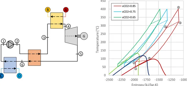
As shown inFig. 6, the power cycle consists of a compression step (from 1 to 2), followed by a pheating section (2–3), also called re-cuperator, and a primary heat exchanger (3–4), where the maximum operating temperature is achieved; afterwards, the working fluid is expanded in a turbine (4–5), cooled in the recuperator (5–6) and, fi-nally, in a dry cooler, also called condenser (6–1).
Table 9summarizes the main design parameters adopted for the cycle modelling. The minimum operating pressure is set by the minimum working temperature: a condensing cycle means that the compression step starts from saturated liquid phase, so the saturation pressure at 50 °C, for each mixture composition, is the minimum cycle pressure. The maximum temperature is the minimum between the thermal stability results and the heat source.
The turbomachinery components are modelled with isentropic ef-ficiency approach. Pressure drops in the heat exchangers are for sim-plicity neglected, even if they can be easily implemented. The typical pinch point of heat exchanger operating with gaseous-condensing phases is adopted in this preliminary analysis (10 °C). As the minimum temperature difference can occur inside the recuperative heat ex-changer, this parameter is named Minimum Internal Temperature Approach (MITA).
As the analysis is in relative terms (for example innovative fluid vs. CO2), and considering that the cycle design is not optimized to fully
exploit the potentialities of the new fluid, but as go/no-go stage gate for deeper investigations, the adoption of typical component performance and neglecting the pressure drop is reasonable in this phase.
Examples of the T-s (Temperature-Entropy) diagrams for three mixtures at different compositions are reported inFig. 6(right). The increasing of the C6F14 molar fraction leads to a high critical
tem-perature and an isentropic dew line. In parallel, the higher the CO2
concentration in the mixture, the higher is the temperature variation along the expansion.
The influence of different CO2+ C6F14mixture composition is
in-vestigated in terms of power cycle efficiency which is defined as: Fig. 5. Results of P-T measurements for the mixture CO2+ C6F14.
Table 7
Parameters a, b and MM of the van der Waals equation of state of the mixture carbon dioxide and perfluorohexane.
a (MPa m6kmol−2) b (m3kmol−1) MM (kg kmol−1)
Virgin mixture 0.818 0.086 102.4 350 °C 0.901 0.087 102.9 400 °C 0.924 0.088 101.0 450 °C 0.016 0.360 158.7 500 °C 0.004 0.584 176.1 Table 8
The estimated isothermal compressibility kT of carbon dioxide and
per-fluorohexane at 120 °C for the virgin and the decomposed mixture using the van der Waals coefficients and MM ofTable 7.
1/kT(MPa) u(kT) (MPa)
Virgin mixture 2.25 0.052
350 °C 2.08 0.054
400 °C 2.07 0.057
450 °C 3.43 0.122
= P P Q
cycle
turbine compressor
in cycle, (6)
where Pturbine- Pcompressoris the net electric power (Pnet) generated by the recuperative cycle and Qin,cycleis the thermal power input to the power cycle.
Fig. 7shows the power cycle efficiency as function of the mixture composition expressed in terms of CO2 molar fraction and the
max-imum cycle pressure. The highest power cycle efficiency (around 34%) is obtained for a C6F14molar fraction between 0.175 and 0.2. Notably
these efficiency values are significantly higher than those obtainable adopting CO2as pure fluid for a Brayton recompression cycle, as shown
inFig. 7. For instance, the recompression pure sCO2cycle[22,56]with
a minimum pressure of 100 bar and assumptions consistent with those
inTable 9results in a maximum cycle efficiency of about 31% obtained with turbine inlet pressure of 190 bar.
6. Preliminary considerations about heat exchangers and turbomachiniery design
Once confirmed the potentialities of the innovative fluid through the cycle design, some preliminary considerations about the compo-nents must be drawn to anticipate some critical aspects in the main components (i.e. low heat transfer coefficients, volumetric expansion ratios).
Between the supercritical cycle components, the turbine, the re-cuperative heat exchangers and the condenser play a key role. In this section, some notes about their preliminary design and a comparison between the cycle with pure CO2 and the innovative one with the
mixture CO2+ C6F14with a molar fraction of 80% of carbon dioxide
are discussed. The values used for the comparison, corresponds to the maximum cycle efficiency for both the cycle.
The cycle requires three different heat exchangers: the primary heat exchanger where the heat is transferred to the fluid, the condenser where the heat is rejected to the ambient and the recuperative heat exchanger where the fluid is preheated recovering heat from the turbine outlet flow. A detailed heat exchanger design requires the estimation of the fluid or mixture transport properties (i.e. molecular dynamics method is proposed in[57]while other methods are presented in[33]) and the definition of a certain geometry that require further analysis which are beyond the scope of this work. Even the bi-phase mixture behaviour in the condenser has to be explored in a dedicated study, considering that the mixture convective heat transfer coefficients in two-phase flow are basically lower than that of the pure fluids[58]. In particular, the effects of the relatively high condensation pressure, should be further investigated for trans-critical cycle.
In general, the primary heat exchanger and the condenser are based on shell-and-tube configuration, while the recuperator is typically based on a printed circuit heat exchanger (PCHE) configuration. The PCHE maximizes the surface to volume ratio hence minimizing the component volume/weight and it can tolerate the typical pressures of these applications. In literature there are several studies on PCHE for pure CO2 to rely on [22,23] which can be extended to CO2-based
mixtures.
As can be noted inTable 10, for the investigated mixture, the ex-changed thermal power in the recuperator is twice the thermal power G
C
D
A
B
1 2 3 4 5 6 0 50 100 150 200 250 300 350 400 450 -2500 -2250 -2000 -1750 -1500 -1250 -1000 Tem per at ur e (° C) Entropy (kJ/kg-K) xCO2=0.85 xCO2=0.75 xCO2=0.65 1 2 3 4 5 6Fig. 6. (left) schematic of a simple recuperative condensing supercritical cycle and (right) T-s diagrams of the simple recuperative condensing supercritical cycle for different fractions of CO2and C6F14. The dashed lines represent the inlet–outlet conditions of the recuperative heat exchanger. Thermodynamic properties of points
are reported inTable 10. Table 9
Power cycle assumptions.
Maximum temperature, °C 400
Minimum temperature, °C 50
Recuperator minimum internal temperature approach (MITA), °C 10
Turbine inlet pressure, bar 150–350
Compressor/Pump isentropic efficiency, % 0.85
Turbine efficiency, % 0.90 0.28 0.29 0.3 0.31 0.32 0.33 0.34 0.35 150 175 200 225 250 275 300 325 350 Maximum cycle pressure (bar)
0.75 0.775 0.8 0.825 0.875 Pure CO2 Cy cl e effici en cy (-)
Fig. 7. Cycle efficiency as function of the turbine inlet pressure for different molar fractions of CO2and C6F14and for pure sCO2recompression cycle.
input and more than three times higher than the exchanged thermal power in the condenser. This implies that the recuperator design will considerably affect the cycle capital cost. The resulting UArec/Pnetof the
recuperator (rec) is 0.36 K−1with a ratio of 6.4 between the exchanged
thermal power and the produced net power. These values are sig-nificantly lower than the corresponding ones for pure CO2which are
equal to 0.53 K−1and 13 respectively, meaning that the mixture would
require smaller surface areas per unit of net power.
The turbomachinery design can be performed adopting a pre-liminary approach based on the similarity rules and assuming the thermodynamic conditions determined in the cycle design step (see Table 10).
A preliminary sizing of the turbine can be developed assuming ideal turbine stages, without considering the traditional fluid-dynamic losses, resorting to the free-vortex theory and assuming a total admission. The rotational speed N can be selected assuming s andDs close to the usually accepted optimal values,[59], and a ratio h/D (where h is the mean blade height and D the mean diameter for the stage) in a rea-sonable range (0.025<h/D<0.4), compatibly with a small kinetic energy loss (below 10% of the Eulerian work).
An example of the preliminary results for the considered mixture are reported inTable 11 where the main characteristics of the resulting turbine stages are summarized. Although the two stages have almost the same dimensions, the higher molar mass of the mixture involves a lower peripheral speed. Fixing the rotor reaction degree equal to 0.5, the greater volumetric expansion ratio of the mixture case could have, as a consequence, an excessive flaring angle, compared to the pure CO2
case. For this reason, the reaction degree of the mixture has to be re-duced, resulting in this case with supersonic conditions for the nozzles. The turbines do not present particular critical issues in both cases: the final design, the final design solution could require more than one stage due to the relatively high temperature but this parameter depends also on the plant power size. For a complete evaluation of the design characteristics of the turbine, the different turbine losses have to be considered.
7. Conclusions
The exploitation of renewable energy sources and the possibility to recover heat from industrial processes call for the selection of new working fluids in power cycles. This paper presented the procedure for the identification of innovative working fluids to replace the more conventional steam and pure CO2for heat sources at relatively high
temperature (greater than 350–400 °C). The main rationale behind the adoption of an innovative fluid relies in the improvement of the con-version efficiency, reduction of the power block complexity and size, while keeping the same reliability.
Once the fluid or the mixture are selected, the procedure consists of (i) the identification and calibration of the thermodynamic properties of the innovative fluid through proper Equation of State with experi-mental Vapour-Liquid Equilibrium measurements, (ii) the identification of the maximum operating temperature through thermal stability tests, (iii) the assessment of the power cycle performance at different mixture compositions and (iv) the design of the main plant equipment parti-cularly focusing on the expander and the recuperative heat exchanger. The procedure is applied to a promising mixture of CO2+ C6F14
showing the potentialities of the mixture to replace pure CO2 as
working fluid: the cycle efficiency adopting the CO2+ C6F14mixture is
close to 34% assuming a maximum operating temperature of 400 °C which is 3–4% points higher than the performance of a recompression cycle implementing pure CO2. The preliminary evaluation of the
re-cuperator, and the turbine confirmed the potentiality of the in-vestigated mixture: the ratio UArec/Pnetresults about the 60% lower
than the corresponding value required by pure carbon dioxide and the design of the turbine is not particularly critical.
Some crucial aspects of the described general procedure are about thermal stability investigations, particularly critical and difficult to develop, but essential. In addition to thermal stability in a (relatively) inert environment, it could be also necessary to evaluate the fluid compatibility with the usual materials involved in the manufacture of the engine.
As the use of carbon dioxide mixtures (as here proved), at least for the specific considered application, is potentially beneficial from the thermodynamic point of view, and as the thermodynamic behaviour of mixtures are not easily predictable, measures of VLE are necessary. Many other topics have to be explored (for example the transport properties necessary for a detailed design of the heat exchangers), but certainly the thermodynamic evaluations and the thermochemical sta-bility are the most important in a preliminary study.
The final design of heat engines using new working fluids is de-manding, but the results here presented and discussed show that, at least from the thermodynamic point of view, there is room for sig-nificant improvements in the resulting efficiencies.
Declaration of Competing Interest
The authors declare that they have no known competing financial interests or personal relationships that could have appeared to influ-ence the work reported in this paper.
Acknowledgements
This paper is part of the SCARABEUS project that has received funding from the European Union’s Horizon 2020 research and in-novation programme under grant agreement No 814985.
References
[1] C.M. Invernizzi, Closed Power Cycles - Thermodynamic Fundamentals and Applications, Springer-Verlag, London, 2013.
[2] G. Manente, M. Costa, On the Conceptual Design of novel Supercritical CO2 Power Cycles for Waste Heat Recovery, Energies 13 (2020) 370,https://doi.org/10.3390/ Table 10
Thermodynamic properties of the mixture (CO280%mol, C6F1420%mol) with a
maximum pressure of 250 bar.(+)Enthalpy and entropy values are calculated
using stream 1 (saturated liquid) as reference state.
Stream T (°C) p (bar) h (kJ/kg)(+) s (J/kgK)(+) Vapour fraction
1 50 61.85 0 0 0 2 75.7 250 19.7 4.7 0 3 295.1 250 308.3 647.6 1 4 400 250 442.0 863.5 1 5 329.3 61.85 377.1 875.6 1 6 92.1 61.85 88.5 258.6 0.59 Table 11
Thermodynamic conditions assumed for the expander design and resulting preliminary stage design parameters.
Working fluid Pure CO2 80%CO2+ 20%C6F14
Assumptions
Initial expansion temperature (°C) 400 400 Initial expansion pressure (bar) 190 250 Final expansion pressure (bar) 100 62.5 Isentropic power (kW) 10,000 10,000 Preliminary estimated design parameters
Rotation speed (rpm) 20,000 15,000 Reaction degree at the mean diameter 0.5 0.25 Overall volume expansion ratio 1.673 3.587 Inlet volume flow rate (m3/s) 0.874 0.323
Tip diameter (cm) 33.5 28.9
Mean diameter (cm) 32.47 27.2
h/D 0.031 0.062
en13020370.
[3] R. Vescovo, E. Spagnoli, High Temperature ORC Systems, in: IV International Seminar on ORC Power Systems, ORC 2017, 13–15 September 2017, Milano, Italy. [4] Anonymous, Process heat in industry and commerce - Technology solutions for
waste heat utilisation and renewable provision, German Energy Agency, September, 2016.
[5] Luigi d'Amelio, L'impiego di vapori ad alto peso molecolare in piccole turbine, Industria Napoletana Arti Gra_che, Napoli, 1935.
[6] H. Tabor, L. Bronicki, Establishing Criteria for Fluids for Small Vapor Turbines, in: SAE National Transportation, Powerplant, and Fuels and Lubricants Meeting, number 931C, October 1964.
[7] G. Angelino, M. Gaia, E. Macchi, A review of Italian activity in the field of Organic Rankine Cycles, in: ORC - HP - Technology. Working fluid problems, volume VDI Berichte 539, Verein Deutscher Ingenieure, VDI Verlag, September 10–12 1984, pp. 465–482.
[8] R. Scaccabarozzi, M. Tavano, C.M. Invernizzi, E. Martelli, Comparison of working
fluids and cycle optimization for heat recovery ORCs from large internal
combus-tion engines, Energy 158 (2018) 396–416.
[9] H. Yu, D. Kim, T. Gundersen, A study of working fluids for Organic Rankine Cycles
(ORCs) operating across and below ambient temperature to utilize Liquefied
Natural Gas (LNG) cold energy, Energy 167 (2019) 730–739.
[10] C.M. Invernizzi, P. Iora, The exploitation of the physical exergy of liquid natural gas
by closed power thermodynamic cycles. An overview, Energy 105 (2016) (2015)
2–15.
[11] H. Yu, X. Feng, Y. Wang, L.T. Biegler, J. Eason, A systematic method to customize
an efficient organic Rankine cycle(ORC) to recover waste heat in refineries, Appl.
Energy 179 (2016) 302–315.
[12] H.U. Frutshi, Closed-Cycles Gas Turbines, ASME Press, Three Park Avenue, New York, NY 10016, 2005.
[13] E.G. Feher, The Supercritical Thermodynamic Power Cycle, in: Advances in Energy Coversion Engineering, volume 1967, Intersociety Energy Conversion Engineering Conference, August 13–17, United Engineering Center, 345 East 47th Street, New York, N.Y. 10017, The American Society of Mechanical Engineers, 1967. [14] C. Casci, G. Angelino, The Dependence of Power Cycles performance on Their
Location Relative to the Andrew Curve, in: ASME Gas Turbine Conference and Products Show 1969, number 69-GT-65, The American Society of Mechanical Engineers, March 9–13 1969.
[15] G. Angelino, Perspective for the Liquid Phase Compression Gas Turbine, Trans.
ASME, J. Eng. Power 89 (2) (1967) 229–237.
[16] G. Angelino, Liquid-Phase Compression Gas Turbine for Space Power Applications,
J. Spacecr. Rock. 4 (2) (1967) 188–194.
[17] G. Angelino, The Use of Liquid Natural Gas as Heat Sink for Power Cycles, Trans.
ASME, J. Eng. Power 100 (1) (1978) 169–177.
[18] G. Angelino, Carbon Dioxide Condensation Cycles for Power Production, Trans.
ASME, J. Eng. Power 90 (3) (1968) 287–295.
[19] G. Angelino, Real Gas Effects in Carbon Dioxide Cycles, in: ASME Gas Turbine Conference and Products Show 1969, number 69-GT-102, United Engineering Center, 345 East 47th Street, New York, N.Y. 10017, 1969, The American Society of Mechanical Engineers.
[20] D. Schmidt, Closed-Cycle CO2 Gas Turbine Power Plant, U.S. Patent 3 512 358, May 19th 1970.
[21] J.R. Hoffmann, E.G. Feher, 150 kWe Supercritical Closed Cycle System, Trans.
ASME, J. Eng. Power 93 (1) (1971) 70–80.
[22] V. Dostal, M.J. Driscoll, P. Hejzlar, Y. Wang, Supercritical CO2 cycle for fast gas-cooled reactors, in: Proceedings of ASME Turbo Expo 2004, number GT2004-54242, June 14–17 2004.
[23] V. Dostal, P. Hejzlar, M.J. Driscoll, High-Performance Supercritical Carbon Dioxide
Cycle for Next-Generation Nuclear Reactors, Nucl. Technol. 154 (3) (2006)
265–282.
[24] M.T. Dunham, B.D. Iverson, High-efficiency thermodynamic power cycles for
con-centrated solar power systems, Renew. Sustain. Energy Rev. 30 (February 2014)
758–770.
[25] Talieh Rajabloo, Paolo Iora, Costante Invernizzi, Mixture of working fluids in ORC plants with pool boiler evaporator, Appl. Therm. Eng. 98 (2016) 1–9https:// linkinghub.elsevier.com/retrieve/pii/S1359431115012375https://doi.org/10.
1016/j.applthermaleng.2015.10.159.
[26] Marco Binotti, Costante M. Invernizzi, Paolo Iora, Giampaolo Manzolini, Dinitrogen
tetroxide and carbon dioxide mixtures as working fluids in solar tower plants, Sol.
Energy 181 (2019) 203–213.
[27] Giampaolo Manzolini, Marco Binotti, Davide Bonalumi, Costante Invernizzi,
Paolo Iora, CO2 mixtures as innovative working fluid in power cycles applied to
solar plants. Techno-economic assessment, Solar Energy 181 (2019) 530–544.
[28] Costante Mario Invernizzi, Prospects of Mixtures as Working Fluids in Real-Gas
Brayton Cycles, Energies 10 (10) (2017) 1649.
[29] William L. Fielder, Thermal decomposition of some linear perfluoroalkanes in an Inconel bomb, NASA, Technical Note D-1744, Lewis Research Center, Cleveland, Ohio, July 1963.
[30] G. Angelino, C. Invernizzi, Real gas Brayton cycles for organic working fluids, Proc.
Instit. Mech. Eng., Part A: J. Power Energy 215 (2001) 27–38.
[31] Ailo Aasen, Morten Hammer, Geir Skaugen, Jana P. Jakobsen, Oivind Wilhelmsen,
Thermodynamic models to accurately describe the PVTxy-behavior of water/carbon
dioxide mixtures, Fluid Phase Equilib. 442 (2017) 125–139.
[32] Stanley I. Sandler, Chemical, Biochemical, and Engineering Thermodynamics, fourth ed., John Wiley & Sons, New York, 2006.
[33] Bruce E. Poling, John M. Prausnitz, John P. O'Connell, The Properties of Gases and Liquids, fifth ed., McGraw-Hill, New York, 2001.
[34] I.H. Bell, E.W. Lemmon, Organic Rankine Cycle (ORC) Power Systems. Technologies and Applications. Number 107 in Woodhead Publishing Series in Energy, Elsevier, 2017.
[35] M. Lampe, M. Stavrou, H.M. Bucher, J. Gross, A. Bardow, Simultaneous
Optimization of Working Fluid and Process for Organic Rankine Cycles Using
PC-SAFT, Ind. Eng. Chem. Res. 53 (2014) 8821–8830.
[36] Nikolaos I. Diamantonis, Georgious C. Boulougouris, Erum Mansoor, Dimitrios
M. Tsangaris, Ioannis G. Economou, Evaluation of Cubic, SAFT, and PC-SAFT Equations of State for the Vapor-Liquid Equilibrium Modeling of CO2 Mixtures with
Other Gases, Ind. Eng. Chem. Res. 52 (2013) 3933–3942.
[37] Charles W. White, Nathan T. Weiland, Evaluation of Property Methods for Modeling Direct-Supercritical CO2 Power Cycles, Trans. ASME, J. Eng. Gas Turb. Power 140 (2018) 011701-1–011701-9.
[38] Juan Sebastian Lopez-Echeverry, Simon Reif-Acherman, Eduard Araujo-Lopez,
Peng-Robinson equation of state: 40 years through cubics, Fluid Phase Equilib. 447
(2017) 39–71.
[39] Silvia Lasala, Advanced cubic equations of state for accurate modelling o fluid mixtures. Applications to CO2 capture systems. PhD Thesis, February 2016.
[40] Stefano A. Gornati, Daniele Di Bona, Paolo Chiesa, New experimental VLE data for
the binary mixture of carbon dioxide + perfluorohexane (CO2 + C6F14) from 273
K to 333 K, Fluid Phase Equilib. 498 (2019) 94–103.
[41] Silvia Lasala, Paolo Chiesa, Daniele Di Bona, Stefano Consonni, Vapour - liquid
equilibrium measurements of CO2 based mixtures: experimental apparatus and
testing procedures, Energy Procedia 45 (2014) 1215–1224.
[42] Ralf Dohrn, Stephanie Peper, José M.S. Fonseca, High-pressure fluid-phase equili-bria: experimental methods and systems investigated (2000–2004). Fluid Phase Equilib. 288 (2010) 1–54.
[43] www.aspentech.com.
[44] Alain Valtz, Xavier Courtial, Erik Johansson, Christophe Coquelet,
Deresh Ramjugernath, Isothermal vapor-liquid equilibrium data for the carbon di-oxide (R744) + decauorobutane (R610) system at temperatures from 263 to 353 K,
Fluid Phase Equilib. 304 (2011) 44–51.
[45] Ana M.A. Dias, Herv_e Carrier, Jean L. Daridon, Josep C. P_amies, Lourde F. Vega, Joao A.P. Coutinho, Isabel M. Marrucho, Vapor-Liquid Equilibrium of Carbon Dioxide - Peruoroalkane Mixture: Experimental Data and SAFT Modeling. Ind. Eng. Chem. Prod. Res. Devel. 45(7) (2006) 2341–2350.
[46] Ding-Yu Peng, Donald B. Robinson, A Rigorous Method for Predicting the Critical
Properties of Multicomponent Systems from an Equation of State, AIChE J. 23 (2)
(1977) 137–144.
[47] Robert A. Heidemann, Ahmed M. Khalil, The Calculation of Critical Points, AIChE J.
26 (5) (1980) 769–779.
[48] Michael L. Michelsen, Robert A. Heidemann, Calculation of Critical Points from
Cubic Two-Constant Equations of State, AIChE J. 27 (3) (1981) 521–523.
[49] Siegfried M. Rump, INTLAB-INTerval LABoratory, in: Tibor Csendes (Ed.), Developments in Reliable Computing, Kluwer Academic Publisher, 1999, pp. 77–104.
[50] L. Keulen, S. Gallarini, C. Landolina, A. Spinelli, P. Iora, C. Invernizzi, L. Lietti, A. Guardone, Thermal stability of hexamethyldisiloxane and octamethyltrisiloxane, Energy. 165 (2018) 868–876,https://doi.org/10.1016/J.ENERGY.2018.08.057. [51] M. Pasetti, C.M. Invernizzi, P. Iora, Thermal stability of working fluids for organic
Rankine cycles: An improved survey method and experimental results for cyclo-pentane, isopentane and n-butane, Appl. Therm. Eng. 73 (2014) 762–772,https://
doi.org/10.1016/j.applthermaleng.2014.08.017.
[52] C.M. Invernizzi, P. Iora, G. Manzolini, S. Lasala, Thermal stability of n-pentane,
cyclo-pentane and toluene as working fluids in organic Rankine engines, Appl.
Therm. Eng. 121 (2017) (2017) 172–179.
[53] Silvia Lasala, Costante Invernizzi, Paolo Iora, Paolo Chiesa, Ennio Macchi, Thermal
stability analysis of perfluorohexane, Energy Procedia 75 (2015) 1575–1582.
[54] Bruce Pint, Rishi Pillai, Lifetime Model Development for Supercritical CO2 CSP Systems, Technical Report ORNL/SPR-2019/1134, Oak Ridge National Laboratory, May 2019.
[55] David C. Johnston, Advances in Thermodynamics of the van der Waals Fluid, Morgan & Claypool, 40 Oak Drive, San Rafael, CA, 94903, USA, 2014. [56] S. Turchi, Z. Ma, T.W. Neises, M.J. Wagner, Thermodynamic Study of Advanced
Supercritical Carbon Dioxide Power Cycles for Concentrating Solar Power Systems, J. Sol. Energy Eng. 135 (2013) 41007,https://doi.org/10.1115/1.4024030. [57] Du Zhenyu, Shuai Deng, Li Zhao, Xianhua Nie, Shuangjun Li, Yue Zhang, Jie Zhao,
Nan Zheng, Molecular dynamics study on viscosity coefficient of working fluid in supercritical CO2 Brayton cycle: Effect of trace gas, J. CO2 Util. 38 (2020) 177–186 https://linkinghub.elsevier.com/retrieve/pii/S2212982019312363https://doi.org/
10.1016/j.jcou.2020.01.023.
[58] Bernard S Pressburg, James B. Todd, Heat transfer coefficients for condensing or-ganic vapors of pure components and binary mixtures, AIChE J. 3(3) (1957) 348–352.
[59] Kenneth E. Nichols, How to Select Turbomachinery For Your Application, Barber-Nichols Inc.https://www.barber-nichols.com/sites/default/files/wysiwyg/images/
how_to_select_turbomachinery_for_your_application.pdf(accessed on March 20