INDEX
1. INTRODUCTION ... 3
2. CREEP BEHAVIOUR ... 5
3. BEHAVIOUR UNDER IRRADIATION; THE RESULTS OF THE EXPERIENCE “SUPERNOVA” ... 8
4. PRELIMINARY RESULTS OF THE CORROSION TESTS PERFORMED AT ENEA BRASIMONE ... 9
5. Scope of the Supply ... 11
6. Technical Specification – DS4 Steel ... 12
Chemical Composition ... 12
Production ... 12
Characterization Tests ... 13
Documentation follow up ... 13
7. BIBLIOGRAPHY ... 13
ANNEX – 1 - Fabbricazione lingotto DS4 ... 14
1. INTRODUCTION
At the beginning of the ‘80s, within an experimental program carried out at the Saclay Center, the under electrons irradiations (1 MeV HVEM) have shown the effectiveness of the simultaneous presence of Ti and Nb on the swelling resistance of 316 and 15 Cr-15 Ni matrix. This experimental evidence lead CEA and ENEA to start the production and the characterization of the first double stabilized steels (DS). This first generation was widely characterized showing the strong influence of some additional elements on the structural stability of an austenitic matrix. A good high temperature creep resistance for an austenitic steel is essentially due to microprecipitation of carbides (avg. dim 10 nm) which result finely dispersed on the dislocations network. This sort of “in-service” precipitation is highly effective as movement inhibitor for linear defects. Increasing the internal “back stress” it forbids the dislocations glide. The presence in solid solution of a sufficient content in carbon and in elements characterized by high attitude to carbides formation, is then highly desirable. If this requirement is satisfied, a solubilization annealing at 1100°C is enough to ensure the presence of carbides (TiC and NbC in the case of DS steels) during high temperature expositions. A new parameter has then been defined in order to manage the precipitation of carbides; the Stabilization Ratio R. R ratio has been calculated as
(1)
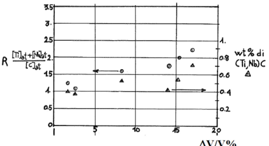
In the first generation double stabilized steels a high percentage in primary precipitation (the one occurring during annealing treatment) had been noticed. As a consequence the “in-service” precipitation resulted reduced, sometimes absent. In the first generation double stabilized steels the annealing temperature used, 1125°C, didn’t result sufficient to obtain a good solubilization of “free” Ti and Nb also because of the high stabilization ratio (3,18 for the 316DS and 2,04 for the 15-15DS). The precipitation of carbides doesn’t only act on the creep resistance of the material; it also has positive effects on the stability under irradiation. In figure 1 a graphical investigation of the first 90’s about the dependence of swelling attitude on the primary precipitation and on the stabilization ratio is reported.
Fig. 1. Relation between stabilization ratio, weight percentage of primary precipitation and swelling attitude for a 15Cr-15Ni austenitic matrix irradiated at 450°C with an irradiation
Regarding the previous Double Stabilization generation behaviour, the researchers have obtained a lower primary precipitation by modifications of chemical composition which lead to stabilization ratios of 1.38 for DS3 and 0.55 for the DS4 steel. With low stabilization ratios and a solution treatment at 1100°C it's possible to have a low primary precipitation, that means sufficient "free" contents of Carbon, Ti and Nb in solid solution in order to allow a secondary (in service) beneficial precipitation. A 2nd generation has then been realized based on 15 Cr-15 Ni and 15 Cr-25 Ni matrix. The whole tensile and creep program was achieved with test temperatures up to 850°C.
Fig. 2. Position of the Double-stabilized Steels inside the Shaffler’s diagram
Figure 2 shows the position of the second generation steels inside the Shaffler diagram .
The second generation of DS steels was based on a 15Cr–15Ni matrix, with a complete revision of the chemical composition and on a new matrix 15Cr–25Ni ( DS3 15-15 Ti+Nb, DS4 15-25 Ti+Nb ) [Ref.1]. Two kinds of products were realized in the form of rods (external diameter 8 mm) and cladding pipes (ext. diam. 6,55 mm, internal 5,65). The rods and the pipes were cold-worked with a final section reduction ratio of 20%. The annealing temperature before final cold-working was 1100°C ( 5 minutes in Argon atmosphere ), followed by air cooling.
These 2nd generation steels are characterized by a medium grain size, measured by the linear intersection method, in the order of 32-45 micron (N° 7 and 6 ASTM). The optical microscopy showed a low primary precipitation, particularly in the steels with high Nichel content characterized by intergranular dispersion of mixed carbo-nitrides (Ti + Nb). The Vickers hardness values for both the steels varied between 260 (DS4) and 270 kg/mm^2 (DS3) with an applied load of 98 N.
2. CREEP BEHAVIOUR
A single lever MAYES jigs with autolevelling arm device has been used to perform creep tests. A three zones P.I.D. controlled furnace and the utilization of S type thermocouples allow the temperature gradient to be maintained at ± 1°C along the gauge length. Test temperatures for DS4 steel range from 550 to 850°C, while DS3 has been tested just up to 750°C. Extensometric device clamped to the specimen's ridges was linked to a pair of capacitance type transducers. The whole system measures elongation of the specimen with an accuracy of 0.2 µm. A completely automatized data logging of strain and elapsed time provide elaboration and drawing of creep curves. The creep tests were performed in constant load conditions.
T (°C) σσσσ(MPa) (1/h) t0.2(h) tR(h) 550 430 0.258 3291 460 0.468 1323 3265 17.23 60.01 490 0.275 241 1773 11.92 56.84 580 2953.1 n.m. 0.5 13.59 62.68 650 300 4.796 67.4 320 31.676 32.4 340 69.051 20.7 213 23.65 66.82 350 72.149 17.6 137 16.38 65.02 750 110 11.735 119.6 1255 62.52 86.48 140 12.164 101 492 32.32 84.2 170 21.593 66 198 37.84 83.02 200 29.539 31.2 119.5 27.64 80.13
Table 1. Creep properties of DS3 steel [Ref.1]
T (°C) σσσσ(MPa) (1/h) t0.2(h) tR(h) 550 400 0.394 1560 2628 1.56 4.25 430 0.568 1111 2140 1.67 3.74 460 1.753 620 1424 2.25 5.97 490 3.582 125 765 7.79 10.88 520 6.041 4 575 6.07 18.35 550 42.436 0.52 238 9.47 26 580 331.73 0.26 93.4 14.89 44.66 650 250 0.386 2096 10507 16.58 68.76 300 0.949 18.5 5637 19.34 57.54 320 2.691 14 2570 12.96 63.2 340 10.393 3 1067 12.97 54.94 350 131.188 1.71 126.2 10.68 41.61 390 572.69 2.02 26 12.52 44.49 750 90 1.212 1633 110 1.356 955 3358 36.58 85.11 140 10.312 106 802 28.88 83.34
170 16.206 34 384 32.29 79.32 200 64.209 12.8 119 29.19 77.15 240 356.75 3.5 23.6 19.01 70.75 850 10 0.252 4962 40 16.601 112 544 52.69 91.07 50 17.856 108 354 49.89 90.59 60 31.42 50.3 167 63.62 92.49 70 173.07 8.7 46.2 37.35 89.91 90 285.87 3.4 24.1 44.89 93.08 110 471.76 6.9 26.1 37.84 86.41
Table 2. Creep properties of DS4 steel [Ref.1]
In table 1 and 2, data referring to creep properties of DS3 and DS4 steel respectively, are reported, the meaning of each column being explained as follows:
is quantified in units
t0,2 is the time to attain 0.2% of creep elongation
tR is the rupture-time is elongation at failure
means Reduction of Area at failure
Fig. 3. Comparison between DS3 and DS4 concerning time to reach a deformation of 0.2%
MPa
Fig. 4. Comparison between DS3 and DS4 concerning time to rupture
In graphs 3 and 4 the times to 0,2% deformation and to rupture are reported. The general trend for these characteristics is very similar to the minimum creep-rate one: DS3 steel seems to behave better than DS4 at stresses lower than about 500 MPa and low temperature (550°C), while for higher temperatures there’s a transition point; this better behaviour appears for stresses higher than 340/350 MPa at 650 and about 140 MPa at 750°C. Figure 5 shows a comparison in creep time to rupture between DS3 and other 15Cr-15Ni steels. The double stabilized steel (filled dots) definitely performs a better behavior in comparable temperature conditions.
Fig. 5. Comparison in time to rupture between DS3 (filled dots) and other 15Cr-15Ni steels [Ref. 10]
h MPa
3. BEHAVIOUR UNDER IRRADIATION; THE RESULTS OF THE
EXPERIENCE “SUPERNOVA”
The following graph (figure 6) shows the very promising results obtained in the Supernova experiment in Phénix reactor with an irradiation damage of 89 dpa. One challenge is to find a compromise between low swelling and good ductility after irradiation. The comparison of advanced austenitic steels shows the beneficial effect of cold working, increasing Ni percentage, stabilization by Ti and Nb addition performed on the second generation stainless steels. The comparison between micrographies shows how the Limited swelling of advanced austenitic steels is consistent with low amount of cavities (figure 7).
Fig. 6. Limited swelling of the advanced austenitic steels [Ref. 11]
Fig. 7. Low amount of cavities in the advanced austenitic stainless steel (b) if compared to the non-optimized 15-15 Ti (a) [Ref. 11]
4. PRELIMINARY RESULTS OF THE CORROSION TESTS
PERFORMED AT ENEA BRASIMONE
The preliminary results presented in the following pages refer to corrosion tests performed in ENEA Brasimone laboratories between june and august 2013. The boundary conditions are listed below:
• Specimen considered: DS3 (15Cr-15Ni) DS4 (15Cr-25Ni) and DS5 (15Cr-25Ni)
• Stagnant lead environment: the specimen is plunged for half of its length in an Al2O3 glass filled with molten lead;
• Oxiding atmosphere: oxygen content approximately between 10^-6 and 5.10^-4 wt% • Temperature of the bath kept at 550°C
• Duration of the test: 900h (DS4)-1000h (DS3,DS5)
The micrographies show that the sample has undergone oxidizing processes both in the plunged side and in the not submerged one; the thickness of the oxide layer is narrower in the not plunged side (see fig. 8).
Fig.8. Difference in oxide width between the plunged and the not plunged side of the sample in DS5 steel
The oxide layer thickness ranges around an average width of 8-10 µm in the plunged area for the steels with higher content in Nb ( DS3 and DS5). Concerning the steel with lower content in Nb (the DS4), instead, the oxide layer thickness ranges around an average width of 15-20 µm (fig. 9). Concerning the expected width of the oxide layer for an austenitic steel, our results don’t seem to be in agreement with the ones obtained in other experimental campaigns in LBE (see fig 10). In two of the DS steels, the DS3 and the DS5, the ones with the higher content in Nb, the oxide width appears a few microns larger than the 5-6 microns expected after 1000 h of exposure. In the DS4 this value results even doubled.
Fig.9. Comparison between the width of the oxide layer formed in the DS4 (15Cr-25Ni, low Nb) (a) and in the DS5 (15Cr-25Ni, high Nb) (b)
Fig.10. Thicknesses of oxide [Ref.14] as a function of corrosion duration for austenitic steels in LBE for 500°C temperature range
In the plunged side, where lead comes in contact with the austenitic matrix, a transition zone, with probable migration of Cr and Ni, has been detected in each one of the 3 steels (see fig. 11). This ferritic zone between the external oxide layer and the inner austenitic substrate isn’t detectable in the not plunged side of the specimen. The average dimension of the ferritic zone of transition is 5-7 µm. Concerning DS3 and DS5, the dimension of the whole area affected by oxidation processes, resulting by the sum of the oxide layer and the ferritic zone, presents an average value of about 10 µm but it reaches a maximum width of about 30 µm in the lower part of the crucible (see fig. 12).
Fig. 11. Transition zone (faded grey) only detectable in the plunged side of the sample (a) and schematic drawing of the formation of the ferritic zone of transition in an austenitic steel (b)
Fig.12. Maximum width of oxide layer and transition zone together
The observations reported in this paper must be considered just as a first step towards the characterization in lead of these steels; more precise informations will come out in the future as soon as new material, deriving from the procurement described in this report, will be available.
5. Scope of the Supply
The aim of the present Supply is
• the implementation and reporting concerning the manufacturing process for the production of DS4 stainless steel plates;
• the delivery of ingots and the production of DS4 SS plates, (about 50 kg) • the preliminary characterization by tensile tests
• the shipment of the plates by the C.R. ENEA Brasimone, Italy.
a
6. Technical Specification – DS4 Steel
Chemical Composition
Weight Percent
C desiderata 0,05 specifica 0,04<C<0,06
Cr desiderata 15 specifica 14<Cr<16
Ni desiderata 25 specifica 24,5<Ni<25,5
Mo desiderata 1,5 specifica 1,2<Mo<1,8
Mn desiderata 1,5 specifica 1,2<Mn<1,8
Si desiderata 0,9 specifica 0,8<Si<1
Ti desiderata 0,15 specifica 0,1<Ti<0,3
Nb desiderata 0,15 specifica 0,1<Nb<0,3 V specifica V<300 ppm N desiderata 150 ppm specifica N<200 ppm P desiderata 400 ppm specifica 350ppm<P<450ppm B desiderata 50 ppm specifica B<60 ppm Al desiderata 150 ppm specifica Al < 200ppm S desiderata 70 ppm specifica S<150ppm Cu specifica Cu<0,1 ppm Co specifica Co<0,1 ppm Ca specifica Ca<0,03 ppm Ta specifica Ta<0,03 ppm Zr specifica Zr<0,03 ppm W specifica W<0,03 ppm
Production
− Melting and re-melting in void (VIM process) − Production of the lab ingots
− Homogenization Annealing 1200°C per 2 ore − Chemical and metallographic analysis.
− Production of the plates by hot rolling; final thickness suitable to reach 15 mm thickness after CW o Max heating temperature: 1150°C
o Min rolling temperature: 800°C
− Ultrasound and RX check to discard the defective parts
− Final Annealing before CW: 1100°C for 5 minutes, subsequent cooling in Argon atmosphere − Cold Working; section reduction ratio 20% with final thickness 15 mm
− Chemical and metallographic analysis.
Characterization Tests
− 10 tensile tests at room temperature according to the ASTM E8 rules (constant elongation rate); − 10 tensile tests at 550°C according to the ASTM E21 rules (constant elongation rate);
Documentation follow up
The supply will be completed by a documentation set follow up. The following documents will be delivered:
• Report on the manufacturing of DS4 SS plates (Annex 1);
• Composition check for each ingots and plates produced (Annex 2);
7. BIBLIOGRAPHY
[1] G.FILACCHIONI, A.CALZA BINI and L.PILLONI: Development of a New Family of Austenitic Alloys: The Double Stabilized Stainless Steels. Design Criteria and Metallurgical Properties - Proceedings of Int Conf. on Evolution of Advanced Materials, Milan (1989), 89-94
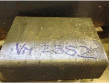
ANNEX – 1 - Fabbricazione lingotto DS4
Il lingotto DS4 (fig.1) è stato realizzato all’interno del laboratorio “Tecnologie Fusorie & Chimica Metallurgica”, mediante la tecnologia fusoria in vuoto VIM (Vacuum Induction Melting), che è il processo di fusione più versatile per la produzione di quasi tutte le leghe speciali base Fe, Ni e Co.
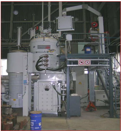
L’impianto VIM del CSM (ALD-Vacuum Tecnologies) (fig. 2 ) impiegato per la produzione dei lingotti, possiede le seguenti caratteristiche tecniche:
• Intervalli di fusione: 1300 – 1600 °C;
• Atmosfera: Vuoto/gas inerte;
• Pressione di lavoro: da 5 x 10⁻⁵ mbar a 300 mbar;
• Range di misura temperature: da 750 a 1800°C (tramite termocoppie e pirometri ottici);
• Colaggio: Lingottiera/Guscio ceramico;
• Volume di fusione/colaggio: da 1 a 11 dm3;
Fig. 1 – Lingotto DS4
Il processo di fusione della carica avviene tramite una bobina di rame, raffreddata ad acqua, attraverso la quale passa una corrente alternata che avvolge il crogiolo di refrattario generando così delle correnti parassite nel materiale di carica che si scalda per effetto joule.
L’agitazione (‘stirring magnetico’) che il processo genera nel bagno garantisce sia la omogeneizzazione e il controllo più accurato della chimica e della temperatura del fuso, sia il trasporto di materia necessario per lo svolgimento delle reazioni chimico-fisiche richieste, come per esempio, il degasaggio.
Tale processo garantisce inoltre un’esatta composizione e riproducibilità del prodotto. Il ciclo di fusorio in un forno VIM è strutturato in diversi passaggi: carica, fusione, affinazione, analisi chimica e correzione della composizione, colaggio.
Il materiale di carica è comprensivo degli elementi leganti, eccetto i costituenti reattivi, che vengono introdotti successivamente mediante un sistema di carica posto
sulla sommità del forno. Durante la fusione e l’ affinazione avvengono reazioni quali il degasaggio e la disossidazione.
Alla fine del periodo di affinazione vengono introdotti, se necessari, gli elementi reattivi quali Si e Mn.
Fig. 2 – Impianto VIM (ALD-Vacuum Tecnologies) presso il CSM
Dopo un tempo richiesto per il mescolamento ottimale del bagno si procede ad un’analisi chimica ed ad eventuali aggiunte di alliganti nel caso di carenze nella composizione. Alla fine il fuso viene colato in lingottiera.
In questo caso per i materiali di carica sono state utilizzate materie prime con purezza non inferiore al 99.9%.
Sono stati prodotti n°1 lingotto, di dimensioni 200x100 mm e altezza 400mm per un totale di circa 40kg di materiale.
Il ciclo fusorio seguito è mostrato inoltre in fig. 3. Il grafico riporta l’andamento dei valori di vuoto, di potenza e di temperatura del forno ad induzione in funzione delle diverse fasi del processo.
Fig. 3 - Differenti fasi del ciclo fusorio
I risultati ottenuti in termini di composizione chimica sono riportati nella tabella di seguito, in cui si evince il perfetto raggiungimento dei target composizionali richiesti.
Specifica richiesta

![Table 1. Creep properties of DS3 steel [Ref.1]](https://thumb-eu.123doks.com/thumbv2/123dokorg/5629058.68875/5.892.216.680.397.695/table-creep-properties-ds-steel-ref.webp)


![Fig. 6. Limited swelling of the advanced austenitic steels [Ref. 11]](https://thumb-eu.123doks.com/thumbv2/123dokorg/5629058.68875/8.892.122.764.415.1043/fig-limited-swelling-advanced-austenitic-steels-ref.webp)