Carlo Parisi
NUCLEAR SAFETY
OF
RBMK REACTORS
Scuola di Dottorato in Ingegneria “Leonardo da Vinci”
Corso di Dottorato di Ricerca in
SICUREZZA NUCLEARE ED INDUSTRIALE
Tesi di Dottorato di Ricerca
Autore:
CARLO PARISI
Firma___________________
Relatori:
Prof. Francesco D’Auria (UNIPI) Firma_____________
Dr. Gianni Petrangeli Firma_____________
Prof. Eugenius Uspuras (LEI) Firma_____________
Dr. Sergei L. Soloviev (NIKIET) Firma_____________
NUCLEAR SAFETY OF
RBMK REACTORS
UNIVERSITÀ DI PISA
Scuola di Dottorato in Ingegneria “Leonardo da Vinci”
Corso di Dottorato di Ricerca in
SICUREZZA NUCLEARE ED INDUSTRIALE
ACKNOWLEDGMENTS
This PhD thesis was developed at the San Piero a Grado Nuclear Research Group of the University of Pisa. So, my first thank is due to the leader of this Group and thesis supervisor, prof. F. D’Auria. He gave me the opportunity to perform this job in a fruitful and stimulating environment, and he always supported and encouraged the research activities. I appreciated also his example in looking at the RBMK technology without any prejudice.
I would like to give also special thanks to the other PhD thesis supervisors, Dr. G. Petrangeli, prof. E. Uspuras and Dr. S. L. Soloviev, for their collaboration, suggestions and for the trust they showed in my activities.
Dr. V. Malofeev from Kurchatov Institute and Prof. K. N. Ivanov from the Pennsylvania State Univeristy helped me a lot with their advises on the neutron transport calculations. I am very grateful to them.
A special mention is due to the NIKIET staff, led by Dr. B. Gabaraev, for their kind hospitality and assistance provided during my stays in Russia.
I would like to thank also Dr. B. Ivanov, from Westinghouse Electric and Dr. E. Vanagas, from the Lithuanian Safety Authority for the useful conversations I had with them on the RBMK HELIOS models.
This work would not be possible if I did not have the opportunity to work in the serious and at the same time friendly environment of the San Piero a Grado Nuclear Research Group. For this reason I am grateful to all my present colleagues and to the whole original team of persons that from 2004 to 2006 contributed with dedicated work to the unquestionable success of the TACIS Project R2.03/97, from which this PhD work originated.
My final thanks and dedication of this work should go to my parents, and especially to my father. During all these years he staunchly supported and encouraged me to perform and finalize the PhD activities, reminding, when difficulties seemed discouraging, that “..non est ad astra mollis e terra via”.
SOMMARIO
La presente Tesi di Dottorato esamina il livello di sicurezza dei reattori di potenza raffreddati ad acqua bollente e moderati a grafite (reattori RBMK), mediante l’uso di codici di calcolo best-estimate termoidraulici e neutronici accoppiati. La disponibilità di tali sofisticati strumenti ha reso possibili, infatti, analisi dettagliate e realistiche anche per questo tipo di impianti nucleari, notoriamente complessi e comunemente denominati “reattori di tipo Chernobyl” (in riferimento al gravissimo incidente occorso ad uno di questi impianti nel 1986). Parte delle attività della presente Tesi di Dottorato, si sono svolte nell’ambito del Progetto TACIS R2.03/97 “Software development for the RBMK and WWER reactors”, coordinato dal Gruppo di Ricerca Nucleare San Piero a Grado dell’Università di Pisa in collaborazione con i progettisti e gli esercenti russi di tali impianti (NIKIET, Kurchatov Institute, RosEnergoAtom, oggi EnergoAtom Concern OJSC).
Le attività di ricerca hanno contemplato lo sviluppo di una complessa nodalizzazione termoidraulica dell’unità 3 dell’impianto nucleare di Smolensk, la sua validazione ed il suo successivo accoppiamento con un modello di cinetica neutronica tridimensionale. Il codice utilizzato è il RELAP5-3D. I calcoli di neutronica hanno richiesto, preliminarmente, lo sviluppo di librerie di sezioni d’urto macroscopiche. Tale attività, è stata svolta in collaborazione con la Pennsylvania State University, ed ha comportato l’utilizzo del codice di trasporto deterministico HELIOS.
Dopo la validazione dei modelli sviluppatii, si sono eseguite analisi di transitori a piena potenza, focalizzandosi su quelli particolarmente critici per la sicurezza (per esempio, la rottura di un collettore dei canali di potenza o del sistema di raffreddamento delle barre di controllo). Una speciale enfasi è stata data, anche mediante l’uso del codice Montecarlo MCNP5, allo studio del transitorio contemplante il bloccaggio di un canale di potenza.
L’ultima parte delle attività di dottorato si sono concentrate sull’analisi di un transitorio a bassa potenza, ricostruendo uno scenario incidentale estremo come quello occorso a Chernobyl. Le sezioni d’urto di cella per lo Xeno sono state calcolate con il codice al trasporto deterministico DRAGON.
In conclusione, le analisi avanzate effettuate nell’ambito di questa Tesi di Dottorato, hanno confermato il migliorato grado di sicurezza di tali impianti, ottenuto grazie alle importanti modifiche effettuate a seguito dell’incidente di Chernobyl.
ABSTRACT
This PhD thesis is evaluating the safety level of the graphite-moderated boiling water cooled nuclear power reactors (RBMK reactors) by the use of best estimate three dimensional neutron kinetics coupled thermal-hydraulics codes. The availability of such sophisticated tools has allowed detailed and realistic analyses of these kind of reactors, also known as “Chernobyl-type” reactors. Chernobyl is the name of a RBMK reactor where, in 1986, a severe accident occurred, leading to the destruction of the plant and to a major release of radioactivity into the environment. Parts of the activities of this PhD thesis were developed in the framework of the European Union funded TACIS Project R2.03/97 “Software development for the RBMK and WWER reactors”. This project was awarded to the “Gruppo di Ricerca Nucleare San Piero a Grado” of the University of Pisa and managed by it in collaboration with the RBMK designers (NIKIET, Kurchatov Insititute) and the licensee (RosEnergoAtom, now EnergoAtom Concern OJSC). The research activities dealt with the development and the validation of a sophisticated thermal-hydraulic nodalization of the Smolensk-3 Nuclear Power Plant. This thermal-hydraulic model was then coupled with a three dimensional neutron kinetics model of the core. The code used was RELAP5-3D system code. Suitable RBMK cross sections libraries were developed in collaboration with the Pennsylvania State University, using the deterministic lattice physics code HELIOS.
After the validation of the developed models, the most relevant transients for the plant safety at full power were calculated, e.g. the group distribution header rupture, the break of the control and protection system cooling circuit. A special emphasis was put in the simulation of the single fuel channel transient, using also the Monte Carlo code MCNP5.
The last part of the PhD activities concerned the analysis of a low power transient. In particular, the Chernobyl extreme scenario was reconstructed. Xenon fuel cell cross sections were calculated using the deterministic transport code DRAGON. Finally, all the analyses performed in the framework of this PhD confirmed the upgraded level of nuclear safety of the RBMK reactors, obtained also as a consequence of the relevant hardware modifications implemented in the aftermath of the Chernobyl accident.
CONTENTS
ACKNOWLEDGMENTS... I SOMMARIO... III ABSTRACT ... IV CONTENTS. ... V NOMENCLATURE ... IX LIST OF SYMBOLS ... XIII LIST OF FIGURES ...XV LIST OF TABLES...XXII1.INTRODUCTION ... 1
1.1.State of the Art on the RBMK Safety Analyses... 1
1.2. Scope 2 1.3. Objectives... 3
1.4. Structure... 3
2. THE DESCRIPTION OF THE RBMK ... 5
2.1. The Primary System ... 8
2.1.1. The pressure boundary ... 8
2.1.2. The core ... 15
2.1.2.1. The fuel ... 15
2.1.2.2. The Absorbers and the Power Control System... 18
2.1.2.3. The scram signals ... 22
2.1.2.4. The fuel cell neutronic characteristics ... 23
2.1.2.5. Reactivity Control ... 26
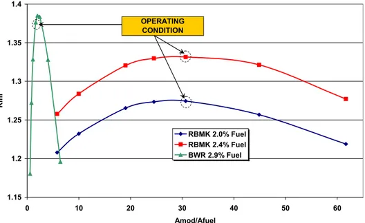
2.1.2.5.1. Fuel Cell Overmoderation ... 26
2.1.2.5.2. The Operating Reactivity Margin ... 27
2.1.2.5.3. The Reactivity Coefficients ... 28
2.1.3. The Balance of Plant ... 29
2.2. The Confinement System... 32
2.2.1. The Reactor Cavity... 34
2.2.2. The Accident Localization System ... 35
2.2.4. The fuel loading machine hall ... 38
2.3. The Engineered Safety Features and the Emergency System……….. ... 38
2.4. The reference plant and the reference conditions: Smolensk-3, 16 October 1996 ... 42
2.4.1. Reference fuel load map... 42
3. THE BACKGROUND FOR RBMK ACCIDENT ANALYSIS ... ..47
3.1.The technological status for RBMK safety... 47
3.1.1. The background ... 47
3.1.2. The relevant aspects... 48
3.2. The safety needs... 53
3.2.1. The RBMK acceptance criteria... 55
3.2.1.1. Fuel clad integrity ... 56
3.2.1.2. Fuel channel integrity... 56
3.2.1.3. MCC integrity ... 58
3.2.1.4. RC integrity ... 58
3.2.1.5. ALS integrity ... 59
3.2.1.6. The permissible radiation doses... 61
3.2.2. Recent requirements by RosTechnadzor pertaining to BDBA analysis including SA... 62
3.3.Identification and characterization of selected RBMK accident scenarios and phenomena ... 65
3.3.1.Thermal-hydraulics of PS ... 65
3.3.2. Three-dimensional neutron kinetics... 69
4.THE TOOLS, THE METHODOLOGIES AND THE QUALIFICATION OF 3D NK COUPLED TH CODES ANALYSES ... 71
4.1. Neutron Transport codes... 71
4.1.1. The Monte Carlo code MCNP5 ... 71
4.1.1.1. General features ... 71
4.1.1.2. Monte Carlo Method vs. Deterministic Method ... 72
4.1.1.3. The Monte Carlo Method... 72
4.1.1.4. Nuclear Data and Reactions ... 73
4.1.1.5. Tallies and Output ... 74
4.1.1.6. Estimation of Monte Carlo Errors ... 74
4.1.2.The deterministic transport codes ... 75
4.1.2.1. The lattice physics code DRAGON ... 76
4.1.2.2. The lattice physics code HELIOS... 77
4.2.The RELAP5-3D system code... 80
4.2.1. Introduction ... 80
4.2.3. The Thermal-hydraulic part: the RELAP5-3D code ... 82
4.2.4. The three dimensional neutron kinetics routine: the NESTLE code ... 83
4.2.4.1. The Steady-State and the Transient Problem... 83
4.2.4.2. The Cross Section and the feedbacks... 86
4.2.4.3. The GEN neutron cross section model ... 88
4.3.The Cross Section Processing methodology ... 91
4.3.1. Introduction ... 91
4.3.2. The State of the Art methodologies... 91
4.3.3. The Methodology for the RBMK calculations ... 96
4.4. The coupling methodology... 97
4.5. The procedure for code application including the nodalization ………... .98
4.5.1.Introduction ... 98
4.5.2. The HELIOS code model... 99
4.5.2.1. Core geometry ... 99
4.5.2.2. The Cross-section library ... 106
4.5.3.The RELAP5-3D TH nodalization ... 111
4.5.4. The NESTLE 3D NK nodalization and the coupling ... 123
4.5.4.1. 3D NK-TH Coupling Scheme ... 124
4.5.4.2. Some considerations on the axial meshing scheme ... 129
4.5.5.The MCNP5 code model ... 130
4.5.5.1. Reference Geometry Material... 130
4.5.5.2. Reference Material data ... 131
4.5.5.3. MCNP5 Reference Model Geometry ... 132
4.5.5.4. MCNP5 Cross Section Libraries... 133
4.5.5.5. Boundary Conditions ... 133
4.5.6. The DRAGON code model ... 133
4.5.6.1. Cross Section Libraries ... 134
4.5.6.2. Boundary Conditions ... 134
4.5.6.3. Calculation modules... 134
4.6.The Qualification... 135
4.6.1. Codes qualification ... 135
4.6.1.1. The RELAP5-3D validation for RBMK analyses ... 135
4.6.1.2. The HELIOS code validation for RBMK analyses... 136
4.6.1.3. The DRAGON code validation for RBMK analyses ... 136
4.6.1.4. The MCNP validation for RBMK analyses... 136
4.6.2.Model and Nodalization qualification ... 137
4.6.2.1. RELAP5-3D TH nodalization qualification... 137
4.6.2.2. RELAP5-3D 3D NK nodalization qualification ... 142
4.6.2.3. HELIOS model qualification ... 146
4.6.2.4. The MCNP5 model qualification... 147
4.6.2.4.1. Sensitivity analyses... 148
4.6.2.4.2. Geometry Variation ... 148
4.6.2.4.3. Cross Section Libraries Variation... 148
4.6.2.4.5. Calculation Parameters Variation ... 148
4.6.2.4.6. Results of Sensitivity Analyses ... 150
4.6.2.5.The DRAGON model qualification ... 151
5. THE APPLICATION TO REALISTIC TRANSIENTS ANALYSES…………. ...…153
5.1.Hot Full Power Analyses... 153
5.1.1. Reactivity Initiated Accidents ... 153
5.1.1.1.CR Withdrawal ... 154
5.1.1.2. CR Group Withdrawal... 161
5.1.2.Decrease of coolant flow events... 169
5.1.2.1. GDH blockage ... 169
5.1.2.2. Fuel Channel Blockage: the System Code Analysis... 175
5.1.2.3. The Fuel Channel Blockage: the FC criticality calculations .. 179
5.1.2.3.1. Introduction ... 179
5.1.2.3.2. Single Fuel Channel - 2.0% Fuel ... 179
5.1.2.3.3. Single FC – 2.4% Fuel ... 182
5.1.2.3.4. Lattice Cell Analysis ... 185
5.1.2.3.5. Conclusions... 196
5.1.3.LOCA events ... 169
5.1.3.1.CPS-LOCA ... 197
5.1.3.2. GDH LOCA (rupture after the GDH check valve)... 200
5.2.Conclusion ... 208
6. THE EXTREME CASE ... 209
6.1. Introduction... 209
6.2. The Chernobyl event ... 209
6.3. Literature review ... 214
6.4. Low Power analyses – the model upgrade ... 214
6.4.1. Xenon modelling ... 215
6.4.2. Power Control modelling ... 215
6.5. The Power-reduction transient... 216
6.6. The “Chernobyl-like” event ... 220
6.6.1. Reference Transient ... 221
6.6.1.1. Positive Reactivity Perturbation ... 226
6.6.1.2. No Scram actuation ... 227
6.6.2.Conclusions ... 227
NOMENCLATURE
0D Zero-dimensional 1D One-dimensional 2D Two-dimensional 3D Three-dimensional AA Additional AbsorberACC Accumulator (part of the ECCS, also identified as hydro-accumulator) ACRR Annular Core Research Reactor (Sandia National Lab)
ADF Assembly Discontinuity Factor
AECL Atomic Energy of Canada Limited
AHTLM Adaptive High-order Table Look-up Method
ALS Accident Localization System
ALT Accident Localization Tower
ANM Analytical Nodal Method
ANS American Nuclear Society
ANS Advanced Neutron Source (Oak Ridge National Lab)
AOO Anticipated Operational Occurrences
ATR Advanced Test Reactor
ATWS Anticipated transient without scram AZ-1, AZ-3 to
AZ-6 RBMK Emergency Protection Signals (Scram or Power reduction)
AZM (Signal of) Emergency Protection by Power
BAZ RBMK scram key (Fast functioned emergency protection)
BDBA Beyond Design Basis Accident
BE Best Estimate
BIC Boundary and Initial Conditions
BPLU Border Profile Lower Upper (Matrix Solver) BRU-K, -D, -TK Safety Valves on Steam Lines
BWR Boiling Water Reactor
CHF Critical Heat Flux
ChNPP Chernobyl Nuclear Power Plant
CMFD Coarse Mesh Finite Difference
CAMP Code Assessment and Maintenance Program
CANDU Canadian deuterium uranium (reactor) CCPM; Current-Coupling Collision Probability Method
CPM Collision Probability Method
CPS Control and Protection System
CPU Central Processing Unit
CR Control Rod
CRCC Control Rod Cooling Circuit
CTV Control Throttling Valve
DBA Design basis accident
DC Down-Comer
DF Discontinuity Factor
DREG Diagnostic Parameter Recording Program
DS Drum Separator, see also SD or Steam Drum
EC The European Commission
ECCS Emergency Core Cooling System
ENDL Evaluated Nuclear Data Library
ENDF Evaluated Nuclear Data File -
ESF Engineered Safety Features
FASS Fast Acting Scram System
FDM Finite Difference Method
FLOP Floating Operation
GDH Group Distribution Header
GRNSPG The San Piero a Grado Nuclear Research Group of the University of Pisa, Italy
DBA Design Basis Accident
DIMNP Department of Mechanical, Nuclear and Production Engineering of the University of Pisa, Italy
DS Drum separator
ECCS Emergency Core Cooling System
EPS Emergency Protection Signal
EREC Electrogorsk Research and Engineering Center
ET Equivalent Channel
FASS Fast Acting Scram System
FC Fuel Channel
FDM Finite Difference Method
FLOP Floating Point Operation
FP Fission Product
FSP Fixed Source Problem
GAN Gosatomnadzor, the former Russian Nuclear Safety Authority, now Rostechnadzor KI The Russian Research Center “Kurchatov Institute” or see RRC KI
HFBR High Flux Beam Reactor
HFIR High Flux Isotope Reactor
IAEA International Atomic Energy Agency
ICAP International Code Assessment and Applications Programme
ICV Isolated control valve
IGR Impulse Graphite Reactor
INL Idaho National Laboratory
LAC Local Automatic Control
LANL Los Alamos National Laboratory
LAP Local Automatic Protection
LAR Local Power Control
LEI Lithuanian Energy Institute
LOCA Loss of coolant accident
LOFT Loss of Fluid Test Reactor
LNPP Leningrad Nuclear Power Plant
LTC Leak-Tight Compartment
LWL Lower Water Line
MCC Main circulation circuit
MCP Main circulation pump
MCR Manual Control Rod
MFCC Multipass Forced Circulation Circuit
MPTR Multiple Pressure Tube Rupture
MSV Main Safety Valve
NEM Nodal Expansion Method
NIKIET “N. A. Dollenzhal” Institute for Power Engineering (RBMK designer)
NK Neutron Kinetics
NPR New Production Reactor
NRC Nuclear Regulatory Commission (U.S.A.)
NRU National Research Universal Reactor (Chalk River Lab)
NPP Nuclear Power Plant
ORM Operating Reactivity Margin
ORNL Oak Ridge National Laboratory
PDDMS Power Density Distribution Monitoring System PDMS-A Power Density Sensors of the Axial Monitoring
PH Pressure Header
PHWR Pressurized heavy water reactor
PSA Probabilistic Safety Analysis
PSP Pressure Suppression Pool
PSU The Pennsylvania State University
PT Pressure Tube
PWR Pressurized Water Reactor
RBMK Reactor Bolsoi Mochnosti Kipyashiy (Large Power Boiling Reactor)
RC Reactor Cavity
RCPS see MCR
RCSRV Reactor Cavity Steam Relief Valve
RCVS Reactor Cavity Venting System
RDFMG The Reactor Dynamics and Fuel Management Group
RIA Reactivity Initiated Accident
RRCC Radial Reflector Cooling Channels
RRC KI The Russian Research Center “Kurchatov Institute”
SA Severe Accident
SCS Sprinkler Cooling System
SCV Stop-control valve
SD Steam Drum
SDC Steam Corridor Distribution
SHR Shortened Control Rod
SL Steam Line
SOR Successive Over Relaxation
SPTR Single Pressure Tube Rupture
SR Safety Control Rod (components of FASS)
SRV Steam Relief Valve
SS Steady State
SV Stop Valve
TACIS Technical Aid to the Commonwealth of the Independent States TH Thermal-Hydraulic
TPEN Triangle-based Polynomial Expansion Nodal Method
URC Under Reactor Compartments
UNIPI The University of Pisa
VATESI Lithuanian Nuclear Power Safety Inspectorate
VVER see WWER
XSEC Cross-section (for 3D Neutron Kinetics calculations)
LIST OF SYMBOLS
Greek Symbols
aφ Void Reactivity Coefficient (pcm/% void)
aw Power Reactivity Coefficient (pcm/MWth)
at Doppler Reactivity Coefficient (pcm/°C)
ac Graphite Temperature Reactivity Coefficient (pcm/°C)
acool Coolant Temperature Reactivity Coefficient (pcm/°C)
β Delayed Neutron Fraction
f Neutron flux (n/cm2*s)
ε Fast Fission Factor
εR Error in the neutron flux calculation
γ Gamma Particle
h Fission Neutron per Neutron Absorption into the Fuel n Number of Fission Neutrons
µ Cosine of the direction angle for neutrons
ρ Reactivity
ρw Material Density (Kg/m3)
ξ Average Logarithmic Energy Loss
si Stress Intensity (MPa)
sXe Microscopic Xenon Absorption Cross Section (*106 barn)
Σa Macroscopic Absorption Cross Section (cm-1)
Σf Macroscopic Fission Cross Section (cm-1)
Σsg‘g Macroscopic Group-to-Group Scattering Cross Section (cm-1) n Σf Macroscopic Neutron Generation Cross Section (neutron* cm-1) τth Fermi age (cm2)
zi Strain Rate Intensity
Roman Symbols
$ Reactivity (1$ = 1 β )
B Neutron Flux Distribution Buckling (cm-1) (12)C
(6) Graphite (Nuclear Grade)
D Diffusion Coefficient (cm)
f Thermal Utilization Factor
eV Electron Volt
k Multiplication factor (eigenvalue)
j Neutron current
ji Rupture Strain Power (W/Kg)
L Diffusion Length (cm)
Lgil Average i-directed leakage for group g in node l
M Migration Length (cm)
p Resonance Escape Probability Factor
Tw Pressure Tube Temperature (K)
LIST OF FIGURES
Fig. 1 – Overall view of the RBMK NPP system... 5
Fig. 2 – Smolensk-3 NPP view ... 6
Fig. 3 – RBMK Main Circulation Circuit (MCC) flow diagram ... 8
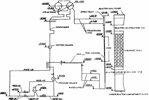
Fig. 4 – Key elevations in the MCC of the RBMK system (Smolensk 3)... 9
Fig. 5 – The MCP for RBMK NPP. ... 10
Fig. 6 – RBMK MCP (CVN-8) performance data (left: high temperature conditions, 265 ºC; right: low temperature conditions, 90 °C)... 11
Fig. 7 – Geometrical configuration of RBMK GDH ... 12
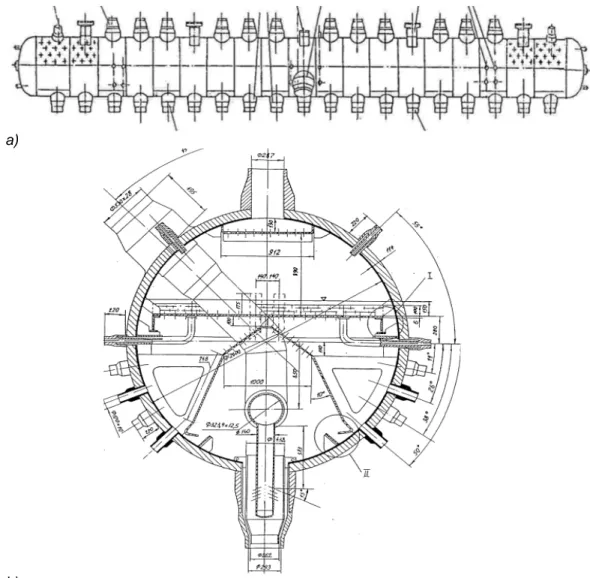
Fig. 8 – Geometrical configuration of RBMK SD: a) overall view; b) cross section13 Fig. 9 – Steam Drum – component specifications... 14
Fig. 10 – Layout of the two DS and related connection... 15
Fig. 11 – Geometrical configuration of RBMK core: a) detail of active region; b) overall view ... 16
Fig. 12 – Geometrical configuration of a) RBMK fuel bundle, b) fuel rod... 17
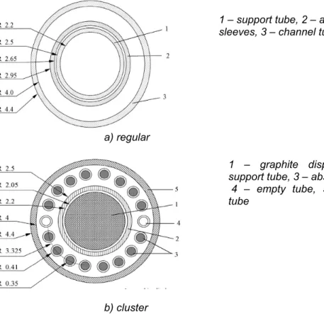
Fig. 13 – Geometrical and material configuration of RBMK FC ... 17
Fig. 14 – Geometrical and material configuration of regular and cluster type AAC of RBMK core... 18
Fig. 15 – Longitudinal view of RBMK CRs (Short, Safety and Manual types)... 20
Fig. 16 – Cross sectional view of RBMK regular CR... 21
Fig. 17 – Flow diagram of the CPS cooling system... 21
Fig. 18 – Fuel Cell basic model ... 24
Fig. 19 – Thermal neutron flux distribution ... 25
Fig. 20 – Fast neutron flux... 25
Fig. 21 – Neutron flux distribution... 26
Fig. 22 – kinf versus moderation ratio of Moderator area on Fuel area... 27
Fig. 23 – Flow diagram of the BOP system of the RBMK core ... 30
Fig. 24 – Flow diagram of SL from the SD region till the MSVs ... 31
Fig. 25 – Flow diagram of RBMK SL from the MSIV till the turbines... 31
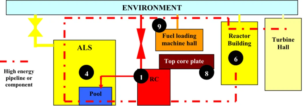
Fig. 26 – Sketch of the confinement system of the RBMK NPP with main sub-systems (numbers refer to components identified in Fig. 3.1, where applicable)... 32
Fig. 27 – Cross sectional view of the RBMK confinement system ... 33
Fig. 28 – Longitudinal view of the RC of a RBMK NPP... 34
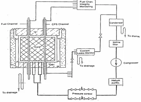
Fig. 29 – Gas removal system of the RC of a RBMK NPP... 35
Fig. 30 – Sketch of the Ignalina ALS ... 37
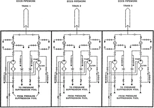
Fig. 31 – Main (or Short-term) ECCS subsystem, RBMK damaged core side delivery system ... 39
Fig. 32 – Long-term ECCS subsystem, RBMK damaged core side delivery system ... 40
Fig. 33 – Long-term ECCS subsystem, RBMK un-damaged core side delivery system... 41
Fig. 34 – The reference map of fuel load of the Unit-3 of Smolensk NPP (16.10.96) ... 42
Fig. 36 – Core Channels Flow Map (Kg/s) ... 46
Fig. 37 – Best estimate and conservative safety analysis: definitions of acceptance criteria and safety margins, [12]... 55
Fig. 38 – Pressure tube rupture temperature versus internal pressure... 57
Fig. 39 – Specific rupture strain power as a function of tube temperature... 57
Fig. 40 – A typical neutron history simulation by MNCP5 (from [24])... 73
Fig. 41 – HELIOS package... 77
Fig. 42 – Flow scheme of library generation. ... 79
Fig. 43 – Overview of the nested iterative solution strategy... 86
Fig. 44 – Cross Section dependence ... 92
Fig. 45 – Cross-section interdependence between fuel temperature and moderator temperature... 93
Fig. 46 – Cross-section calculation points for the polynomial fitting procedure ... 94
Fig. 47 – Areas of inaccurate cross-section calculation using the polynomial fitting procedure ... 94
Fig. 48 – The PSU transient cross-section representation... 95
Fig. 49 – RBMK Libraries Cross Section – Thermal absorption trend for composition 29 (see section 4.5.2) ... 96
Fig. 50 – RBMK Libraries Cross Section – Thermal fission trend for composition 29 (see section 4.5.2) ... 97
Fig. 51 – Codes and Models developed for 3D NK TH RBMK analyses ... 98
Fig. 52 – HELIOS modeling of RBMK FC cell ... 100
Fig. 53 – HELIOS modeling of RBMK MCR cell... 100
Fig. 54 – Core neutron kinetic mesh... 101
Fig. 55 – Two-dimensional channel type map (core left part) ... 104
Fig. 56 – Two-dimensional channel type map (core right part) ... 105
Fig. 57 – Interpolation Scheme for Cross Sections parameters... 107
Fig. 58 – Macroscopic cross-section table’s structure... 110
Fig. 59 – Sketch of the reference RELAP5-3D TH nodalization of Smolensk-3 (only left MCC showed) ... 112
Fig. 60 – Sketch of the simplified RELAP5-3D TH nodalization (Left and Right MCC)... 113
Fig. 61 – RELAP5-3D model of Smolensk 3 NPP: nodalization sketch of FW and SL systems... 114
Fig. 62 – RELAP5-3D model of Smolensk 3 NPP: nodalization sketch of down-comers up to the water lines. ... 115
Fig. 63 – RELAP5-3D model of Smolensk 3 NPP: nodalization sketch of core, FC exit lines and CPS cooling system... 115
Fig. 64 – Relap5 UNIPI model of Smolensk 3 NPP: nodalization sketch of ECCS. ... 117
Fig. 65 – RELAP5-3D Core neutron kinetic mesh... 124
Fig. 66 – TH / 3D NK & Lattice Codes meshes coupling... 125
Fig. 67 – Radial Arrangement of TH Channels for General Purpose Nodalization ... 126
Fig. 68 – Correlation map between TH channels, TH Zones and NK Nodes for General Purpose Nodalization ... 127
Fig. 69 – CR Numbers & Types – RELAP5-3D Numeration ... 128
Fig. 70 – Relative Axial Power: SS sensitivity, FD method calculations ... 129
Fig. 72 – Fuel Channel Cross-View... 130 Fig. 73 – Fuel Cell in XY plane (at Z=10) ... 132 Fig. 74 – Fuel Cell in YZ and XZ plane (at X=0 and Y=0) ... 132 Fig. 75 – DRAGON RBMK FC model... 133 Fig. 76 – DRAGON code: calculation scheme used for RBMK calculations... 134 Fig. 77 – RELAP5-3D Smolensk 3 NPP: nodalization qualification at steady state
level, comparison between adopted and reference (design) volume vs height curve of MCC. ... 138 Fig. 78 – RELAP5-3D Smolensk 3 NPP: nodalization qualification at steady state
level, comparison between steady state and reference (nominal conditions) pressure distribution along the MCC. ... 140 Fig. 79 – RELAP5-3D Smolensk 3 NPP: nodalization qualification at steady state
level, comparison between steady state and reference (nominal conditions) void fraction at SD inlet, right part, channels 1-24. ... 140 Fig. 80 – RELAP5-3D Smolensk 3 NPP: nodalization qualification at steady state
level, comparison between steady state and reference (nominal conditions) graphite axial temperature at outer surface. ... 141 Fig. 81 – RELAP5-3D Smolensk 3 NPP: nodalization qualification at steady state
level, comparison between steady state and reference (nominal conditions) FC void fraction (2.01 MW) ... 141 Fig. 82 – RELAP5-3D Smolensk 3 NPP: nodalization qualification at steady state
level, radial temperature distribution of graphite at various elevations along the FC stack... 142 Fig. 83 –RELAP5-3D Smolensk 3 Axial Power ... 142 Fig. 84 – Smolensk 3 nodalization qualification for 3D NK-TH Relap5/Nestle code:
axial power distribution in selected FC (coordinate 40-47)... 143 Fig. 85 – RELAP5-3D Radially Averaged Power ... 143 Fig. 86 – RELAP5-3D Relative Radial Power ... 144 Fig. 87 – 3D Thermal Neutron Flux Distribution (n/(cm2*sec)) ... 144 Fig. 88 – kinf trend versus cycle number ... 147
Fig. 89 – Shannon Entropy trend versus cycle number ... 147 Fig. 90 – 3 x 3 Lattice ... 149 Fig. 91 – 5 x 5 Lattice ... 149 Fig. 92 – CR Cartogram for RELAP5-3D RIA calculations... 154 Fig. 93 – Radial Arrangement of TH Channels for CR Withdrawal Nodalization . 156 Fig. 94 – Correlation map between TH channels, TH Zones and NK Nodes for CR
Withdrawal Nodalization ... 157 Fig. 95 – Total Reactor Power... 158 Fig. 96 – 1 FC equivalent Power ... 158 Fig. 97 – 1FC Equivalent Coolant Mass Flow – 214, 259, 265 channel ... 159 Fig. 98 – Void Fraction at the exit of FC 214, 259, 265... 159 Fig. 99 – Clad Temperature at Hot Spot... 160 Fig. 100 – Fuel CL temperature... 160 Fig. 101 – Graphite Temperatures ... 161 Fig. 102 – Radial Arrangement of TH Channels for CR Bank Withdrawal
Nodalization ... 163 Fig. 103 – Correlation map between TH channels, TH Zones and NK Nodes for CR Bank Withdrawal Nodalization ... 164 Fig. 104 – Reactor Power... 165
Fig. 105 – 1 FC Equivalent Power... 165 Fig. 106 – Equivalent 1FC mass flow rate... 166 Fig. 107 – Top FC void fraction ... 166 Fig. 108 – Hot Spot Clad Temperatures... 167 Fig. 109 – Hot Spot Fuel CL temperature ... 167 Fig. 110 – Hot Spot Graphite Outer Temperature ... 168 Fig. 111 – 1 FC - Equivalent axial Power ... 168 Fig. 112 – Reactor Power... 170 Fig. 113 – 1FC Equivalent Mass Flow Rate (channels 265, 259, 214) ... 170 Fig. 114 – 1FC Equivalent Mass Flow Rate (channels 244, 175, 669) ... 171 Fig. 115 – Total Mass Flow in not-affected GDHs (Right Half) ... 171 Fig. 116 – Mass Flowrate in the affected GDH ... 172 Fig. 117 – Void Fraction at top of affected GDH FCs... 172 Fig. 118 – Hot Spot Clad Temperatures - FC 214, 259, 265, 175, 244 ... 173 Fig. 119 – Hot Spot Fuel CL Temperatures - FC 214, 259, 265, 175, 244 ... 173 Fig. 120 – Pressure Tubes temperatures at Hot Spot – FC 214, 259, 265, 175.. 174 Fig. 121 – Graphite Temperatures ... 174 Fig. 122 – Relap5-3D/Nestle coupled 3D NK TH FC blckage analysis of Smolensk
3 RBMK NPP: flow-rate in the affected FC... 175 Fig. 123 – Relap5-3D/Nestle coupled 3D NK TH FC blckage analysis of Smolensk
3 RBMK NPP: core power ... 176 Fig. 124 – Mass Flowrate in the other channels of the affected GDH... 176 Fig. 125 – Void Fraction at the Blocked Channel Exit ... 177 Fig. 126 – Affected FC power and power (per unit FC) in neighbouring FC. ... 177 Fig. 127 – Rod surface temperature at different elevations in the affected FC.... 178 Fig. 128 – PT temperature at different elevations in the affected FC... 178 Fig. 129 – 2.0% fuel cell criticality during a FCB event considering occurrence of all phenomena, of channel voiding, of Doppler effect ... 180 Fig. 130 – 2.4% fuel cell criticality during a FCB event considering occurrence of all phenomena, of channel voiding, of Doppler effect ... 183 Fig. 131 – 2.0% fuel lattice criticality during a FCB event on central channel
considering occurrence of all phenomena, of channel voiding, of Doppler effect ... 186 Fig. 132 – 2.4% fuel lattice criticality during a FCB event on central channel
considering occurrence of all phenomena, of channel voiding, of Doppler effect ... 190 Fig. 133 – 2.4% fuel lattice w/ central 2.0% FC: criticality during a FCB event on
central channel considering occurrence of all phenomena, of channel voiding, of Doppler effect... 193 Fig. 134 – Reactor Power... 197 Fig. 135 – Power in FC of 11th GDH of right MCC part ... 198 Fig. 136 – Equivalent Mass Flowrate in FC of 11th GDH of right MCC part ... 198 Fig. 137 – Hot Spot Clad Temperature in FC 214, 259, 265, 669... 199 Fig. 138 – Void fraction in CPS Cooling Channel... 199 Fig. 139 – Reactor Power... 201 Fig. 140 – Mass Flow rate in affected Channels 214, 259, 265 ... 201 Fig. 141 – Mass Flow rate in affected Channels 669, 175, 244 ... 202 Fig. 142 – Mass Flowrate at GDH rupture... 202 Fig. 143 – Imposed Mass flow rate in damaged MCC part ... 203
Fig. 144 – Void Fraction at Core Inlet... 203 Fig. 145 – Void Fraction at core outlet... 204 Fig. 146 – Clad Temperature in FC 214 ... 204 Fig. 147 – Clad Temperature in FC 259 ... 205 Fig. 148 – Clad Temperature in FC 265 ... 205 Fig. 149 – Clad Temperature in FC 669 ... 206 Fig. 150 – Clad Temperature in FC 244 ... 206 Fig. 151 – PT Hot Spots temperatures ... 207 Fig. 152 – MCR configuration of Chernobyl-4 reactor... 210 Fig. 153 – Chernobyl axial distribution of the thermal neutron flux density at h.22:00
(curve 3) and h. 00:30 (curve 4) before the accident [83]... 213 Fig. 154 – CR bank 2 actuation logic... 215 Fig. 155 – Simulation of Chernobyl event in the Smolensk NPP:
Reconstructed-imposed reactor power before the event start (t = 1240 s in the scale above) ... 216 Fig. 156 – Simulation of Chernobyl event in the Smolensk NPP: MCR operated by
power control logic - insertion ... 217 Fig. 157 – Simulation of Chernobyl event in the Smolensk NPP: Xenon buildup 217 Fig. 158 – Simulation of Chernobyl event in the Smolensk NPP:MCPs mass flow,
RHS and LHS... 218 Fig. 159 – Simulation of Chernobyl event in the Smolensk NPP: SD liquid level 218 Fig. 160 – Simulation of Chernobyl event in the Smolensk NPP: FW mass flow per
SD, LHS and RHS ... 219 Fig. 161 – Simulation of Chernobyl event in the Smolensk NPP: Void fraction at the core outlet, right and left side... 219 Fig. 162 – Simulation of Chernobyl event in the Smolensk NPP: Reactor Power
before the Test... 221 Fig. 163 – Simulation of Chernobyl event in the Smolensk NPP: CR before the test. ... 221 Fig. 164 - Simulation of Chernobyl event in the Smolensk NPP: MCP activation 222 Fig. 165 – Simulation of Chernobyl event in the Smolensk NPP: Left and Right side Mass Flow (Kg/s) ... 222 Fig. 166 – Simulation of Chernobyl event in the Smolensk NPP: FW perturbation
... 223 Fig. 167 – Simulation of Chernobyl event in the Smolensk NPP: MCPs speed... 223 Fig. 168 – Simulation of Chernobyl event in the Smolensk NPP: MCP flow rates224 Fig. 169 – Simulation of Chernobyl event in the Smolensk NPP: Circuit Flow Rate
... 224 Fig. 170 – Simulation of Chernobyl event in the Smolensk NPP: Void Fraction at
core exit during the transient... 225 Fig. 171 – Simulation of Chernobyl event in the Smolensk NPP: Power during the
transient ... 225 Fig. 172 – Sensitivity with introduction of additional positive reactivity: Reactor
Power ... 226 Fig. 173 – Sensitivity with introduction of additional positive reactivity: Core
Reactivity... 226 Fig. 174 – Reactor Power without scram actuation... 227
LIST OF TABLES
Tab. 1 – Key parameters of the Smolensk-3 RBMK-1000 ... 7 Tab. 2 – CPS Modes of Operation ... 22 Tab. 3 – Comparison between diffusion parameters of Graphite, Light Water and
Heavy Water ... 23 Tab. 4 – Comparison of diffusion parameters for RBMK and LWRs... 23 Tab. 5 – Neutronic characteristics of a RBMK fuel cell ... 24 Tab. 6 – Comparison between BWR and RBMK core parameters ... 26 Tab. 7 – Typical Reactivity coefficient for the Smolensk-3 NPP [8]. ... 29 Tab. 8 – Characteristics of FC and control rods... 43 Tab. 9 – CR Standard Position... 44 Tab. 10 – RBMK generations. ... 60 Tab. 11 – ALS evolution in the various RBMK generations (see Tab. 10) and
acceptance criteria... 61 Tab. 12 – List of key-subjects and phenomena utilized for the assessment of
Korsar code and comparison between VVER and RBMK... 66 Tab. 13 – List of RBMK specific thermal-hydraulic phenomena for MCC. ... 67 Tab. 14 – List of RBMK specific design features for the core neutron kinetics ... 70 Tab. 15 – Range of the physical parameters to be considered for Fuel and
Non-fuel cells ... 76 Tab. 16 – Definition of fuel channel types ... 101 Tab. 17 – Definition of non-fuel channel types ... 103 Tab. 18 – Composition numbers in axial layers for each channel type... 108 Tab. 19 – Normalized axial exposure ... 109 Tab. 20 – Range of independent variables ... 109 Tab. 21 – Key to macroscopic cross-section tables ... 110 Tab. 22 – Relap5 UNIPI model of Smolensk 3 NPP: correspondence between
nodes and NPP components (left side). ... 118 Tab. 23 – Relap5 UNIPI model of Smolensk 3 NPP: correspondence between
nodes and NPP components (right side). ... 120 Tab. 24 – Nuclear densities in fresh fuel, 1024 atoms/cm3... 131 Tab. 25 – Geometry and material composition of fuel cell ... 131 Tab. 26 – RELAP5-3D Smolensk 3 NPP: nodalization: qualification at steady state
level, key MCC geometric parameters... 137 Tab. 27 – RELAP5-3D Smolensk 3 NPP: nodalization qualification at steady state
level, key MCC thermal-hydraulic parameters... 138 Tab. 28 – RELAP5-3D Axial Peaking Factor... 143 Tab. 29 – RELAP5-3D Channels Radial Averaged Power... 145 Tab. 30 – RELAP5-3D Reactor core Neutron Kinetics Parameters... 145 Tab. 31 – RELAP5-3D adopted delayed neutron fraction data... 145 Tab. 32 – Comparison between HELIOS and MCNP codes of the kinf for a RBMK
lattice (Temp. 300 K, fresh fuel)... 146 Tab. 33 – Void Effects by HELIOS and MCNP Codes, absolute units... 146 Tab. 34 – Results for the reference calculations ... 148 Tab. 35 – Results from sensitivity calculation ... 150
Tab. 36 – Comparison between NIKIET and GRNSPG criticality calculations .... 150 Tab. 37 – Comparison between RRC-KI and GRNSPG results for voiding effect151 Tab. 38 - Comparison of the reference criticality calculations Monte Carlo versus
DRAGON code... 151 Tab. 39 – Comparison between RRC-KI and DRAGON results for voiding effect152 Tab. 40 – Cell parameter variation during a FCB event by RELAP5-3D code .... 179 Tab. 41 – 2.0% fuel cell criticality during a FCB event considering occurrence of all phenomena, of channel voiding, of Doppler effect ... 180 Tab. 42 – 2.0% fuel cell reaction rates and fluxes for runs Xi to X3... 181 Tab. 43 – 2.0% fuel cell – Ratio of Tallies, %... 181 Tab. 44 – 2.4% fuel cell criticality during a FCB event considering occurrence of all phenomena, of channel voiding, of Doppler effect ... 182 Tab. 45 – 2.4% fuel cell reaction rates and fluxes for runs Xi to X3... 184 Tab. 46 – 2.4% fuel cell criticality during a FCB event considering occurrence of all phenomena, of channel voiding, of Doppler effect, % ... 184 Tab. 47 – 2.0% fuel lattice criticality during a FCB event on central channel
considering occurrence of all phenomena, of channel voiding, of Doppler effect ... 186 Tab. 48 – 2.0% lattice fuel cells reaction rates and fluxes for runs Xi and X1 ... 187 Tab. 49 – 2.0% lattice fuel cells reaction rates and fluxes for runs X2 and X3 .... 187 Tab. 50 – 2.0% lattice fuel cell – Ratio of Tallies, % ... 188 Tab. 51 – 2.4% fuel lattice criticality during a FCB event on central channel
considering occurrence of all phenomena, of channel voiding, of Doppler effect ... 189 Tab. 52 – 2.4% lattice fuel cells reaction rates and fluxes for runs Xi and X1 ... 191 Tab. 53 – 2.4% lattice fuel cells reaction rates and fluxes for runs X2 and X3 .... 191 Tab. 54 – 2.4% lattice fuel cells – Ratio of Tallies, %... 192 Tab. 55 – 2.4% fuel lattice w/ central 2.0% FC: criticality during a FCB event on
central channel considering occurrence of all phenomena, of channel voiding, of Doppler effect... 193 Tab. 56 – 2.4% lattice fuel w/ 2.0% central FC: reaction rates and fluxes for runs Xi and X1... 194 Tab. 57 – 2.4% lattice fuel w/ 2.0% central FC: reaction rates and fluxes for runs
X2 and X3 ... 195 Tab. 58 – 2.4% lattice fuel cell w/ 2.0% central FC: Ratio of Tallies, %... 195 Tab. 59 – Chernobyl-4 accident, sequence of the events ... 211 Tab. 60 – Sequence of the events (actual versus reconstructed)... 220
1. INTRODUCTION
1.1. State of the Art on the RBMK Safety Analyses
The Russian designed Water-Cooled Graphite-Moderated reactors RBMK were the subjected to an extensive campaign of studies, researches and upgrades in the aftermath of the Chernobyl disaster (26 April 1986).
In particular, immediate actions focused on plant modifications, and concerned about a complete review of the neutronic design (e.g., increase of Uranium enrichment, insertion of Additional Absorber (AA)), hardware modification (e.g., modification of Control Rods (CR) design, improvement of the core electronic calculator) and plant operating procedures [1], [2].
After the Soviet Union collapse (26 December 1991) and during the whole ‘90s, the European Commission (EC) and the United States Department of Energy (US-DOE) financed a series of international projects (e.g., the TACIS Projects from the European side), in collaboration with Russian Institutions, for a further improvement of the safety of RBMK Nuclear Power Plant (NPP) and for the uniformities of safety technology methods and understanding [3], [4], [5].
Objectives of these Projects were NPP hardware upgrading, personnel training, nuclear safety codes improvements, accident analyses and accident management procedures development.
The TACIS project R2.03/97 “Software Development for the WWER and RBMK reactors”, managed by the Gruppo di Ricerca Nucleare San Piero a Grado (GRNSPG) of the University of Pisa (UNIPI) during 2005 and 2006, concerned the nuclear safety codes improvements and the accident management procedures developement. An important part of the work for this PhD thesis was developed in the framework of this Project, in collaboration with Russian RBMK designers (NIKIET), researchers (Russian Research Center “Kurchatov Institute”) and licensee (RosEnergoAtom, Russian nuclear electric utility, now Energoatom Concern OJSC).
At the beginning of the present PhD thesis (January 2005), RBMK systems were thoroughly analyzed by a series of mainly thermal-hydraulic or stand-alone neutronic codes, e.g. [87], [88], [89]. Coupled codes analyses were also executed by few leading Western Institutions (e.g., Idaho National Laboratory, USA, or GRS, Germany, see [98], [99], [100]) and by Lithuanian Institutions (e.g., Lithuanian Energy Institute (LEI), see [26], [77], [78]).
Chernobyl-type events were anymore simulated and most of the analyses found in the literature, were executed in the aftermath of the Chernobyl disaster, with simplified (for the today’s standards) numerical tools (see section 6.3).
1.2. Scope
The safety of nuclear power plants, understood as its capability to keep the radiation exposure of personal and population within specified limits, is ensured by maintaining the integrity of safety barriers, which are part of the plant defence in depth concept. A series of barriers prevents the release of radioactive fission products from their source beyond the reactor containment and into the environment. In analyzing the NPP safety, it is essential to assess the integrity of these barriers and to decide to what degree the response of the whole NPP and its systems to a certain initiating event is acceptable from the viewpoint of the plant safety. For the sake of simplicity and clarity, the integrity of the safety barriers is related to certain threshold values, which are referred to as acceptance criteria. Essentially these are the design limits for design basis accidents (DBA), adopted with a conservative margin so that the safety barrier integrity is guaranteed as long as the parameters do not exceed the relevant criteria.
Safety analysis for an RBMK NPP should assess the integrity of the following barriers in the path of radioactivity transport and release:
• Fuel matrix. • Fuel cladding.
• Circulation circuit pressure boundary and, in particular, the components most susceptible to damage, namely fuel channel (pressure) tubes.
• Metal structures forming the reactor cavity.
• Structural components of the leak-tight Accident Localization System (ALS) compartments and other buildings of the NPP housing circulation circuit pipelines.
Should any safety barrier fail, thus opening the pathway for the release of radioactivity beyond the plant boundaries, the amount of radioactivity and the population exposure should be assessed. Beyond design basis accidents (BDBA) are analyzed for the following purposes:
a) To assess the degree of reactor protection and the time available for taking countermeasures.
b) To determine the emergency and other signals available to the operator for identifying the plant status and to devise appropriate accident management steps.
c) To develop a package of organizational and technical measures (management strategy) for prevention and mitigation of the accident consequences.
d) To assess the possible consequences of the BDBA as input information for planning protection of the population and personnel.
According to the requirements of the Russian nuclear regulatory authority RosTechnadzor (Russian Federal Ecological, Technological and Nuclear Inspectorate, the former Gosatomnadzor (GAN)), both deterministic and
probabilistic approaches for BDBA analysis should be used. According to requirements OPB-88/97:
• The estimated probability of an event with large release should be less than 10-7 within one reactor year.
• The estimated probability of severe reactor core degradation or melting should be less than 10-5 within one reactor year.
However, if some initiating events can lead to severe consequences and the inside features of reactor are not able to prevent this, accident mitigation means should be foreseen without drawing the attention to the probability of these events.
The deterministic approach for analysis BDBA is therefore also very important. According to the Russian nuclear regulatory authority RosTechnadzor the deterministic approach should be based on the method of postulating accidental conditions. This method is based on determination of connections between the plant conditions, level of severity of accident consequences (how many physical barriers are violated: fuel assembly including fuel pellet and fuel cladding, pressure tube, reactor cavity, main circulation circuit, accident localization system) and availability of critical safety functions.
Thus, according to requirements OPB-88/97 of the Russian nuclear regulatory authority RosTechnadzor, a list of BDBA scenarios for further detailed investigations should be developed. The analysis results will be the basis for the development of the accident management program for RBMK reactors.
1.3. Objectives
The key objective and the key products of the present PhD Thesis are:
1) the development of a set of advanced Best-Estimate (BE) computational models (i.e, codes input-decks) for the safety analyses of the RBMK, focusing on the core behavior;
2) the execution of safety analyses, investigating a broad spectrum of accidents, comprehensive of both DBA and BDBA
1.4. Structure
The road-map of the PhD activities is outlined in the Chapter 4 and hereafter the structure of this document is presented. Eight main chapters (including this one) constitute the PhD thesis report. The contents and the reasons for each main chapter are outlined in the following.
1) Chapter 2. This chapter deals with the description of the RBMK system focusing on the safety features. The description essentially duplicates information available in the literature. However, the self-standing nature of the PhD thesis report and the need to avoid repeating NPP data in the other chapters suggested the consideration of this chapter. Some basic
considerations about the neutronics characteristics were derived during the PhD activities and are reported here.
2) Chapter 3. The status of RBMK safety technology and the related needs are discussed in this chapter. The outcomes contributed to finalizing the research and development activities. Namely, accident scenarios were selected whose expected phenomena are envisaged to encompass the relevant RBMK safety technology areas for the core. The list of transients by itself constitutes a result from the PhD Thesis.
3) Chapter 4. This Chapter deals with the presentation of the chain of codes used and the methodologies for codes application. A short description of codes used is also given. Then, the description of the developed codes input decks and their qualification according to GRNSPG/UNIPI criteria are reported.
4) Chapter 5. This Chapter reports the results for some Hot Full Power (HFP) realistic transient analyses. Calculations results for CR and CR group withdrawal, Group Distribution Header (GDH) Loss of Coolant Accident (LOCA) and GDH Blockage, Control and Protection System (CPS) LOCA and Fuel Channel (FC) blockage accident are given. Results were obtained mainly by the use of 3D Neutron Kinetics (NK) coupled thermal-hydraulics (TH) system code RELAP5-3D©. In the case of the FC Blockage scenario, calculations were supported by the use of Monte Carlo MCNP5 code.
5) Chapter 6. The Chapter deals with the results of the accident analyses performed at low power conditions, in order to simulate a “Chernobyl-type” event (Loss of Main Circulation Pumps (MCP) at low power with Xenon poisoned reactor). Calculations were performed using RELAP5-3D 3D NK TH code. DRAGON lattice physics code was used in order to derive Xenon cell nuclear Cross Sections (XSecs).
6) Chapter 7. The Chapter reports the list of the main results achieved during the execution of the PhD activities.
7) References. The list of documents mentioned in the main body of this report is given.
2.
THE DESCRIPTION OF THE RBMK
Twelve RBMK units are installed in Russia and Lithuania, [6]. In the case of Russia the RBMK contribute for about 50% of the electricity generated by the nuclear source. Information of general validity for the RBMK systems is provided below. However, specific information is related to the reference reactor for the PhD activities, i.e. Smolensk 3 NPP. This is a “3rd generation RBMK reactor” constructed in the Russian Federation about 400 Km Southwest of Moscow. The unit 3 was put into operation on January 17, 1990. Relevant information for the chapter is derived from refs. [7] and [9], the last one dealing with the Ignalina NPP. Additional details about RBMK generations can be found in section 3.2.1.5.
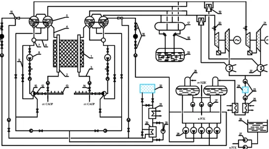
An overall sketch of the RBMK NPP can be seen in Fig. 1 and Fig. 2 and key system data are given in Tab. 1. Information is provided hereafter about system hardware relevant for safety technology.
1) Core 2) Water pipe 3) Reactor bottom plate 4) Group Distribution Header 5) Shield
6) Steam Drum 7) Steam Water Pipe 8) Reactor top plate 9) Refuelling machine 10) Reactor lid structure 11) Top reactor channel 12) Downcomers 13) Pressure Header 14) Suction header 15) Main Coolant Pump
Tab. 1 – Key parameters of the Smolensk-3 RBMK-1000 Key-parameters of core
Total Left Part Right Part
Power, MWth
3213 1629 1583 Flow rate Kg/s 10118 5158 5104
Number of FC 1568 794 774
Number FC with AA 90 45 45
Fuel Channel parameters
Full length, mm 18325
Number of channels 1660
Upper part diameter, mm and thickness, mm 95x5 Middle part diameter, mm and thickness, mm 88x4 Lower part diameter, mm and thickness, mm 60x5.5 Fuel rod overall length, m 3.46 Active core length, m 6.92 Spacer/support grids 20 per FC
Key dimensions of the down-comers
Diameter, mm and thickness, mm 325 x 15 Average length, m 29.15
Total volume, m3 47.7
Key dimensions of the Steam Header
Diameter, mm and thickness, mm 1020x60
Length, mm 21 080
Volume m3 17.3
Volume cylindrical part, m3 13.4
Key MCP thermal-hydraulic parameters (at 265 oC)
Q, m3/h (Kg/s) 8000±200 (2.22) Head, m 200±20 P inlet, bars 70.5 Power, MW 4.3±0.3 Speed, rpm 1000 Torque, N-m 39400
Key-parameters of Group Distribution Header
Diameter, mm and thickness, mm 325x15
Length, mm 5400
Design pressure, bar 100
Design flow, t/h 1700
Total volume of GDH, m3 16.5
Key-parameters of steam lines
Diameter, mm and thickness, mm 76x4
Average length, m 32
Design flow, t/h 40
Design pressure, bar 75
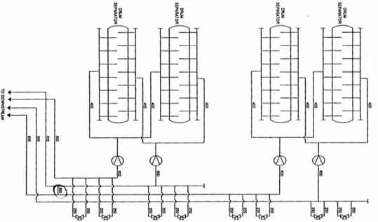
Key-parameters of Drum Separators
Number per reactor 4
DS length, m 30.98
DS internal diameter, m 2.6
DS volume, m3 150.2
Operation pressure, bar 68.9 Design pressure, bar 73.5 Nominal water level (above the central axis) mm 380±50
2.1. The Primary System
2.1.1. The pressure boundaryThe MCC consists of two loops, whose components are arranged symmetrically with respect to the vertical axis of the reactor. Each loop has two separator drums (1) (number in parenthesis refers to legend of Fig. 3, which separate the steam from the steam-water mixture exiting from the core block. The separator drums are horizontal cylindrical vessels interconnected both at the lower liquid level and at the upper steam level.
1-separator drum, 2-downcomers, 3-suction header, 4-suction piping of the MCP, 5-MCP, 6-pressure piping of the MCP, 7-bypass between headers, 8-pressure header, 9-group distribution header with flow limiter, check valve and mixer, 10-water bottom piping, 11-fuel channel before the core, 12-fuel channel within the core, 13-fuel channel above the core, 14-steam water pipes, 15-steam pipelines. 1-separator drum, 2-downcomers, 3-suction header, 4-suction piping of the MCP, 5-MCP, 6-pressure piping of the MCP, 7-bypass between headers, 8-pressure header, 9-group distribution header with flow limiter, check valve and mixer, 10-water bottom piping, 11-fuel channel before the core, 12-fuel channel within the core, 13-fuel channel above the core, 14-steam water pipes, 15-steam pipelines.
2 3 1 4 9 5 6 8 7 10 11 12 13 14 15 From ECCS
Fig. 3 – RBMK Main Circulation Circuit (MCC) flow diagram
In the bottom section of each separator drum (SD) a feed-water header is installed which provides through special mixers feed-water to the down-comer pipes. The separated water mixed with the feed-water reaches the suction header (3) through 24 down-comer pipes per each loop (2). The flow path continues through four suction pipes (4) connected to the four Main Circulation pumps (MCP). During normal reactor operation, only three pumps are operating in each loop, the fourth is a reserve. They are single stage vertical and centrifugal type.
From the MCP, water flows through pressure header pipes (6) to the pressure header, PH, (8). The suction and pressure headers are connected by bypass lines (7), provided with a gate and a check valve. The bypass ensures that natural circulation of the coolant takes place in case of main circulation pumps shut-off. From the pressure header (8) water continues through twenty two pipes to twenty two group distribution headers (GDH) (9). Mechanical filters are provided inside the pressure header while at GDH exit there are a flow limiter, a check valve and a mixer to which ECCS are connected.
Each GDH is connected to liquid pipes (10) leading to an average of forty-five fuel channels (12). The flow in each pipe, and therefore in each fuel channel (12), is set by isolation and control valves and is measured by a ball flow-meter. The steam-water mixture generated in the fuel channel flows through the steam-steam-water pipes (14) to the separator drums (1).
The elevations for the most important components of the MCC are presented schematically in Fig. 4. The total, top-to-bottom elevation of the primary system is over 30 m. The elevation driving the natural circulation loop, measured from the bottom of the core to the bottom of the separator drums, is ~ 21m. These large elevation heads determine the flow parameters of the system under natural circulation conditions.
From the separator drums the generated steam is directed to the turbines. Discharge steam from the turbines is accumulated in condensers, from there the condensate flows down through filters, heaters and deaerators to the main feed water pump and is finally returned to the separator drums.
The purification and the cooling of the primary cooling circuit water is performed by the Purification and Cooling System (PCS) which is an equivalent of the Chemical and Volume Control System (CVCS) in Western LWR. Part of the water is taken from the MCC, cooled down and filtered by a mechanical filter and by an ion-exchanger in the purification bypass. The treated water then joins the feed-water flow. The reactor also contains a number of channels for control rods and metering devices. These are cooled by a separate circulation system, which is called the Control Rod Cooling Circuit (CRCC).
The twelve down-comer pipes direct the water from the separator drums to the suction header, thus each of the two circulation loops contains twenty-four down-comers. The geometrical dimensions of each down-comer are given in Tab. 1. The suction headers collect water from the down-comers and supply coolant to four suction pipes in such a way a mixing of the water from the drum separator occurs. The geometrical dimensions of the suction headers are also given in Tab. 1.
For the forced circulation of cooling water through the RBMK reactor type CVN-8 (‘wet stator’ type) MCP are employed, Fig. 5. The CVN-8 type is centrifugal, vertical, single-stage pump with a sealed shaft. Four pumps are installed per each loop, three of them are normally in operation, and the fourth is kept as a reserve. The basic parameter of the pump at nominal conditions are reported in Tab. 1 and the pump curves for hot and cold water are given in Fig. 6, left and right sides, respectively.
Fig. 5 – The MCP for RBMK NPP.
1-service platform, 2- flywheel, 3- electric motor, 4- junction coupling, 5- support of electric motor, 6- foundation frame, 7- tank of the pump, 8- water outlet, 9- water inlet
0 500 1000 1500 2000 2500 3000 3500 4000 4500 5000 5 6 7 8 9 10 11 12 0 50 100 150 200 250 0 5 10 15 20 25 30 35 40 5 6 7 8 9 10 11 12 0 10 20 30 40 50 60 70 80 90 Q, 103m3/h Q, 103m3/h H, m N, kW N H η ∆h ∆h, al. η,% 1 - cavitation curve (Q-∆h) 2- power curve (Q-N)
3- hydraulic performance curve (Q-H) 4- MCP discharge–efficiency relationship (Q-η) 3 2 1 4 1. Cavitations curve Q-Dh 2. Power curve Q-N
3. Hydraulic performance curve Q-H 4. MCP discharge-efficiency relationship Q-h 0 500 1000 1500 2000 2500 3000 3500 4000 4500 5000 5 6 7 8 9 10 11 12 0 50 100 150 200 250 0 5 10 15 20 25 30 35 40 5 6 7 8 9 10 11 12 0 10 20 30 40 50 60 70 80 90 Q, 103m3/h Q, 103m3/h H, m N, kW N H η ∆h ∆h, al. η,% 1 - cavitation curve (Q-∆h) 2- power curve (Q-N)
3- hydraulic performance curve (Q-H) 4- MCP discharge–efficiency relationship (Q-η) 3 2 1 4 1. Cavitations curve Q-Dh 2. Power curve Q-N
3. Hydraulic performance curve Q-H 4. MCP discharge-efficiency relationship Q-h 0 5 10 15 20 25 30 35 40 5 6 7 8 9 10 11 12 72 74 76 78 80 82 84 86 88 90 92 0 1000 2000 3000 4000 5000 6000 7000 5 6 7 8 9 10 11 12 0 50 100 150 200 250 ∆h η Q 103 m3/h Q 103 m3/h H, m N, kW H N 1- cavitation curve (Q-∆h) 2- power curve (Q-H) 3- hydraulic performance curve (Q-N) 4- MCP discharge–efficiency relationship (Q-η)
1
4
2 3
Fig. 6 – RBMK MCP (CVN-8) performance data (left: high temperature conditions, 265 ºC; right: low temperature conditions, 90 °C)
The main function of each PH is to collect the water that comes from the pressure pipes connected to all main pumps exit and supply the coolant to the twenty-two GDH through twenty-two pipes. The pressure header has 1040 mm outside diameter and 70 mm thick walls.
The coolant is distributed to individual GDH by means of twenty-two pipes 325x15 mm. Each pipe has a manual control gate valve, a check valve and a mixer to mix (in case of accident) the cold water from the Emergency Core Cooling System (ECCS) and the hot water from the MCC. The check valve prevents back-flow from the fuel channels in case of failure of the pressure header. Mixers protect the MCC from thermal or hydraulic shocks. Flanges designed to prevent pipe whip in the event of a pressure surge are fixed to the structural beams of the plant and to a special framework
The coolant is supplied to the individual fuel channels via group distribution header, Fig. 2.6 which are horizontal cylinders, Tab. 3.1 The GDH are securely fastened to support structures to prevent any sliding in case of failure. Each header distributes coolant to 40-43 bottom water pipes. These pipes are provided with isolation and
control valves between the GDH outlet and the fuel channel inlet. Isolation and control valves are used to adjust channel flow on the basis of channel power. Flow rates can be controlled by varying the flow-area of the valves. This is achieved by manual operation from a separate room in the vicinity of the reactor block. The bottom water pipes leading into the reactor block drive the water into the fuel channels that remove the heat generated in the fuel assemblies. The liquid water starts to boil and the steam-water mixture flows from the top of the fuel channels by way of individual steam - water pipe to the separator drums. The exiting steam-water pipes include several bends. This aids in reducing gamma streaming.
1 – isolation and control valve, 2 – ball type flow-rate meter, 3 – coolant water pipe leading to the fuel channel, 4 – group distribution header
1 – isolation and control valve, 2 – ball type flow-rate meter, 3 – coolant water pipe leading to the fuel channel, 4 – group distribution header
a)
b)
Fig. 8 – Geometrical configuration of RBMK SD: a) overall view; b) cross section The separator drum has the following functions:
• separation of steam from the steam-water mixture flowing from the fuel channels,
• mixing of the separated water with feed-water, • storing of coolant for the MCC.
The steam water mixture arrives at the separator drum, through inlet pipes (9), (see Fig. 9 for numbering). A part of the steam is separated in the distribution compartments because the flow looses its kinetic energy in impact to the special plates (3).
Fig. 9 – Steam Drum – Component Specifications
This steam then penetrates the submerged perforated sheet (4) and the “barbotage” layer above it. Final separation occurs because of gravity force.
The separated steam goes through the perforations of the upper shields (5) into the steam-flow piping, the separated liquid flows downward from pipes at the bottom (13). The feed-water line has a nominal diameter of 500 mm (10). It enters into the separator drum at a 45 degree angle, and extends to a distribution header in the lower part of the drum. The feed-water is injected from the header (6) (7) to the down-comer (13) via jet spray nozzle in order to cool the water to be supplied to the MCP. Both the steam and liquid containing regions of the two separator drums are connected by number of pipes. The non uniform generation of power in fuel channels can lead to a non homogeneous steam-water distribution in the steam drum. This requires design features which serve to reduce both transverse and longitudinal variations of the steam content. This is accomplished by a submerged perforated sheet (4) with a 150 mm thick downward frame. A down-flow passages is provided between the frame and the drum wall for the part of the water, which penetrates the perforations together with steam. The down flow passages functions as a hydraulic lock against any penetrations of steam at the side of the perforated sheet. The sink is covered by safety plates spaced at 75 mm from the frame. Traverse and circumferential variations of pressure at the entrance of the steam pipes are reduced by a similar perforated shield in the upper part of the drum (5) and by inside diameter bushing installed in the steam outlet pipes. The two separator drums within each loop are interconnected both in the liquid and steam region, Fig. 10. There are five connecting (300x15) mm pipes in the steam