Degree of Philosophy Doctor in Space Systems and Technologies
Enhancing Transport Layer in
Satellite Systems:
Design and Development of an
Emulation Platform
by
Cesare Roseti
Supervisor Coordinator
The rapid growth of Internet applications (i.e., email, file transfer, remote access, web browsing, e-learning, e-banking, video-conferencing, etc.) is causing progressive congestion of telecommunication networks. Moreover, new classes of services includ-ing telemedicine, information dissemination, emergency support, disaster response and public information, may require broadband and untethered connectivity. There-fore, wireless access is gaining growing importance due to its intrinsic flexibility and ubiquity.
In such a context, the use of satellite systems represents an attractive option they can offer high transmission capacity and large coverage. In fact, a satellite system can guarantee broadband access to the global network in sparsely populated areas where deploying a terrestrial infrastructure remains unappealing or in regions where the deployment of terrestrial facilities remains impractical. Moreover, satellites can be integrated to terrestrial wireless (WiFi, UMTS, etc.) for enhancing mobile access to the Internet by both pedestrians and vehicles while it is often the only option for aeronautical and maritime users.
Most of broadband satellite systems are deployed at traditional geostationary or-bit (GEO). In this scenario, IP-based transfers must face some peculiar challenges. In particular, performance of Internet applications, being based on the “Transmis-sion Control Protocol” (TCP) at the transport layer, is strongly affected by several factors introduced by satellite systems (i.e., large latency, losses not due to conges-tion , high link asymmetry, etc.). Such factors make standard TCP inefficient over satellite links, resulting in poor performance.
The analysis and the design of an optimized transport layer for system includ-ing a satellite segment has been the object of the author’s Ph.D. program in the
period at the Computer Science Department of University of California Los Angeles (UCLA), has been carried out by the author in the frame of his Master’s thesis. Then, author has delved into such a research area over three years within National, EU and ESA founded projects and a stage period spent at both and TEC-SWS De-partment of the European Space Agency (ESA). Short or medium periods have been spent in external Universities as a visiting researcher to collaborate in joint activi-ties: [12/9/2004-16/8/2004] University of Siena, [3/11/2004-6/11/2004] University of Bologna, [20/3/2005-8/4/2005] Aristotle University of Thessaloniki (GR).
This thesis has a twofold aim: present all the achievements coming from the author’s research activity and, based on the collected experience, propose the design of a emulation platform optimized to test TCP/IP protocols over a likely satellite environment.
The work is organized in six chapters. Chapter 1 deals with basic notions con-cerning satellite systems. In particular, network architectures, services, standard and security aspects are briefly discussed. Chapter 2 summarizes main mechanisms regulating the standard TCP protocol. It aims at highlighting the main TCP pro-tocol characteristics, essential to understand the subsequent chapters which focus on issues of TCP in satellite-based environments. Chapter 3 offers a comprehensive analysis of TCP performance over satellite links. Along with the identification of both the main limitation and the proposed solutions to improve TCP performance, a vast gamut of analytical, simulation and experimentation results, coming from the author’s research activity, are presented. Chapter 4 collects all the outcomes of the author’s activity, focusing on the enhancement of the transport layer for Satellite-based Internet applications. Chapter 5 describes the main characteristics of an emulation platform, named “Satellite Network Emulation Platform” (SNEP), designed by author to reproduce the variable characteristics of a satellite network (DVB-RCS like) through an active emulation approach. Finally, conclusions are drawn in Chapter 6.
Most of the outcomes of the author’s research activities have been collected and discussed in the following publications:
1. M. Luglio, C. Roseti, M. Gerla, The Impact of Efficient Flow Control and OS Features on TCP Performance, Invited paper on ASSI Satellite Commu-nication Letter (Sat-Comm Letter), 9th edition, special issue on Multimedia
Satellite Communication, vol. III, n. 1, June 2004, pp. 1-9.
2. C.E. Palazzi,C. Roseti, M. Luglio, M.Y. Sanadidi, J. Stepanek,Enhancing Transport Layer Capability in HAPS-Satellite Integrated Architecture, Wireless Personal Communications (Kluwer Academic Publisher), vol. 32, n. 3-4, February 2005, pp. 339-356.
3. P. Chini, G. Giambene, D. Bartolini, M. Luglio, C. Roseti, Dynamic resource allocation based on a TCP-MAC cross-layer approach for DVB-RCS satellite networks, International Journal of Satellite Communications and Networking, Vol. 24, n. 5, Set/Oct. 2006, pp. 367-385.
4. C. Caini, R. Firrincieli, M. Marchese, T. De Cola, M. Luglio,C. Roseti, N. Celandroni, F Portont`ı, Transport Layer Protocols and Architectures for Ad-vanced Satellite Networks, International Journal of Satellite Communications and Networking, Vol. 25, n. 1, January 2007, pp. 1-26.
CONFERENCE & WORKSHOP
1. C. E. Palazzi, C. Roseti, M. Luglio, M. Gerla, M. Y. Sanadidi, J. Stepanek, Satellite coverage in urban areas using Unmanned Airborne Vehicles (UAVs), VTC spring 2004, 17-20 May 2004, Milan, Italy.
2. M. Luglio, C. Roseti, M. Gerla, TCP Performance over Satellite in Case of Multiple Sessions per Links using Efficient Flow Control and Real OS, 10th Ka and Broadband Communications Conference, Sept. 30th - Oct 2nd 2004, Vicenza, Italy, pp. 253-260.
3. G. Giambene, M. Luglio, C. Roseti, A cross-layer mechanism for efficient management of TCP-based traffic, in Proceedings of 23rd International Com-munication Satellite Systems Conference (ICSSC) and 11th Ka and Broadband Communications Conference, Rome, Italy, Sep. 2005.
lite Networks, in Proceedings International Workshop on Satellite and Space Communications (IWSSC), Siena, Italy, Sep. 2005.
5. P. Chini, G. Giambene, D. Bartolini, M. Luglio and C. Roseti, Cross-layer Management of Radio Resources in an Interactive DVB-RCS-based Satellite Network, in Proceedings 20th International Symposium on Computer and
In-formation Sciences (ISCIS), pp. 124-135, Istanbul, Turkey, Oct. 2005.
6. C. Roseti, G. Theodoridis, M. Luglio and N. Pavlidou, TCP driven CAC scheme for HAPS and Satellite integrated scenario, in Proceedings 1st
Inter-national Workshop on High Altitude Platform Systems (WHAPS), Athens, Greece, Sep. 2005.
7. C. Roseti, E. Kristiansen, TCP behaviour in a DVB-RCS environment, in Proceedings 24th AIAA International Communications Satellite Systems
Con-ference (ICSSC), San Diego, Jun. 2006.
8. M. Luglio and C. Roseti, Network Security and Performance Evaluation of ML-IPsec over Satellite Networks, in Proceedings 12th Ka and Broadband
Communications Conference, Naples, Sep. 2006.
9. M. Luglio, F. Mazzenga, C. Roseti, Analysis and Performance evaluation of integrated HAPS/Satellite architectures, First COST 297-HAPCOS Workshop, York, UK 26-27 October 2006.
10. D. Fanni, M. Luglio, C. Roseti, F. Zampognaro, A Cross-Layer based han-dover for TCP applications, 65thIEEE Vehicular Technology Conference (VTC),
Dublin, Ireland, Apr. 2007.
11. M. Luglio, N. Pavlidou, C. Roseti, G. Theodoridis, CAC-TCP cross-layer interaction in a HAPS-satellite integrated scenario,65th IEEE Vehicular
ence, Mar. 2007. BOOK
1. Ed. G. Giambene, Resource Management in Satellite Networks, Ed. Springer. C. Roseti, chapter editor of Chapter 9: Resource Management and Transport Layer.1
Un sentito ringraziamento ai miei genitori, che, con il loro incrollabile sostegno morale ed economico, mi hanno permesso di raggiungere questo traguardo.
Un ringraziamento speciale a Giusi per il suo sostegno continuo e sincero. I would like to thank my supervisor, Prof. Michele Luglio, for the guidance he provided throughout this work.
I would also like to thank Mr. Erling Kristiansen for all the fruitful and stimu-lating discussions.
Summary II
Acknowledgements VIII
1 Satellite systems: architectures, services and standards 1
1.1 Introduction . . . 1
1.2 The Satellite Networks . . . 2
1.3 Satellite Architectures . . . 3
1.4 Services & Applications . . . 5
1.4.1 Television & Video Services . . . 6
1.4.2 Interactive Services . . . 7 1.5 Standards . . . 7 1.5.1 DVB . . . 7 1.5.1.1 DVB-S & DVB-S2 . . . 11 1.5.2 IP over DVB . . . 13 1.5.3 DVB-RCS . . . 15 1.5.3.1 Resource management . . . 15
1.5.3.2 Bandwidth on Demand (BoD) . . . 16
1.6 Satellite Security . . . 18
2 TCP protocol 20 2.1 From OSI to the Internet architecture . . . 20
2.2 TCP services . . . 22
2.3 TCP header . . . 23
2.7 Congestion control and error recovery . . . 28
2.7.1 Slow Start (SS) . . . 28
2.7.2 Congestion Avoidance (CA) . . . 29
2.7.3 Retransmission TimeOut & Delayed ACKs . . . 30
2.7.4 Fast Retransmit & Fast Recovery . . . 32
3 Analysis on TCP over Satellite 34 3.1 Taxonomy . . . 34
3.2 Factors limiting TCP performance . . . 36
3.2.1 Latency . . . 36
3.2.2 Large bandwidth-delay product . . . 37
3.2.3 Connection Asymmetry . . . 38
3.2.4 Link availability & BER . . . 38
3.2.5 Real Operating System limitations . . . 38
3.3 TCP enhancements . . . 39
3.3.1 Window-based enhancements . . . 40
3.3.1.1 Window scaling . . . 40
3.3.1.2 Large initial window . . . 41
3.3.1.3 Byte counting . . . 41
3.3.1.4 Timestamp option . . . 41
3.3.1.5 Protect Against Wrapped Sequence (PAWS) numbers 42 3.3.2 Loss recovery enhancements . . . 42
3.3.2.1 NewReno option . . . 42
3.3.2.2 SACK option . . . 43
3.3.3 Connection start-up enhancements . . . 43
3.4 TCP Variants . . . 44
3.4.1 High-Speed TCP . . . 44
3.4.2 Scalable TCP . . . 44
3.4.3 BIC & CUBIC TCP . . . 45
3.4.4 TCP Vegas . . . 46
3.4.8 TCP Westwood . . . 49
3.4.9 TCP Real . . . 49
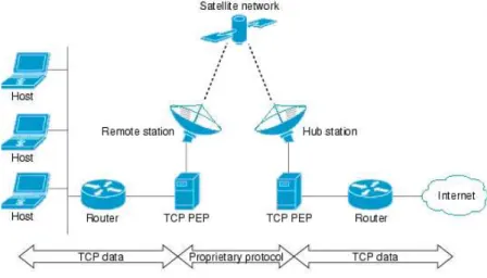
3.5 Performance Enhancing Proxies (PEPs) . . . 50
3.5.1 Spoofing . . . 50
3.5.2 Splitting . . . 51
3.6 Non-TCP Enhancements . . . 52
3.7 Analysis tools . . . 53
3.7.1 A simulation platform . . . 54
3.7.2 Network Engineering Platform . . . 57
3.7.3 Real Measurements . . . 57
3.7.4 Metric and comparison criteria . . . 57
3.7.4.1 Performance . . . 58
3.7.4.2 TCP friendliness . . . 58
3.7.4.3 Fairness & Channel Utilization . . . 58
3.7.4.4 Practical Implications . . . 59
3.8 TCP dynamics over satellite links . . . 59
3.8.1 TCP mechanisms over satellite links . . . 59
3.8.1.1 Impact of real Operating System features on TCP performance over satellite . . . 60
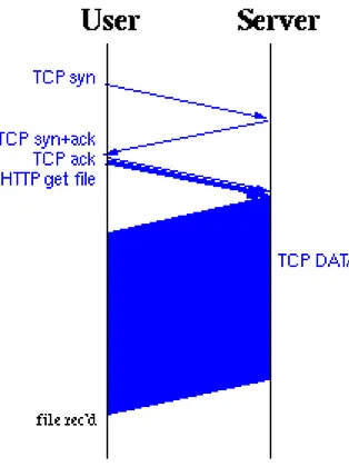
3.8.2 HTTP over satellite . . . 61
3.8.3 DVB-RCS impact on TCP performance . . . 64
3.8.3.1 DAMA performance . . . 65
3.8.3.2 An analytical model for TCP over DVB-RCS . . . . 65
3.8.4 Performance evaluation of TCP over DVB-RCS . . . 69
3.8.4.1 Emulation results . . . 70
3.8.4.2 Field Trials . . . 70
3.8.4.3 Simulation results . . . 71
4 Enhancing Transport Layer for Satellite-based Internet 79 4.1 Enhancing TCP in HAPS-Satellite Integrated Architecture . . . 79
4.1.3 Results . . . 87
4.2 Performance evaluation of ML-IPsec over satellite networks . . . 93
4.2.1 Conflict between IPsec and TCP PEP . . . 93
4.2.2 Possible solutions . . . 94
4.2.2.1 ML-IPsec . . . 95
4.2.3 Performance evaluation . . . 95
4.2.3.1 IPsec performance over TCP PEP . . . 97
4.3 A TCP-driven CAC scheme for a HAPS-Satellite Integrated Archi-tecture . . . 99
4.3.1 System architecture . . . 100
4.3.1.1 “Basic” CAC scheme . . . 101
4.3.2 CAC-TCP interaction . . . 101
4.3.2.1 CAC-TCP simulation model . . . 102
4.3.3 Channel model implementation . . . 105
4.3.4 Results . . . 106
4.3.4.1 Impact of the traffic load . . . 108
4.3.4.2 Impact of the average PER . . . 108
4.3.4.3 Impact of Blocking Probability Ratio among the QoS-classes . . . 111
4.3.4.4 Impact of the percentage of TCP users . . . 111
4.4 Dynamic resource allocation based on a TCP-MAC cross-layer approach112 4.4.1 A novel TCP-driven dynamic resource allocation scheme . . . 114
4.4.2 Analysis of the allocation process . . . 118
4.4.3 Performance evaluation . . . 120
4.5 A Cross-Layer based handover for TCP applications . . . 123
4.5.1 Reference scenario . . . 125
4.5.2 TCP behavior during handovers . . . 127
4.5.2.1 Transmission Errors . . . 127
4.5.2.2 Handover time (t∗) implications on RTO . . . 127
4.5.2.3 Generation of segment bursts . . . 128
4.5.4.1 Freezing TCP window . . . 130
4.5.4.2 Resetting of the sampled RTT . . . 130
4.5.4.3 Optimized handling of cwnd and sstresh . . . 130
4.5.5 Simulation . . . 130
4.5.5.1 Description . . . 130
4.5.5.2 Performance Evaluation . . . 132
4.6 Interworking between MANET and Satellite Systems for Emergency Applications . . . 135
4.6.1 MANET-Satellite interconnection . . . 136
4.6.1.1 Interface MANET-narrowband satellite system . . . 137
4.6.1.2 Interface MANET-broadband satellite system . . . . 138
4.6.2 Achievements . . . 138
4.6.2.1 Requirements . . . 139
4.6.2.2 Ad-Hoc Mesh Network Tests . . . 140
4.6.2.3 Voice service through broadband satellite terminal . 142 4.6.2.4 Data transfers through Globalstar terminal . . . 144
5 Design and Development of a Satellite Network Emulation Plat-form (SNEP) 146 5.1 Survey on emulation tools . . . 148
5.1.1 Examples of emulation platforms . . . 149
5.1.1.1 A Testbed for Upper Layers Performance Evaluation 150 5.1.1.2 Network Engineering Platform (NEP) . . . 151
5.2 The Satellite Network Emulator Platform . . . 153
5.2.1 Operational Environment . . . 155
5.2.1.1 Hardware Configuration . . . 156
5.2.1.2 Operating systems & software packages . . . 157
5.2.2 Technical description . . . 158
5.2.2.1 User Terminals . . . 160
5.2.2.2 Satellite Terminals . . . 161
6 Conclusions 165
1.1 Services & Applications provided by satellite systems . . . 6
2.1 TCP header bit flags . . . 24
3.1 TCP receive buffer size in common OS . . . 39
4.1 User terminal classes in terms of environment and average PER . . . 106
4.2 Expected value of the Inter-arrival time and Average traffic load cal-culation . . . 107
4.3 Average PER as function of the mobratio parameter . . . 110
4.4 Main simulation parameter values . . . 119
4.5 Trial achievements . . . 142
1.1 Satellite star architecture . . . 4
1.2 Satellite mesh architecture . . . 5
1.3 MPEG-2 reference system . . . 8
1.4 PES format . . . 8
1.5 TS format . . . 10
1.6 Mapping of Transport Stream, PES stream and elementary stream . . 12
1.7 Functional block diagram of the DVB-S system . . . 13
1.8 Entry points fot IP traffic over MPEG-2 . . . 14
1.9 Frame Time slotting . . . 16
2.1 OSI reference model . . . 21
2.2 Comparison between OSI and Internet architecture . . . 22
2.3 TCP encapsulation over IP . . . 23
2.4 TCP header . . . 24
2.5 TCP flow control scheme . . . 26
2.6 ACK for error control . . . 27
2.7 TCP sliding window mechanism . . . 28
2.8 Slow Start dynamics . . . 29
2.9 Congestion Avoidance dynamics . . . 30
2.10 TCP congestion window evolution . . . 33
3.1 TCP over satellite: taxonomy . . . 35
3.2 Maximum transmission rate vs. RTT . . . 40
3.3 TCP Spoofing application over satellite . . . 51
3.4 TCP Splitting architecture . . . 52
3.7 TCP congestion avoidance time . . . 61
3.8 Receiver Buffer Optimization . . . 62
3.9 HTTP/1.1 with pipelining file transfer . . . 64
3.10 NEP tests: RTT measurements . . . 71
3.11 RTT distribution over CRA scheme . . . 72
3.12 DAMA allocation dynamics (31 VBDC+ 1 CRA) . . . 73
3.13 RBDC capacity allocation dynamics . . . 74
3.14 RTT over RBDC . . . 75
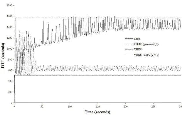
3.15 RTT evolutions with different DAMA schemes . . . 76
3.16 Throughput measurements for different DAMA schemes . . . 77
3.17 Normalized file transfer time . . . 78
4.1 Reference scenario . . . 82
4.2 Configuration of the simulated scenario . . . 85
4.3 Time to transmit a 5 MByte file from W to G . . . 87
4.4 Average throughput over a 230 sec transmission from W to G . . . . 88
4.5 Time to transmit a 5 MByte file from G to W . . . 89
4.6 Average throughput over a 230 s transmission from G to W . . . 89
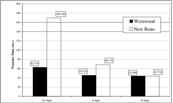
4.7 Sending window at the last sending/forwarding hop with no split, single split or double split . . . 91
4.8 Average time to transmit a 5 MBytes file from W to G with no split, single split or double split . . . 91
4.9 Performance achieved per proxy cache size. Transmissions from W to G, with a single proxy on T . . . 92
4.10 Performance achieved per proxy cache size. Transmissions from G to W, with a single proxy on T . . . 92
4.11 ML-IPsec in a TCP PEP satellite scenario . . . 96
4.12 Goodput measurements under different IPsec schemes (Packet size 1500 bytes) . . . 98
4.13 Transfer Time of a 5 Mbytes file under different IPsec schemes . . . . 99
mobility-groups, equal Blocking Probability (BP R1 = BP R2 = 1),
T CPperc = 100 . . . 109
4.16 Behavior of the system in terms of Average Throughput for different traffic conditions (L), uniform distribution of the users among the mobility-groups, equal Blocking Probability (BP R1 = BP R2 = 1),
T CPperc = 100 . . . 110
4.17 Blocking Probability decrease achieved by the CAC-TCP interaction, for 0.5 ≤ mobratio ≤ 1.5. T CPperc = 100 and BP R1 = BP R2 = 1,
traffic intensity equal to L = 10800 kbit/s . . . 111 4.18 Average Throughput increase achieved by the CAC-TCP interaction,
for 0.5 ≤ mobratio ≤ 1.5. T CPperc = 100 and BP R1 = BP R2 = 1,
traffic intensity equal to L = 10800 kbit/s . . . 112 4.19 System performance in terms of Blocking Probability for 0.5 ≤ BP R1 =
BP R2 ≤ 1.5, T CPperc = 100, mobratio = 1, and L = 10800 kbit/s . . 113
4.20 System performance in terms of Average Throughput for 0.5 ≤ BP R1 =
BP R2 ≤ 1.5, T CPperc = 100, mobratio = 1, and L = 10800 kbit/s . . 114
4.21 Average Throughput vs. Percentage of TCP connections for different of T CPperc values, BP R1 = BP R2 = 1, mobratio = 1, L = 11700 kbit/s115
4.22 Description of access delay contributions (DAMA allocations) . . . . 116 4.23 Comparison among allocated resources and cwnd trend versus time
(1 TCP connection, PER = 10−4) . . . 120
4.24 Comparison among allocated resources in the RTT vs. time (2 TCP connections, PER = 10−4) . . . 121
4.25 Comparison among average RTT values obtained with the following techniques: VBDC, CRA and the cross-layer scheme . . . 121 4.26 Average file transfer time versus PER (20 FTP transfers starting at
instants spaced of 5 s) . . . 123 4.27 Cross-layer access scheme: utilization and percentage of the average
utilization increase with respect to the CRA scheme (5 FTP transfers starting at instants spaced of 5 s, PER = 10−3). . . . 124
4.31 Simulator Object Oriented Simplified Model . . . 131
4.32 Throughput with t∗ = 2.5s and T W LAN = 8s . . . 132
4.33 DTT with TW LAN constant (7 s) . . . 133
4.34 DTT with t∗ constant (2.5 s) . . . 134
4.35 SAVION scenario . . . 136
4.36 MANET-Globalstar terminal interconnection . . . 137
4.37 MANET-VSAT interconnection . . . 138
4.38 Ad-hoc mesh network . . . 141
4.39 Test-bed configuration . . . 143
4.40 Test-bed in Trento . . . 144
5.1 UoB-CNIT testbed topology . . . 150
5.2 NEP emulator topology . . . 152
5.3 SNEP vs. Real System . . . 155
5.4 SNEP configuration . . . 157
5.5 SNEP general architecture . . . 159
Satellite systems: architectures,
services and standards
1.1
Introduction
The ever growing use of Internet applications (e.g., email, file transfer, remote access and web browsing) is causing progressive congestion of telecommunication networks. Moreover, new classes of services including telemedicine, information dissemination, emergency support, disaster response and public information, requires broadband and untethered connectivity. Therefore, wireless access is gaining growing impor-tance due to its intrinsic flexibility and ubiquity. For these reasons, satellite systems presents an attractive option since they offer high transmission capacity and large coverage [1][2]. In fact, a satellite can guarantee broadband access to the global network in sparsely populated areas where deploying a terrestrial infrastructure re-mains unappealing or in regions where the deployment of terrestrial facilities rere-mains impractical. Therefore, satellite extends mobile access to the Internet, in areas not covered by terrestrial wireless networks (WiFi, UMTS, etc.), for both pedestrians and vehicles, while it is often the only option for aeronautical and maritime users. Most broadband satellite systems are deployed at traditional Geostationary Earth Orbit (GEO).
The setting up of a communication link through satellites requires to carefully take into account the peculiar characteristics of the system, first of all the huge
distance between the terminal on ground and the spacecraft. Since the beginning of the satellite telecommunication age all the related problems have been approached and mostly solved or at least mitigated allowing to achieve ever easier feasibility and better degree of service along with cost reduction.
This chapter addresses the basic concepts concerning satellite telecommunica-tions providing as much as possible a complete, even though brief, overview on both architectures and standards that are envisaged in the research activity, reported in the rest of this thesis.
1.2
The Satellite Networks
A satellite network is composed of two segments: the ground segment and the space segment.
The ground segment is mainly composed of the gateway stations or Hub stations, the user terminals and the Network Operation Center (NOC). The NOC includes the Network Control Center (NCC) in charge of configuration management, capac-ity/bandwidth management, acquisition/synchronization control, performance man-agement, alarm manman-agement, security manman-agement, billing, and accounting. The space segment includes the satellite equipment and the communication payload.
Satellite systems can be classified on the basis of orbit: GEO, LEO, MEO, HEO or hybrid [3][4].
A GEO satellite is located at an altitude of approximately 36,000 km. GEO satellites can have a large footprint (approximately 1/3 on the world surface), and, in theory, just 3 satellites are sufficient to cover the entire world surface. On the other hand, at this altitude high latency presents a serious disadvantage (about 500 ms round trip delay).
LEO (Low Earth Orbit) satellites orbit around the world at an altitude varying between several hundreds of km and a few thousand km. In this case, the deployment of a constellation of several satellites is needed to achieve contiguous coverage, and efficient handover mechanisms must be implemented to allow service continuity. The propagation delay ranges from several ms up to 80 ms.
and LEO. Both LEO and MEO satellite systems have the advantage of lower prop-agation delays when compared with GEO system, but they are more complex to manage since both require continuous hand-off, dynamic routing algorithms and tracking mechanisms.
HEO (Highly Elliptical Orbit) satellites are located in elliptical orbits in which the Earth assumes the position of one of the two foci over planes inclined at 63.4◦
with respect to the equatorial plane. According to the Kepler’s second law, satellites in HEO orbits move slowly around the apogee looking “almost” stationary. As a consequence, HEO satellites cover high latitude regions very effectively with a good (high) elevation angle. Finally, hybrid systems use a combination of more than one type of orbit.
In this thesis, when not otherwise specified, networks based on GEO satellites are considered.
1.3
Satellite Architectures
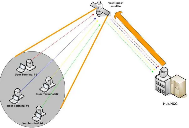
Most of the satellite communication systems are called “bent-pipe” to indicate that satellite simply acts as a signal repeater between two ground stations. Therefore, there is no data processing on board the satellite. On the other hand, some other satellite systems implement on-board processing (OBP) capabilities, which include demodulation, modulation, decoding, coding, packet switching, routing, etc.
An example of “bent-pipe” satellite system architecture is the Direct Broadcast Satellite (DBS), which supports only broadcast services (i.e. TV broadcasting). Instead, to support a full duplex Internet access, a possible solution is based on the use of dial-up telephone connections or by other terrestrial networks. Other solutions provide a return channel via satellite. This is the case of the DVB-RCS. In case of OBP, satellite networks appear like switching packet networks, where satellite switches packets among transmitting beams and receiving beams. Thus, in this case the satellite footprint is composed of multiple spot beams.
Two kinds of topology are usually supported by a satellite network: star and mesh. The former consists of a central hub station and a set of user terminals. The hub acts as the star center through which all the traffic transits; as a consequence
every pair of user terminals are physically interconnected through the hub thus needing a double hop on the satellite (large delay). In the latter topology the user terminals can be directly interconnected among each other, needing only one hop on the satellite, thus minimizing the use of the bandwidth and the delay (one hop). Hybrid configuration, with a subset of stations connected in full mesh mode and the others in star mode, is another possibility, which has trade-offs in performance.
Figure 1.1 shows a typical satellite star architecture, where all the ground ter-minals are directly connected to the Hub station via the transparent ”bent-pipe” satellite. The Hub/NCC station, acting as star center performs all the switch-ing/routing tasks. The terminals belonging to the satellite network communicate by a double-hop link: terminal 1-Hub and Hub-terminal 2.
Figure 1.1. Satellite star architecture
Figure 1.2 depicts a satellite mesh architecture, where the OBP satellite pay-load allows to cross-connect terminals through a multi-spot coverage. In particular, the on-board switching capability provides a direct connectivity among different coverage areas by a single-hop link.
Figure 1.2. Satellite mesh architecture
1.4
Services & Applications
There is not a real limitation to provide any service through a satellite network. Every kind of service and relative application can be implemented with satellite but taking into account specific performance. In fact, the propagation delay affects performance of real-time interactive service (e.g., voice, videoconference) but, on the other hand, the suitability to multicast operation makes satellite systems more efficient and cost effective. In particular, both real-time and store and forward services, both fixed and mobile services, both narrow band and wideband services, unicast, multicast, and broadcast services are currently provided.
Satellite systems represent a very attractive solution for a large set of applications including content delivery, data/voice communications and Internet over Satellite. In some case, satellite is the most efficient solution (i.e. provision of broadcast services in a large geographic scale), while in other cases is recommended especially for strategic or economic matters (i.e. Internet access or communications in isolated and sparsely populated areas). The main service/application classes can be classified
as in the Table 1.1.
Service Application
Messaging E-mail
Chat Paging
On-line Info Retrieval PC Networking Data Base Access Remote Login Telephony Voice Sms Video-communication Videophone Videoconference Video-information Tele-medicine Tele-education Broadcasting Analog TV Digital TV HD-TV Analog Radio Digital Radio
Table 1.1. Services & Applications provided by satellite systems
1.4.1
Television & Video Services
The main service provided via satellite over the years has been surely TV broad-casting. In fact, United States, Japan and Europe have largely adopted satellites for distribution of TV programs. In Europe, the Digital Video Broadcasting Project (DVB) worked on designing global standards for the delivery of the digital television [5]. In this frame, DVB-S system for digital satellite broadcasting was developed in 1993 [6]. In general, satellite networks are far more suitable than the terrestrial networks for data broadcasting (i.e. web-casting, network news, TV programs, etc) thanks their ability to cover large areas optimizing radio resources. Furthermore, video distribution applications can usually tolerate delay (but not excessive jitter).
1.4.2
Interactive Services
Interactive services concern both voice and data communications. Voice commu-nications are particularly affected by the propagation delay imposed by the GEO satellite systems, which degrades the quality of the interactive communication. On the other hand, most of the current data communications are based on TCP/IP protocol stack, and among these a large part requires reliable data transmission and runs TCP as transport protocol. When using TCP over satellite networks, performance is influenced negatively by 3 factors:
• Long link delay means long round trip time (RTT) for the mechanisms con-trolling sending rate and congestion management.
• TCP acts defensively to variation in available bandwidth, potentially leading to under-use of communication resources.
• TCP assumes all packet losses are due to congestion. A packet lost due to errors on the link induces TCP to reduce its sending rate unnecessarily, thus wasting resources and/or reducing performance.
The issue of TCP performance over satellite is still a big challenge in satellite network research and it is strongly coped along this thesis.
1.5
Standards
Satellite systems are mostly based on proprietary standards, both in terms of hard-ware and services. This section focuses on Digital Video Broadcasting (DVB) stan-dards, largely referred in the author’s research activity.
1.5.1
DVB
The DVB system [5] specified by the European Broadcast Union (EBU) is based on the cell-oriented packet transmission system defined by ISO/IEC 13818-1 MPEG-2 Systems Standard [7]. MPEG-2 Systems Standard provides the means of multi-plexing several types of multimedia information into one Transport Stream (TS)
that can be transmitted over a variety of transmission media. Figure 1.3 shows the MPEG-2 reference system.
Figure 1.3. MPEG-2 reference system
The basic component of MPEG-2 System is known as ”Elementary Stream” (ES). A programme (i.e. TV programme or DVB track) contains a combination of Elementary Streams, typically one for video, one for audio and one for metadata. ESs are generated by video, audio and data encoders. Each ES is an input for an MPEG-2 processor (i.e. video compressor or data formatted), which assembles data into a stream of ”Packetised Elementary Stream” (PES). A PES packet is a variable sized block (up to 65536 bytes) including a 6-bytes protocol header. A PES is usually organized to contain an integer number of ES units.
A PES packet structure is shown into Figure 1.4.
Figure 1.4. PES format
The PES header starts with a 3 byte start code, followed by a 1 byte stream ID and a 2 byte length field respectively. The next field contains the ”PES indica-tors” that provide further information about the stream to assist the decoder at the receiver. Such indicators are:
• Fixed bits (2 bytes);
• PES Scrambling Control (2 bytes) which defines whether scrambling is used and, in case, the chosen scrambling method;
• PES Priority (1 byte) which indicates priority of the current PES packet; • Data Alignment Indicator (1 byte) which indicates if the payload starts with
a video or audio start code;
• Copyright information (1 byte) which indicates if the payload is copyright protected;
• Original or Copy (1byte) which indicates if the PES belongs to the original ES.
A flags field completes the PES header. Each flag defines one of the following optional fields, which (if present) are inserted before the start of the PES payload:
• Presentation Time Stamp (PTS) and possibly a Decode Time Stamp (DTS) which are used to synchronize a set of elementary streams as well as to control the rate they are replayed by the receiver;
• Elementary Stream Clock Reference (ESCR);
• Elementary Stream rate which indicates the rate at which the ES was encoded; • Trick Mode which indicates a not “normal” ES (i.e. after DSM-CC has
sig-naled a replay);
• Copyright Information which is set to 1 to indicate a copyright ES; • CRC which may be used to monitor errors in the previous PES packet; • PES Extension Information which may be used to support MPEG-1 streams. The information in the PES header is, in general, independent on the transmis-sion method. Finally, the PES packet payload includes the ES data, and (if needed) a stuffing byte is placed before the payload.
The sequence of variable-length PES composes a Program Stream (PS) that assumes the use of error-free transmission channels (storage). In addition to the PS, MPEG-2 System Standard specifies another multiple stream: the Transport Stream (TS). TS assumes the use of transmission channels (such as in broadcasting and
telecommunications) where errors occur and consists of relatively short fixed length TS packets. The MPEG-2 specification makes possible to convert PS streams into TS streams. Consequential, a PES packet can be divided into segments that, in turn, can be placed in the data section of TS packets. Each TS packet has a fixed length of 188 bytes. This length is highly compatible with ATM cell lengths and has been chosen because of its applicability to efficient and robust error-correction coding. The most important information in the TS header is the packet identifier (PID) that can identify about 8000 types of packets in a 13-bit field. The format of the transport packet is shown in Figure 1.5.
Figure 1.5. TS format
Each MPEG-2 TS packet envisages 184 bytes of payload data prefixed by a 4 bytes header. The header has the following fields:
• Synchronization Byte which is a well-known sequence of bits (0x47=0100 0111);
• Three bit-flags indicating how the payload should be processed, – The first flag indicates a transport error;
– The third flag indicates transport priority bit;
• A 13-bit Packet Identifier (PID) which is used to uniquely identify the stream which the packet belongs to. Some PID values are predefined and are used to indicate streams of control information;
• A 2-bit Transport Scrambling Control field which is used by conditional access procedures for the encryption of some TS packets;
• A 2-bit adaptation field control indicating the type of the TS payload config-uration,
– 01 - no adaptation field, payload only; – 10 - adaptation field only;
– 11 - adaptation field followed by payload; – 00 - RESERVED for future use;
• Continuity Index (4 bits) which is used to control continuity in the Transport Stream (the value is cyclical incremented).
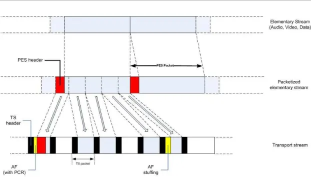
The adaptation field can contain various types of information such as splice countdown used to indicate Programme Clock Reference (PCR) and edit points. It is also used as stuffing; that is, when the final section of a PES packet is placed in a TS-packet payload, dummy data is added to ensure a fixed-length TS packet. In general a PES packet spans several TS packets. When a PES packet is starting the “payload unit start indicator” bit is set to 1, which means that the first byte of the TS payload contains the first byte of the PES packet header. Only one PES packet can start in a single TS packet. As seen above, TS header also contains the PID so that the receiver can accept or reject PES packets at a high level without leading to a hard processing. An example of how PES packets are placed in the data section of TS packets is shown in Figure 1.6.
1.5.1.1 DVB-S & DVB-S2
DVB-S has been conceived for primary and secondary distribution (Fixed Satellite Service, FSS) and Broadcast Satellite Service (BSS), at present mostly operated in
Figure 1.6. Mapping of Transport Stream, PES stream and elementary stream
the Ku band (11/14 GHz) [6]. This standard is designed to provide a direct reception from the satellite (Direct-To-Home, DTH) for both a single user with an integrated receiver-decoder and a collective access. In particular, the DVB-S goal is to adapt the baseband signal from the output of the MPEG-2 transport multiplexer to the satellite channel characteristics. Since DTH services via satellite are particularly affected by power limitations, robustness against noise and interference has been taken as the main design objective.
The satellite channel adaptation concerns the types of modulation and coding schemes to be adopted to meet the target quality of the signal. The quality target is the provision of a “Quasi Error Free” (QEF) channel, corresponding to a Bit Error Rate (BER) ranging from 10−10to 10−11at the input of the MPEG-2 demultiplexer).
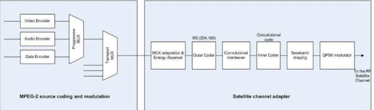
The processes involved in this adaptation are transport multiplex adaptation and randomization for energy dispersal, outer coding (i.e., Reed-Solomon), convolutional interleaving, inner coding (i.e., punctured convolutional code), base-band shaping, and modulation (Figure 1.7). The randomization is applied to make the RF spec-trum approximate a white noise process. The channel coding is applied through three steps: outer code Reed-Solomon (204, 188, T = 8), convolutional interleaving with the aim to randomize burst errors, and convolutional coding with a variable
code rate (1/2, 2/3, 3/4, 5/6, and 7/8). Gray-coded QPSK modulation with abso-lute mapping (no differential coding) is adopted. Base-band signal is square-root-raised-cosine-filtered with a roll-off factor of 0.35. The DVB approach offers a good degree of flexibility. A 38 Mbit/s data flux could contain eight standard definition television (SDTV) programs, four enhanced definition television programs (EDTV), or one high definition television (HDTV) program, all with associated multichannel audio and ancillary data services. The maximum data rate for a data stream is typically about 38 Mbit/s accommodated in a 33-MHz satellite transponder.
Figure 1.7. Functional block diagram of the DVB-S system
DVB-S2 [8] is the second generation DVB. In the new scheme, which modifies the satellite channel adaptation block only, adaptive modulation and coding (ACM) have been introduced. In particular, low density parity check codes (LDPC) have been selected with Bose-Chaudhuri-Hochquenghem (BCH) code-block length 64,800-bit (or 16,200-bit) periodic structures that facilitate parallel decoding with about 50 decoding iterations. Available coding rates are 1/2, 3/5, 2/3, 3/4, 4/5, 5/6, 8/9, and 9/10. Moreover, five modulation formats, all optimized to operate over nonlinear transponders, have been selected: BPSK (1 bit/s/Hz), QPSK (2 bit/s/Hz), 8PSK (3 bit/s/Hz), 16APSK (4 bit/s/Hz), and 32APSK (5 bit/s/Hz). Then, three roll-off factors are allowed: 0.35, 0.25, and 0.20 (DVB-S: only 0.35). With the new standard, an optimization of spectral resources in the order of 30-40
1.5.2
IP over DVB
Within MPEG-2 TS, it is possible to carry defined data containers in addition to the audio and video [9]. These data containers can be used to realize new data services
or to carry IP datagrams.
The DVB specification for data broadcasting [5] defines three different ways of inserting data into the MPEG-2 transport stream. According to the functional block diagram shown in Figure 1.8, there are three possible entry points for IP data traffic over MPEG-2:
(i) Data packets can be encapsulated and carried inside the PES packets intended for video and audio streams. This method is referred as Data Streaming. (ii) Data packets can be carried inside the section packets defined for system
in-ternal tables in DSM-CC. This method is called Multiprotocol Encapsulation (MPE).
(iii) An adaptation layer protocol can segment data packets directly into a sequence of cells. This method is called Data Piping.
Figure 1.8. Entry points fot IP traffic over MPEG-2
Methods (i) and (ii) are offered by MPEG-2 as standard. In both cases, the segmentation function is performed automatically. The third method of transferring datagrams (data piping) needs an explicit segmentation and reassembly layer.
All three methods involve a certain overhead, which stems from the header fields and the fact that IP datagrams usually do not come in multiples of 184 bytes (TS packet size). The total overhead for a transmission depends on the packet length distribution and the encapsulation method selected. The observed overhead for MPE is typically between 13 and 15 per cent [10].
1.5.3
DVB-RCS
The success of the DVB standard due to its capability to transmit huge quantity of data in a very flexible way, with consequent availability of technology at low cost, extends its field of applicability beyond the transmission of only data information. In addition, the compatibility with IP protocol allows the processing of the IP packet in the DVB stream. As a consequence, first the use of DVB for one-way systems (DVB IP with return channel on terrestrial networks) has been introduced. They are based on the use of the DVB flow in the forward link (data received through the same equipment utilized for digital TV), while the return link is exploited through terrestrial networks (i.e., ISDN, PSTN).
A two-way standard based on DVB was introduced with return channel on satel-lite (DVB-RCS), which allows bidirectional communications up to 2 Mbit/s in the return link and shares the bandwidth on a Multi Frequency Time Division Multiple Access (MF-TDMA) discipline [11][12].
1.5.3.1 Resource management
A certain number of adjacent temporal slots (with the same frequency) are arranged into a frame, with a fixed structure. A frame is composed of different kinds of slots. Data must be placed into a Traffic burst format (TRF) slot. The overall frequency channels available and their time slotting at frame level is announced from the HUB via the forward link on a Service Information (SI) table, as shown in Figure 1.9.
This information is acquired by terminals in the setup phase, and it is important for the transmission synchronization.
The coordination is in charge to the Network Control Center (NCC) which pre-pares a Burst Time Plan (BTP) so that every slot has an “owner”, and a terminal
Figure 1.9. Frame Time slotting
is only authorized to transmit in its own slots. How the BTP is scheduled is related to the DAMA scheme discussed in next section.
Several frames are grouped into a super-frame, which contains all frames with the same BTP structure. DVB-RCS supports the use of ATM or optionally MPEG-2 as transport layer above the physical layer.
The BER required for return channel is of about 10−7 taking into account the
mandatory FEC coding. Turbo coding is an option; thus, systems using that FEC coding either would have a better error performance or would need smaller antennas for the same performance.
1.5.3.2 Bandwidth on Demand (BoD)
DVB-RCS supports a Demand Assignment Multiple Access (DAMA) scheme in the return link [11][12]: the NCC assigns bandwidth as response to explicit requests (BoD) coming from RCSTs by announcing in the forward link, for every frame, the Terminal Burst Time Plane (TBTP) on the basis of both the request category and the Service Level Agreements (SLAs) between operator and customers. According to the DVB-RCS standard, RCSTs send their resource requests to the NCC. The NCC, after performing the access control routines, assigns to each RCST a group of bursts (i.e. the related time slots), each of them characterized by a frequency, a bandwidth, a start time and a duration in the form of the TBTP. The DVB-RCS
standard allows fixed or dynamic time slot allocations according to five different schemes.
1. Continuous Rate Assignment (CRA): CRA is a fixed and static allocation of resources after an initial set-up phase with a negotiation between the RCST and the NCC. With CRA, a given number of time slots are continuously as-signed to an RCST every super-frame until that RCST sends the assignment release message.
2. Rate-Based Dynamic Capacity (RBDC): RBDC is rate capacity dynamically requested by the RCST to the NCC. Each request is absolute, corresponding to the full rate currently being requested, overrides all previous RBDC requests from the same RCST, and shall be subject to a maximum rate limit directly negotiated between the RCST and the NCC.
3. Volume-Based Dynamic Capacity (VBDC): VBDC is volume capacity dynam-ically requested by the RCST to the NCC. These requests are cumulative (i.e. each request shall add to all previous ones from the same RCST), indicating a total number of traffic slots that are needed to transmit all data currently available in the MAC queue. These slots can be shared among several super-frames. MAC parameters are the minimum and the maximum VBDC capacity that can be assigned to an RCST. VBDC is the default mode in DVB-RCS. 4. Absolute Volume-Based Dynamic Capacity (AVBDC): AVBDC is volume
ca-pacity dynamically requested by the RCST to the NCC; AVBDC requests are absolute (i.e. each request replaces the previous ones from the same RCST) and indicate a total number of traffic slots that can be assigned in several super-frames. AVBDC is used for loss recovery in the VBDC mode.
5. Free Capacity Assignment (FCA): FCA is volume capacity that shall be as-signed to RCSTs from capacity that would be otherwise unused by CRA, RBDC and (A)VBDC methods. The term ’free’ in FCA refers to ’spare’ sys-tem capacity. Such a resource assignment shall be automatic, not involving any request from the RCST. Capacity assigned in this category is intended as a bonus capacity that can be used to reduce delays for any traffic category.
Every super-frame, slots are allocated in an orderly manner based on both the request category (i.e., priority order: CRA → RBDC → (A)VBDC → FCA) and the Service Level Agreements (SLAs) between operator and customers.
1.6
Satellite Security
The level of security, in a broad sense, that a satellite system can ensure relies both upon its characteristics and upon the number of expedients that it is possible to implement [13]. The following peculiar characteristics of satellite systems assume a meaningful importance in providing security.
• The coverage area, typically quite extended, allows the network to serve a large number of users even in remote, isolated and impervious locations, where usually terrestrial infrastructures are not deployed (either for economic or fea-sibility reasons) and where typically some office that requires isolation for confidentiality can be located.
• The broadcast peculiarity of the satellite signal represents an advantage for key distribution to a large set of users spread over the territory. Moreover, this characteristic does not imply the capability to receive information for anybody. In fact, to receive just the electromagnetic signal from just one satellite a highly directional antenna is usually necessary and as a consequence accurate pointing is needed; then, even though the signal is received, to decode information may not be so easy requiring compliance with the adopted air interface. When omnidirectional antenna are adopted on the ground terminal, no pointing is necessary but the decoding information aspect still applies.
• The high latency limits performance of security protocols implementation in-troducing significant inefficiency if frequent key distribution updating is re-quired, as for example in the multicast scenario [14].
• Facilities and equipment are well localized and not spread over the territory and thus extremely easy to be garrisoned. As a consequence, the unauthorized access to telecommunication resources is practically impossible.
• The practical absence of an open, diffused standard, which actually represents a weakness from market penetration point of view, represents an additional factor of security. In fact, to be able to not only receive the electromagnetic signal but to decode information, it is necessary to be authenticated by the NCC. The authentication process cannot be performed if the utilized standard is not known.
• Both the space segment and terrestrial segment equipment are extremely re-liable increasing the confidence for the satellite user about security in terms of service continuity. This feature encourages the use of satellites for secure services that, in most of the cases dealing with, for example, human safety and disaster relief, need also the highest degree of survivability.
TCP protocol
The TCP/IP protocol suite, derived from OSI reference model, is a set of protocols that allow terminals from different networks and with different software/hardware characteristics to communicate each other. Such protocols are developed in lay-ers, with each layer being responsible for a different aspect of communications. TCP/IP is commonly characterized as a 4-layer structure [15]. This chapter deals with the features and the standard implementations of the transmission control protocol (TCP) [16], which is one of the transport layer protocols.
2.1
From OSI to the Internet architecture
The network architecture known as Open System Interconnection (OSI) and defined by the International Standards Organisation (ISO) represents a theoretical reference in designing of the real network architectures (i.e., Internet). In particular, the OSI architecture is based on seven layers, as shown in Figure 2.1. This layering on more levels makes the design more simple and facilitates the realization of eventual mod-ifications. In fact, every layer takes care of specific aspects of the communication. Furthermore, every layer provides some service to the upper level, taking advantage of those provided from the lower levels.
The real communication is performed at the physical layer, whereas the upper levels set up a virtual communication with their correspondent. A message that must be exchanged between two terminals crosses all the layers (up to the physical layer)
Figure 2.1. OSI reference model
and each layer elaborates the data and adds in the head to the message an header (encapsulation technique). When the message arrives to the terminal receiver, each layer removes the corresponding header and uses it for the own tasks. The Internet architecture presents only four layers, whose correspondences with OSI architecture are shown in Figure 2.2.
The functionalities of each layer can be briefly resumed as follows:
• Data Link Layer includes the device drivers and the corresponding Network Interface Card (NIC).Then, it allows the interfacing to the physical media. • Network Layer has in charge both addressing and routing functions. It manage
the transfer of the IP packet around the network.
• Transport Layer sets up, keeps and releases a connection between the two ends of a communication. Moreover, it has in charge the segmentation and reassembly of the messages.
Figure 2.2. Comparison between OSI and Internet architecture
• Application Layer provides services that are frequently requested by the ap-plication.
2.2
TCP services
The transport layer provides a flow of data between two terminals for the application layer above. In the TCP/IP protocol suite, two very different transport protocol are defined: TCP (Transmission Control Protocol) [16] and UDP (User Datagram Protocol) [17].
Even though TCP and UDP use the same network layer (IP), TCP provides a totally different service to the application layer than UDP does.
TCP provides a connection-oriented, reliable, byte stream service.
Three functions can be identified in the TCP protocol: flow control, congestion control and error recovery. The flow control scheme allows an efficient exchange of data not exceeding the capacity of the receiver buffer; it is based on the advertised window (rwnd) indicating the free space on the receiver buffer [15]. The conges-tion control scheme governs how TCP avoids and reacts to network congesconges-tion. In particular, TCP uses a variable, called congestion window (cwnd), to control the
amount of data sent at a certain time. Therefore, the network status is probed by gradually increasing cwnd until congestion is experienced and cwnd is resized [19]. The minimum between cwnd and rwnd determines the transmission window. TCP uses cumulative acknowledgements (ACKs) to notify the sender on the last segment correctly received and in order [15]. Then, the timeout expiration at the sender or the receipt of duplicated ACKs indicates the loss of the corresponding segment, thus triggering one of the implemented error recovery schemes.
2.3
TCP header
The TCP data are encapsulated into an IP datagram, as shown in Figure 2.3. Then, TCP segment is composed, in turn, of a header and a data payload. Herein, header fields are briefly described, introducing also some basic information on the TCP specific control schemes (i.e. flow control) that are treated in depth in the following.
Figure 2.3. TCP encapsulation over IP
The normal size of the TCP header is 20 bytes, without additional options. Each TCP segment contains the source and destination port number to identify the sending and receiving application (see Figure 2.4). These two values, along with the source and destination IP addresses in the IP header, uniquely identify each connection. The combination of an IP address and a port number is called “socket”. The sequence number field identifies the first byte of data in the TCP segment. The sequence number is a 32-bit unsigned number then ranging from 0 to 232− 1.
When a new connection is being established, the SYN flag is turned on and the sequence number field contains the “initial sequence number” (ISN), chosen by this host for this connection. Since every byte that is exchanged is numbered, the acknowledgement number refers to the next sequence number that TCP expects to receive. This field is valid only if the ACK is on. The header length gives the length of the header in a 32-bit words. This is required because the length of the options field can be variable (TCP is constrained to a 60-bytes header). TCP flow
Figure 2.4. TCP header
control is provided by each end host advertising a window size. This is the number of bytes, starting with the one specified by the acknowledgment number field, that the receiver is willing to accept. It is a 16-bit field, limiting the window to 65535 bytes. The checksum refers to the whole TCP segment: the TCP header and the TCP data. This is a mandatory field that must be calculated and stored by the sender, and then verified by the receiver. Finally, the urgent pointer is valid only if the URG flag is set. Such a pointer is a positive offset that must be added to the sequence number field of the segment to yield the sequence number of the last bytes of urgent data. TCP’s urgent mode is a way for the sender to transmit emergency data.
The meaning of the six flag bits in the TCP header is shown in Table 2.1. URG The urgent pointer is valid
ACK The acknowledgement number is valid
PSH The receiver should pass this data to the application as soon as possible RST Reset the connection
SYN Synchronize sequence numbers to initiate a connection FIN The sender is finished sending data
2.4
TCP buffers
A buffer is needed at each end of the TCP connection and such a buffer pair plays an important role in terms of achievable performance. The maximum amount of data in transit in the network is constrained by the bandwidth-delay product, that is, the product of the bottleneck link bandwidth and Round Trip Time (RTT). In order to prevent packet loss due buffer overflow, the receiver needs enough buffer space to store all incoming data. For this purpose, TCP implements a mechanism called “Advertised Receive Window” [15]. This mechanism limits the maximum number of bytes in flight in a given time to the free space in the receiver buffer. In other words, the maximum transmission rate achievable is governed by the following formula:
Max T x Rate ≤ Advertised Receive W indow
RT T (2.1)
Therefore, buffer size is fundamental to achieve good performance in case of high latency and broadband links. Studies demonstrates that optimal performance requires a receive buffer size at least twice the Bandwidth-Delay Product (BDP) [18]. Real Operating System (OS) implementations have a default and a maximum size for these buffers that in most cases can be manually changed. Some user-space applications can set TCP buffer size; otherwise the default value is used.
2.5
Connection establishment and termination
TCP is a connection-oriented protocol, which uses a mechanism, called three-way handshake [15], that envisages of three steps:
1. the “client” sends a SYN segment specifying the port number of the “server” and its Initial Sequence Number (ISN);
2. the “server” responds with its SYN segment containing its ISN and also ac-knowledges the client’s SYN;
To terminate a connection TCP needs four messages. In fact, since the TCP connection is full-duplex, each end-points must shut down independently by a closing message and the corresponding acknowledgement (“half-close”) [15].
2.6
Flow control
TCP performs a flow control aiming to provide to the application layer a byte-based, in-order (without errors or duplications) stream of data. TCP general scheme is based on the following steps:
• a sending application writes data into a sending buffer through the socket; • TCP groups bytes into the TCP packet structure and send them through the
network;
• When TCP packets reach the receiver, an ACK is generated and sent back to the sender. Simultaneously, data bytes are accommodated into a receiving buffer.
• A receiving application reads bytes from the sending buffer through the socket. Such a scheme is depicted in Figure 2.5
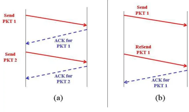
TCP has been conceived to be self-clocking by using ACKs receptions as an indication that a segment has left the network (successfully received) and then there is space to accommodate one more segment (Figure 2.6a). In case ACK is not received within a timeout interval, TCP assumes that packet has been dropped somewhere and retransmits it (Figure 2.6b). This is the basic TCP error control mechanism (Section 2.7.3). TCP manages the start up of clocking and adjusts continuously it by its congestion control scheme (Section 2.7).
Figure 2.6. ACK for error control
In addition to the ACK-clocking mechanism, TCP flow control uses a sliding window mechanism [15] to adapt the transmission rate to the available bandwidth in the channel while not exceeding the capacity of the receiver buffer. Then, TCP flow control manages the shift of such a sliding window over the “segment space”, while congestion control (Section 2.7) manages its growth/reduction and the receiver advertises a maximum window size, namely advertised window.
In principle, TCP window represents the amount of unacknowledged data, in bytes, that the sender can have in transit towards the receiver. In general, the sliding window moves to the right. In particular, the left edge advances to the right when sent data are acknowledged; as a consequence the right edge moves to the
right as the receiver empties space in the buffer, as shown in Figure 2.7.
Figure 2.7. TCP sliding window mechanism
2.7
Congestion control and error recovery
TCP congestion control manages the sliding window increase/decrease. In the last 25 years, TCP congestion control and error recovery schemes have been subject to continuous enhancements coping with the even new communication environments and traffic characteristics. The concepts of Slow Start (SS), Congestion Avoid-ance (CA) and Fast Retransmit-Fast Recovery (FR-FR) algorithms are presented in [19][20], while the Retransmission TimeOut (RTO) mechanism is described in [15][21].
TCP congestion control is mainly based on two state variables: • the Congestion Window (cwnd);
• the Slow Start Threshold (ssthresh).
In more details, cwnd limits the amount of unacknowledged data a TCP sender can inject in the network. Some implementations keep its value in unit of bytes, while others in unit of full-sized segment. On the other hand, ssthresh represents the switching point between the SS and CA phases.
2.7.1
Slow Start (SS)
To prevent congestion problems, TCP sender probes the state of the network by gradually increasing its sliding window until congestion occurs and packet drop as a
consequence. After the three-way handshake is completed and connection is estab-lished, TCP sets its cwnd to Initial Window (IW) value, less or equal to 2 Sender Maximum Segment Size (SMSS), and runs the SS algorithm. SS is characterized by an exponential increase of the cwnd as reaction of the ACK receptions (Figure 2.8). For instance, TCP sender initially sends one segment and waits for the correspond-ing ACK. When it receives the ACK, it sends two segments. In general, durcorrespond-ing the whole SS, TCP sender increases cwnd by SMSS bytes for each ACK received:
cwndi+1 = cwndi+ SMSS. (2.2)
Then, as a function of the elapsing time, the cwnd growth can be expressed as follows:
cwnd(t) = 2RT Tt (2.3)
The slow start phase terminates when the cwnd exceeds the ssthresh or when a packet is lost.
Figure 2.8. Slow Start dynamics
2.7.2
Congestion Avoidance (CA)
When cwnd gets over ssthresh value, the CA algorithm is triggered [20]. During CA, for every incoming non-duplicate ACK, the cwnd in bytes is update according to the following rule:
cwndi+1= cwndi+
SM SS cwndi
(2.4) Accordingly, the cwnd growth over time is:
cwnd(t) = t − tssthresh
RT T + ssthresh (2.5)
The above formulas can be interpreted as a cwnd increase of 1 SMSS per RTT (Figure 2.9).
Figure 2.9. Congestion Avoidance dynamics
2.7.3
Retransmission TimeOut & Delayed ACKs
TCP uses a retransmission timer to ensure data delivery in the absence of any feedback from the remote data receiver. The duration of this timer is referred to as RTO (retransmission timeout). To compute the current RTO, a TCP sender makes use of two state variables:
• SRTT (smoothed RTT); • RTTVAR (RTT variance).
Another important role is also played by the timer granularity, indicated in the following as G. The rules governing the computation of SRTT, RTTVAR, and RTO are described in [21] and listed in the following:
1. Until an RTT measurement has been made for a segment sent between the sender and receiver, the sender sets RTO to 3 s, though the “backing off” on repeated retransmission still applies.
2. When the first RTT measurement R is made, the TCP sender sets SRTT equal to R, RTTVAR to R
2 and RTO to SRT T + max(G,K · RT T V AR),
where K = 4.
3. When the next RTT measurement R0 is available, a host sets
RT T V ARnew = (1 − β) · RT T V ARold+ β · |SRT Told− R0| (2.6)
SRT Tnew = (1 − α) · SRT Told+ α · R0 (2.7)
where the subscripts “new” and “old” indicate the new updated value and the old one, respectively. Moreover, usually α = 1
8 and β = 14.
4. After the computation, a host updates RTO following the relation
RT O = SRT T + max(G,K · RT T V AR) (2.8) On the basis of the computation of the RTO value, the following procedure manages the retransmission timer:
1. For each data transmission (or retransmission), if the timer is not running, it starts so that it will expire after RTO seconds.
2. When all outstanding data has been acknowledged, the retransmission timer is turned off.
3. When a non-duplicated ACK is received, the timer is restarted so that it will expire after RTO seconds.
When the retransmission timer expires:
1. The earliest segment that has not been acknowledged by the TCP receiver is retransmitted.
2. The host performs the back-off operation by setting RTO to RT O ·2 (“back off the timer”). This RTO value is maintained until either a fresh RTT estimate is available or a new RTO expiration occurs.
Many TCP’s acknowledge only every Kth segment out of a group of segments
arriving within a short time interval; this policy is known generally as delayed ACK [23]. The data-sender TCP must measure the effective RTT, including the additional time due to delayed ACK’s, or else it will retransmit unnecessarily. Thus, when delayed ACK’s are in use, most Berkeley-derived implementations of TCP measure only 1 RTT per window.
2.7.4
Fast Retransmit & Fast Recovery
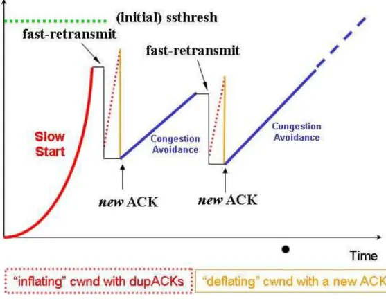
In early TCP implementations (old TCP Tahoe) [22], whenever a loss occurred the sender had to wait for a timeout interval before retransmitting the missing packet. Since the length of this timeout is conservative, the idle time after a loss event grows continuously. Also, after a retransmission timeout the sender wastes bandwidth re-entering the “Slow Start” phase. To mitigate such problems TCP Reno (1990) introduced the ”Fast Retransmit” and ”Fast Recovery” algorithms [15][19] which allow the TCP sender to retransmit a lost segment before timeout. In fact, since TCP generates duplicate acknowledgements (dupACKs) [15], the Fast Retransmit algorithm considers the arrival of three dupACKs as a clear indication that a segment has been lost and retransmits it immediately. In addition, the Fast Recovery algorithm interprets the dropped packet as an indication of network congestion and reduces the congestion window. In detail, The fast retransmit and fast recovery algorithms are usually implemented together as follows:
• After receiving 3 dupACKs, TCP sender: – Retransmits the lost segment; – Sets ssthresh = currentcwnd
2
– Sets cwnd = ssthresh , and ndupacks = 3; – Sets cwnd = cwnd + ndupacks;
– + + ndupacks;
– Transmits new segments, if allowed; • If new ACK arrives:
– ndupacks = 0; – Exit fast recovery.
Figure 2.10 shows a typical time evolution of the congestion window for TCP Reno as a function of RTT.
Analysis on TCP over Satellite
The core of TCP/IP protocol stack has been designed and developed from the mid 1970’s coping with issues usually encountered in wired networks [20][24]. Therefore, some of the assumptions of the first TCP design fail in satellite links leading to poor performance [25][26][27][28][29].
This chapter points out the factors impacting TCP performance over satellite links by analyzing TCP dynamics in related environments. Furthermore, all main strategies to counteract the satellite constraints are classified and analyzed.
The overall analysis is enriched by results, coming from both simulation and real measurements, achieved by author.
3.1
Taxonomy
A large number of solutions have been proposed in the literature to improve TCP performance over satellite links. Nevertheless, the constant upgrading of satellite standard, the technology development and the definition of new network topolo-gies lead at arising new problems to face, and accordingly new solutions become necessary. In addition, there are many solutions originally proposed for different environments (i.e., Wireless terrestrial networks), that, although partially, improve TCP dynamics over satellite links.
Figure 3.1 proposes a taxonomy, which classifies both problems and solutions for TCP over satellite into groups and sub-groups.