Scanning, and Transmission Electron Microscopy Study in Man
Giovanna Orsini, Tonino Traini, Antonio Scarano, Marco Degidi, Vittoria Perrotti, Marcello Piccirilli, Adriano Piattelli
Department of Stomatology and Oral Science and Dental School, University of Chieti-Pescara, Via Dei Vestini, 31, 66100 Chieti, Italy
Received 29 March 2004; revised 13 July 2004; accepted 24 August 2004
Published online 11 May 2005 in Wiley InterScience (www.interscience.wiley.com). DOI: 10.1002/jbm.b.30196
Abstract: Biological interactions occurring at the bone– biomaterial interface are critical for long-term clinical success. Bio-Oss威 is a deproteinized, sterilized bovine bone that has been extensively used in bone regeneration procedures. The aim of the present study was a comparative light, scanning, and electron microscopy evaluation of the interface between Bio-Oss威 and bone in specimens retrieved after sinus augmentation procedures. Under light microscopy, most of the particles were surrounded by newly formed bone, while in a few cases, at the interface of some particles it was possible to observe marrow spaces and biological fluids. Under scanning electron microscopy, in most cases, the particle perimeter appeared lined by bone that was tightly adherent to the biomaterial surface. Transmission electron microscopy showed that the bone tissue around the biomaterial showed all the phases of the bone healing process. In some areas, randomly organized collagen fibers were present, while in other areas, newly formed compact bone was present. In the first bone lamella collagen fibers contacting the Bio-Oss威 surface were oriented at 243.73 ⴞ 7.12° (mean ⴞ SD), while in the rest of the lamella they were oriented at 288.05ⴞ 4.86° (mean ⴞ SD) with a statistically significant difference of 44.32° (p< 0.001). In the same areas the intensity of gray value was 172.56ⴞ 18.15 (mean ⴞ SD) near the biomaterial surface and 158.71 ⴞ 21.95 (mean ⴞ SD) in the other part of the lamella with an unstatistically significant difference of 13.79 (pⴝ 0.071). At the bone– biomaterial interface there was also an electron-dense layer similar to cement lines. This layer had a variable morphology being, in some areas, a thin line, and in other areas, a thick irregular band. The analyses showed that Bio-Oss威 particles do not interfere with the normal osseous healing process after sinus lift procedures and promote new bone formation. In conclusion, this study serves as a better understanding of the morphologic characteristics of Bio-Oss威 and its interaction with the surrounding tissues. © 2005 Wiley Periodicals, Inc. J Biomed Mater Res Part B: Appl Biomater 74B: 448 – 457, 2005
Keywords: Bio-Oss威 particles; electron microscopy; humans INTRODUCTION
Insufficient bone volume in the posterior maxilla can produce problems in implant insertion.1–7 Augmentation procedures are used to provide a sufficient volume of bone for implant placement. Several different materials have been proposed for sinus augmentation procedures, but it is still not clear which graft materials are clinically most suitable for bone regeneration.6,7Autologous bone is believed to be the gold standard, but its main disadvantages are a limited availability, a tendency to undergo partial resorption, the need for an
additional surgery under general anesthesia, and the associ-ated morbidity (limping, anesthesia, paresthesia, residual de-fects).6,7These facts have produced a quest for a bone sub-stitute that could be used in bone regeneration techniques. Bone is a dynamic tissue that undergoes continuous remod-eling.8 The biological interactions occurring at the bone– biomaterial interface are critical for long-term clinical suc-cess.8 Bio-Oss威 is a xenograft consisting of deproteinized,
sterilized bovine bone with 75 to 80% porosity and a crystal size of approximately 10m in the form of cortical granules; it has a natural, nonantigenic porous matrix with 0.25–1.00-mm particles.9 –24This material is chemically and
physically identical to human bone; it is reported to be highly osteoconductive and to show very low resorbability.6 –16The large-mesh interconnecting pore system facilitates angiogen-esis and migration of osteoblasts. The goals of biomaterials research for bone regeneration is the continuous development
Correspondence to: A. Piattelli (e-mail: [email protected]).
Contract grant sponsors: the National Research Council (C.N.R.), Rome, Italy, the Ministry of Education, University and Research (M.I.U.R.), Rome, Italy, and AROD (Research Association for Dentistry and Dermatology), Chieti, Italy
© 2005 Wiley Periodicals, Inc.
and improvement of biocompatible substances that induce a predictable, controlled, guided, and rapid healing of the in-terfacial tissues.25 The events occurring after biomaterials
implantation comprise two components: the response of the host to the biomaterial, and the behavior of the material in the host.26,27 It has been reported that the initial host response
after HA particles implantation is generally marked by an inflammatory reaction.28 During this early postimplantation
phase, inflammatory cells and proteins accumulate in the vicinity of the particles, and these proteins adsorb onto the implant surface.28
Light microscopy (LM) provides the most important in-formation about the presence of bone or soft tissue contact, but it does not give ultrastructural information about the true arrangements at the interface.29 –38
In transmission electron microscopy (TEM) studies, an elec-tron dense granular layer at the interface with HA and titanium has been reported.37,38 The origin and organic composition of
this layer remain obscure, and it has been speculated that it may play an important role in HA– bone interactions.28This
interfa-cial layer comprises various bone proteins such as sialoprotein, ␣2-HS-glycoprotein, osteocalcin, osteopontin (OPN), perhaps
proteoglycans, and most likely other as-yet unidentified compo-nents.39 – 44This electron-dense layer has been reported to stain
darkly with alcyan blue, thus suggesting a proteoglycan content similar to that found in natural cementing substance.28An
elec-tron-dense layer was also found at the interface between root-dentin and newly formed regenerative periodontal tissues in animal models.45 On a ultrastructural level, in the bone–HA
interface there was apparently no direct contact between bone and implant crystals because they were interconnected by a very thin nonmineralized organic bone matrix only observable by high power transmission electron microscopy.37De Lange and
Donath observed in a TEM study a 20 –100-Å thick electron dense layer at the bone–HA interface resembling the lamina limitans of bone and of the inner walls of the osteocytes lacu-nae.34These authors studied the interface between the HA and
bone at the ultrastructural level, demonstrating mineral crystal-lites of bone adjacent to the implant surface at a distance of 200 Å.34 Previous studies indicated that this organic layer could
represent a mucopolysaccharidic film. In an in vitro experiment using cell cultured with Bio-Oss威 particles it was possible to observe an electron-dense layer at the interface with a darker line on the biomaterial side.46Moreover, a recent histological
eval-uation of Bio-Oss威 showed that some proteins might physically infiltrate the superficial layer of the particles, participating in the cellular events of host cells.47
The aim of the present study was a comparative light, scanning electron microscopy (SEM) and transmission elec-tron microscopy analysis of the bone–Bio-Oss威 interface in specimens retrieved after sinus augmentation procedures.
MATERIALS AND METHODS
Twelve patients participated in this study: eight males and four females, with ages between 44 and 72 years, with a mean
of 54 years. Six patients received unilateral maxillary sinus augmentation and six were treated with bilateral sinus lift. In all the patients dental implants were then placed after 6 months. The protocol was approved by the Ethic Committee of our University, and all patients signed a written informed consent. Inclusion criteria were presence of a maxillary par-tial (unilateral or bilateral) edentulism involving the premo-lar/molar areas, and the presence of a residual alveolar ridge height between 3 and 4 mm. Exclusion criteria were smoking, patients with systemic diseases or maxillary sinus pathology, patients with recent extractions in the involved area, and patients in which primary stability could not be established. At the initial visit, all patients received a clinical and occlusal examination, and periapical and panoramic radiographs and computerized axial tomography scans were performed.
Surgical Protocol
Under local anesthesia, a crestal incision slightly toward the palatal aspect throughout the entire length of the edentulous segment was performed, supplemented by buccal releasing incisions mesially and distally. Full thickness flaps were elevated to expose the alveolar crest and the lateral wall of the maxillary sinus. Using a round burr under cold (4 –5°C) sterile saline irrigation, a trap door was made in the lateral sinus wall. The door was rotated inward and upward with a top hinge to a horizontal position. The sinus membrane was elevated with curettes of different shapes, until it became completely detached from the lateral and inferior walls of the sinus.
Whenever a small tear was noted in the membrane, it was repaired with a collagen membrane (Biogide, Geistlich, Wol-husen, Switzerland). The Bio-Oss威 particles, ranging from 0.25–1.00 mm (Geistlich, Wolhusen, Switzerland), were mixed with sterile saline solution in a proportion of 20:1, and carefully packed in the sinus cavity using a plugger. The quantity of Bio-Oss威 needed for each augmentation varied from 3– 4.5 g. Another membrane (Biogide, Geistlich) was positioned against the packed sinus window. The mucoperi-osteal flap was then replaced and sutured with multiple hor-izontal mattress sutures. Amoxicillin (1 g two times per day) was prescribed for 1 week and analgesics as required. Sutures were removed 2 weeks after surgery. Postsurgical visits were scheduled at monthly intervals to check the course of healing. The sinus was allowed to heal for 6 months, and then im-plants were placed. At the time of implant surgery, 18 bone cores were harvested from the crestal wall using a 5-mm diameter trephine under a cold (4 –5°C) sterile saline irriga-tion.
Specimen Processing
Light Microscopy (LM). Twelve of the 18 specimens
were immediately fixed in 10% buffered formalin and pro-cessed to obtain thin ground sections with the Precise 1 Automated System (Assing, Rome, Italy). The specimens were dehydrated in a ascending series of alcohol rinses and
embedded in a glycolmethacrylate resin (Technovit 7200 VLC, Kulzer, Wehrheim, Germany). After polymerization the specimens were sectioned along their longitudinal axis, which corresponds to the long axis of bone cores retrieved using a high-precision diamond disc. Half of each specimen was then prepared for SEM observation (in the next section specifications will follow). The other half was sectioned with the diamond disc at about 150m, and ground down to about 30m with a specially designed grinding machine (Precise 1, Assing, Rome, Italy). The sections were stained with acid fuchsin and toluidine blue.
Six of the 18 retrieved cores were washed in a saline solution and quickly immersed in 2.5% glutaraldehyde and 2.5% formaldehyde (prepared from fresh paraformaldehyde) buffered at pH 7.2 with 0.1 M sodium phosphate for 4 h at room temperature and left overnight at 4°C. After washing for 1 h in the buffer alone, the specimens were decalcified using 4.13% EDTA (Sigma). They were postfixed in 1% cacodylate buffered osmium tetroxide for 1 h, dehydrated in graded concentrations of ethanol, and embedded in LR White resin (London Resin, Berkshire, UK). These specimens were cut with glass knives on a Reichert Jung Ultracut E ultrami-crotome and stained with toluidine blue. The 1 m-thick sections obtained were then prepared for observation under SEM and TEM (specific sections will follow).
All the obtained semithin sections were observed in nor-mal transmitted light under a Leitz Laborlux Microscope (Laborlux S, Leitz, Wetzlar, Germany) connected to a high resolution video camera (3CCD, JVC KY-F55B), and inter-faced to a monitor and PC (Intel Pentium III 1200 MMX). This optical system was associated with a digitizing pad (Matrix Vision GmbH) and a software package with image capturing capabilities (Image-Pro Plus 4.5, Media Cybernet-ics Inc., Immagini & Computer Snc Milano, Italy).
Scanning Electron Microscopy (SEM). The 30m-thin
ground sections obtained from the 12 specimens fixed with formalin as well as the 1m-thick sections obtained from the six decalcified specimens were prepared for SEM observa-tion. They were etched with a 0.1 N of HCl solution for 90 s, treated with trypsin (80 U/mL) at a pH of 7.4 for 15 min at 37°C, and were gold coated with sputter (Emitech K 550, Emitech Ltd, Ashford, Kent, UK). The SEM investigation (LEO 435 Vp, LEO Electron Microscopy Ltd, Cambridge, UK) was performed using both the secondary electron mode (SE1) and quadrant back-scattering detector (QBSD) to im-prove the understanding of the relationship between Bio-Oss威 particles and bone. Under SEM, the SE1 images were used to evaluate the topographic relation among Bio-Oss威 particles and surrounding bone, while the QBSD images were used to analyze the relationship among Bio-Oss威 particles and surrounding bone on the basis of atomic number differ-ences.
Transmission Electron Microscopy (TEM). Selected ar-eas of the 1 m-thick sections obtained from 6 of the 18 retrieved specimens were prepared for TEM evaluation. In
particular, areas randomly chosen at the Bio-Oss/surrounding tissue interface and in the near proximity of the particles were selected and trimmed for ultrathin sectioning. Ultrathin sec-tions of the selected areas were prepared with a diamond knife, mounted on copper grids, and stained with 4% uranyl acetate and lead citrate for examination in a JEOL 1010 transmission electron microscope operated at 60 kV (JEOL Ltd., Tokyo, Japan). The TEM was connected with a Digital Camera MegaView III equipped with the Analysis Imaging System GmbH (Munster, Germany).
A total of 15 regions contacting the perimeter of Bio-Oss威 particles were examined for intensity of gray values and collagen fibers orientation analysis, using the specific proto-col that will follow.
Specific Procedure. The digitized images from TEM
were stored in tif format with N⫻ M ⫽ 1024 ⫻ 768 grid of pixels for a 16 bit. Each cell referred to as a pixel in the grid was assigned a value between 0 and 255. The method used for quantification both of collagen fiber orientation and stain intensity involved the semiquantitative digital densitometry of the gray areas by software image analysis (Sigma Scan Pro 5, SPSS Inc., Chicago, IL). To ensure accuracy, the software was calibrated for each experimental image. Pythagorean theorem was used for distance calibration, which reports the number of pixels between two selected points: the start and end of the measurement scale bar was present on each TEM image. The linear remapping of the pixel values was used to calibrate the intensity of images. Only the first bone lamella contacting the Bio-Oss威 particles was measured evaluating both the collagen fibers orientation and the intensity of the gray values. In particular, two areas (A and B) were evaluated (see Tables). The areas A and B were determined inside the first bone lamella contacting Bio-Oss威 particles: the area A was at the interface with the Bio-Oss威 particle while the area B was in the opposite site at the interface with the second bone lamella.
Statistical Analysis. All data were analyzed by means of the computerized statistical package Primer 4.02 (McGraw Hill Inc., New York). The collagen fibers orientation and gray values were both compared using Student’s t test. Statistical differences were considered significant when p ⬍ 0.05. In particular, in the first bone lamella contacting Bio-Oss威 par-ticles were measured both the intensity of gray values and collagen fibers orientation. The data were inferred using unpaired t test as reported in Tables I and II.
RESULTS Light Microscopy
Most of the particles were surrounded by newly formed mature, compact bone with well-organized osteons, while few particles were in contact with biologic fluids and marrow spaces (Figures 1–3). In some fields, osteoblasts were
ob-served in the process of apposing bone directly on the particle surface. No gaps were present at the bone–particles interface, and the bone seemed to be always in close contact with the particles. No inflammatory cell infiltrate was present around the particles or at the interface with bone. In the ground thin sections of 30 m osteocyte lacunae of the graft particles seemed filled by osteocytes, may be due to the interposed osseous tissue. Indeed, no clear presence of osteocytes was detected in sections that were thinner (1m thick).
In all the semithin sections, some regions of the Bio-Oss威 particles appeared to be cemented by newly formed bone, which presented both features of woven and mature bone. Some areas were in contact with marrow spaces. At high magnification, the bone around the Bio-Oss威 particles often presented wide osteocytic lacunae. The Haversian canals appeared to be colonized by capillaries and cells: in some of the Haversian canals it was possible to observe the presence of acid fuchsin positive, not yet mineralized, material lining their inner surface. In the most peripheral bone the osteocytic lacunae appeared to be always filled by osteocytes, while the most central ones appeared to be filled by small cells with morphologic and staining features different from the osteo-cytes. Only in a few cases the osteocytic lacunae were empty. Bio-Oss威 particles presented marked staining differences from the host bone, and had a lower affinity for the stains. Only in a few areas surrounding the particles it was possible to see multinucleated giant cells.
Scanning Electron Microscopy
In most cases, the particle perimeter appeared to be lined by bone that was tightly adherent to the surface of the biomate-rial (Figures 4 and 5). Only in some very small areas, bone appeared to be detached from the particle surface. Near the
particles, woven bone was more represented than lamellar bone. Nevertheless, when lamellar bone was present, the particle surface was not easily distinguished from the sur-rounding bone lamellae. The back-scattering image showed the same degree of mineralization of the bone in between the particles and the surrounding lamellar bone.
Transmission Electron Microscopy
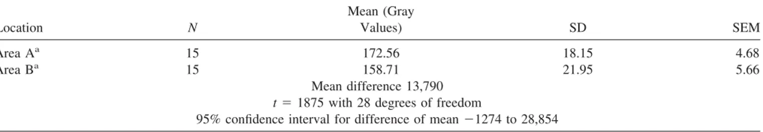
There were only a few areas where it was possible to find an inflammatory reaction, and the majority of the Bio-Oss威 particles were surrounded by newly deposited bone (Figure 6). Qualitative estimation of the osseous tissue surrounding the particles demonstrated all the phases of the bone-healing process. In some areas there were collagen fibrils randomly disposed and newly formed osseous tissue while in other areas, compact bone was seen. In the collagen-rich mineral-ized areas, it was possible to observe the characteristic peri-odicity of the collagen fibers. The mean thickness of these fibrils was 60 nm. Where the bone appeared more compact, a “lamellar” appearance was observed. The collagen fibers were oriented at 243.73 ⫾ 7.12° (mean ⫾ SD) when con-tacting Bio-Oss威 surface, while the rest of the lamella colla-gen fibers were oriented at 288.05⫾ 4.86° (mean ⫾ SD) with a statistically significant difference ( p⬍ 0.001) (Table I and Figures 7 and 8). The intensity of gray value measured inside the first bone lamella was 172.56⫾ 18.15 (mean ⫾ SD) near the biomaterial surface and 158.71⫾ 21.95 (mean ⫾ SD) in the other part of the lamella with an unstatistically significant difference ( p⫽ 0.071) (Table II and Figure 9). The perimeter of Bio-Oss威 particles showed an electron-dense layer similar to “cement lines” and “laminae limitantes,” which provided an interface with variable morphology (Figure 10). The par-ticles were in contact with either healthy or degenerating
TABLE I. Unpaired t-Test for Collagen Fibers Orientation in the First Bone Lamella Contacting Bio-Oss
Location N
Mean (Collagen Fiber
Orientation in Degrees) SD SEM
Area Aa 5 243.73 7.12 3.18
Area Ba 5 288.05 4.86 2.17
Mean difference⫺44,320 t⫽ 11,496 with 8 degrees of freedom
95% confidence interval for difference of mean⫺53,210 to ⫺35,430 aStatistically significant p⬍ 0.001.
TABLE II. Unpaired t Test for Intensity of Gray Values in the First Bone Lamella Contacting Bio-Oss
Location N Mean (Gray Values) SD SEM Area Aa 15 172.56 18.15 4.68 Area Ba 15 158.71 21.95 5.66 Mean difference 13,790 t⫽ 1875 with 28 degrees of freedom
95% confidence interval for difference of mean⫺1274 to 28,854 a
cells, bone tissue, organic fluids and cell debris. In some areas, this interfacial zone was a well-delimited thin line, while in other areas, it was a thick irregular band. Moreover, in some parts it was interrupted, and in other parts it was presented by peaks and curves.
Internally, the Bio-Oss威 particles showed the presence of an unorganized amorphous tissue and some empty osteocyte lacunae (Figure 11).
DISCUSSION
Clinically, the high osteoconductive property of Bio-Oss威 has been widely demonstrated.1,3,4,6,9,11Numerous
investiga-tors have recognized that Bio-Oss威 is an appropriate syn-thetic material resembling the hydroxyapatite crystals of bone that can be employed in basic and clinical research for the treatment of osseous defects and maxillary sinus augmenta-tion.1–23 The present study confirms the preexisting data because in all patients treated with implants after maxillary sinus augmentation procedures using Bio-Oss威 a great clin-ical response was obtained. Radiographic evaluations of the osseointegrated implants were taken immediately after their placement, at 3 and 6 months, showing that all the implants were well integrated in the augmented maxillary sinus. Despite the clinical success of Bio-Oss威 has been often corroborated by histologic and histomorphometric find-ings,2,5,10,12,15–23very few ultrastructural features have been described in the published literature.47,48The purpose of our evaluation is to increase the knowledge of the clinician that
Figure 1. Light micrograph showing that some of the Bio-Oss姞 par-ticles are in contact with bone, while others are surrounded by bio-logical fluids and marrow spaces. Original magnification: Toluidine blue and acid fuchsin 10⫻. [Color figure can be viewed in the online issue, which is available at www.interscience.wiley.com.]
Figure 2. Light micrograph: at this magnification, it is possible to observe the presence of a close and tight contact between Bio-Oss姞 and the osseous tissue. Original magnification: Toluidine blue and acid fuchsin 16⫻. [Color figure can be viewed in the online issue, which is available at www.interscience.wiley.com.]
Figure 3. Light micrograph: in this area, the bone particle is in con-tact with marrow spaces. Original magnification: Toluidine blue and acid fuchsin 16⫻. [Color figure can be viewed in the online issue, which is available at www.interscience.wiley.com.]
Figure 4. Scanning electron micrograph: at .702 K times magnifica-tion it is possible to observe a Bio-Oss姞 particle in contact with bone that can be either lamellar or woven bone.
use biomaterials to understand the interactions that occur in close proximity of the Bio-Oss. The microstructure and the delicate porous morphology of Bio-Oss威 particles probably enhance the effectiveness of this material.47,48 Generally, bone regeneration has to be induced in advance so that patients can receive dental implants. After 6 months the investigated xenograft did not show signs of resorption and was well integrated in the host tissues, confirming the behav-ior reported by recent literature.49It has been reported that the long-lasting presence of Bio-Oss威 particles, completely in-corporated with bone, might strengthen the osseous tissue mass, creating a dense cancellous network, thus improving its ability to withstand loading forces transmitted by implants.49 An increased scientific knowledge of the morphological characteristics of such a biomaterial could help the clinicians for its proper use. The multiple evaluation of the interface
Figure 5. Scanning electron micrograph: at 5.2 K times magnifica-tion, the Bio-Oss姞 particle is in contact with bone that appears composed by multiple lamellae not very well organized.
Figure 6. Transmission electron micrograph: it is possible to observe a direct contact between the Bio-Oss姞 particle and the bone (arrows). The interface between bone and Bio-Oss姞 appears well delimited, but irregular, with variable thickness. Bar⫽ 5m.
Figure 7. Trasmission electron micrograph showing the area of anal-ysis for collagen fibers orientation and gray values. Bar⫽ 2m.
Figure 8. Intensity plots of the gray values of the collagen fibers inside the first bone lamella. Area A near the surface of Bio-Oss姞. Area B in the rest of the first bone lamella.
using LM, SEM, and TEM show how the same structure can appear depending on the selected examination method. Fea-tures of Bio-Oss威 surrounding tissues were described to guide clinicians in understanding the healing process that occurs around Bio-Oss. In particular, using the three pro-posed methods, Bio-Oss/neighboring tissue interface is out-lined under different aspects. Whereas LM demonstrates a close contact between Bio-Oss威 and bone, SEM clearly shows the morphological nature of this newly generated bone and the high resolution of TEM allows the detection and evaluation of the Bio-Oss/bone interface.
Moreover, to investigate the structure of the first layer of newly formed bone contacting Bio-Oss威 particles, we have applied a novel software that characterizes gray value and collagen fibers organization of the bone surrounding the particles. The presented data reveal that this bone does show
features similar to peripheral and preexisting osseous tissue, thus indicating the good osteoconductive properties of the xenograft.
A recent study has discussed the possibility that Bio-Oss威 microstructure may affect the deposition of osteogenic pro-teins and therefore benefit bone formation on the surface.47In
particular, some growth factors and bone matrix proteins may infiltrate into the superficial layer of Bio-Oss威 by passing its porous architecture, or bind directly to its hydroxyapatite crystals by virtue of protein such a OPN.47 Osteopontin, a
mineral-binding glycoprotein, has been identified as a major component of the lines demarcating bone/biomaterial inter-face, and with other molecules, is particularly concentrated in the cement lines.39 Cement lines are classified as being a
matrix–matrix interface found between two spatially and temporally distinct matrices: they can, for instance, demar-cate areas of bone laid down at different times.50 Laminae
limitantes are defined as a cell–matrix interface such as the periphery of osteocyte lacunae and bone canaliculae.41,50 A
third possibility will be the matrix–implant or matrix– bioma-terial interface, that may be similar to the normally occurring matrix–matrix interface. Cement lines and the laminae limi-tans-like layer have been proposed to act as a “glue” between mineralized tissues.50 However, it has also been proposed
that cement lines may represent planes of weakness.51
Ce-ment lines vary widely in texture, profile, and thickness, often being thin and regular, or somewhat thicker and with an undulating profile.39,41,52–54This observed regional variation
of the interfacial layer may reflect substantial heterogeneity in both local cellular activity and extracellular matrix events.28
In the present study, all these described aspects of the line demarcating Bio-Oss威 particle and surrounding tissue have been found.
Light microscopy indicates that cement lines are collagen deficient;55 SEM studies show similar findings.56 It is unclear
whether cement lines are more calcified than surrounding bone,56less calcified than surrounding bone,57or not different
Figure 9. Transmission electron micrograph: Bio-Oss姞 is in contact with biological fluids. The particle shows an electron-dense perimeter. Bar⫽ 2m.
Figure 10. Transmission electron micrograph: high magnification of the Bio-Oss姞 bone interface. There is an amorphous layer (*) of about 2 m. Mineralization foci are present in the newly formed bone (arrows). Bar⫽ 2m.
Figure 11. Transmission electron micrograph: the Bio-Oss姞 structure appears amorphous. Inside the particle it is possible to observe an empty osteocyte lacuna. Bar⫽ 5m.
from surrounding bone.58The cement lines that demarcate the
edge of osteons are well-documented locus minoris resisten-tiae.59They are variously implicated in fracture processes,
en-ergy absorption, viscous damping, and elastic function, and fatigue processes in compact bone.60,61Some authors considered
the cement line as a region of reduced mineralization. They discussed the hypothesis that the cement line provides a rela-tively ductile interface with surrounding bone matrix, and that it provides the point of specific stiffness differences, which can represent the energy transfer required to promote crack initia-tion, but slow crack growth, and that can help to dissipate the effects of loading and other mechanical forces between two rigid substances.61– 63This might also be the case of the so-called
cement lines that characterize Bio-Oss/bone interface. Cement lines could minimize accumulation of fatigue damages by par-ticipating in “strain relief” and preventing microcrack propaga-tion across neighboring osseous tissue.39
It has been proposed that OPN at these interfaces acts to influence early mineralization and/or participates in the assembly and organization/orientation of the bone matrix,39 – 41,47 and in cell attachment and
differentia-tion.41,57In the cement line between Bio-Oss威 and
neigh-boring tissue, molecular interactions between Bio-Oss威 particles and organic and inorganic constituents of bone can provide a bonding mechanism for maintaining the biomechanical integrity of bone/biomaterial during remod-eling, repair, and osseointegration. Further investigations will have the aim to characterize the components that interact at this interfacial layer.
Our TEM results are similar to those reported by Kawaguchi et al.,28 who described a “honeycomb-like meshwork” of
or-ganic material, which extended from the electron-dense, granu-lar surface layer throughout the HA particles. This meshwork has been hypothesized to represent adsorption of organic mate-rial onto the crystallites composing the particle.28
In our specimens, the presence of this electron-dense layer also in portions of the particles that are not in contact with bone could be explained by protein adsorption from tissue fluids. These proteins are likely to be released by osteogenic cells in the vicinity of the particles.28,53,54
Our in vivo results confirm the in vitro results of Hofman et al.,46 who reported, in cell cultures, the presence of an
electron-dense layer at the interface with the Bio-Oss威 par-ticles. Hofman et al.46believe that these data could allow to
describe Bio-Oss威 as an active substrata. These authors found that this interface showed needle-like structures that probably correspond to the mineralization front on the matrix osteoid site and also that Bio-Oss威 could be a source of nucleating centers for mineralization.46
In conclusion, correlation of findings obtained with light, scanning, and transmission electron microscopy can help to understand the mechanisms occurring at the interface be-tween bone and biomaterials.64 –70
REFERENCES
1. Rodriguez A, Anastasou GE, Lee H, Buchbinder D, Wettan H. Maxillary sinus augmentation with deproteinized bovine bone
and platelet rich plasma with simultaneous insertion of endos-seous implants. J Oral Maxillofacial Implants 2003;61:157– 163.
2. Yildirim M, Spiekermann H, Biesterfeld, Edelhoff D. Maxillary sinus augmentation using xenogenic bone substitute material Bio-Oss威 in combination with venous blood. A histologic and histomorphometric study in humans. Clin Oral Implant Res 2000;11:217–229.
3. Tawil J, Mawla M. Sinus floor elevation using a bovine bone mineral (Bio-Oss) with or without the concomitant use of a bilayered collagen barrier (bio-gide): A clinical report of im-mediate and delayed implant placement. Int J Oral Maxillofac Implants 2001;16:713–721.
4. Kaufman E. Maxillary sinus elevation surgery: An overview. J Esthet Restor Dent 2003;15:272–282.
5. Artzi Z, Nemcovsky CE, Dayan D. Bovine-HA spongiosa blocks and immediate implant placement in sinus augmentation procedures. Histopathological and histomorphometric observa-tions on different histological stainings in 10 consecutive pa-tients. Clin Oral Implant Res 2002;13:420 – 427.
6. Valentini P, Abensur D. Maxillary sinus floor elevation for implant placement with demineralized freeze-dried bone and bovine bone (Bio-Oss威): A clinical study of 20 patients Int J Periodontal Restorat Dent 1997;17:233–241.
7. Valentini P, Abensur D, Densari D, Graziani JN, Ha¨mmerle CHF. Histologic evaluation of Bio-Oss威 in a 2-stage sinus floor elevation and implantation procedure. A human case report Clin Oral Implant Res 1998;9:59 – 64.
8. Davies JE. In vitro modeling of the bone/implant interface. Anat Rec 1996;245:426 – 445.
9. Proussaefs P, Lozada J, Kleinman A, Rohrer MD, McMillan PJ. The use of titanium mesh in conjunction with autogenous bone graft and inorganic bovine bone mineral (Bio-Oss) for localized alveolar ridge augmentation: A human study. Int J Periodontal Restorat Dent 2003;23:185–195.
10. Haas R, Donath K, Fodiger M, Watzek G. Bovine hydroxyap-atite for maxillary sinus grafting: Comparative histomorpho-metric findings in sheep Clin Oral Implant Res 1998;9:107–116. 11. Berglundh T, Lindhe J. Healing around implants placed in bone defects treated with Bio-Oss. Clin Oral Implant Res 1997;8: 117–124.
12. Maiorana C, Sommariva L, Brivio P, Sigurta` D, Santoro F. Maxillary sinus augmentation with anorganic bovine bone (Bio-Oss) and autologous platelet-rich plasma: Preliminary clinical and histologic evaluations. Int J Periodontal Restorat Dent 2003;23:227–235.
13. Haas R, Mailath G, Dortbudack O, Watzek G. Bovine hydroxy-apatite for maxillary sinus augmentation: Analysis of interfacial bond strength of dental implants using pull-out tests. Clin Oral Implant Res 1998;9:117–122.
14. McAllister BS, Margolin MD, Cogan AG, Taylor M, Wollins J. Residual lateral wall defects following sinus grafting with re-combinant human Osteogenic Protein-1 or Bio-Oss on the chim-panzee. Int J Periodontal Restorat Dent 1998;18:227–239. 15. Valentini P, Abensur D, Densari D, Graziani JN, Hammerle
CHF. Histological evaluation of Bio-Oss威 in a 2-stage sinus floor elevation and implantation procedure. A human case re-port. Clin Oral Implant Res 1998;9:59 – 64.
16. Piattelli M, Favero GF, Scarano A, Orsini G, Piattelli A. Bone reactions to anorganic bovine bone (Bio-Oss) used in sinus lifting procedure: A histologic long-term report of 20 cases in man. Int J Oral Maxillofac Implants 1999;14:835– 840. 17. Furst G, Gruber R, Tangl S, Zechner W, Haas R, Mailath G,
Sanroman F, Watzek G. Sinus grafting with autogenous plate-let-rich plasma and bovine hydroxyapatite. A histomorphomet-ric study in minipigs. Clin Oral Implant Res 2003;14:500 –508. 18. Haas R, Baron M, Donath K, Zechner W, Watzek G. Porous hydroxyapatite for grafting the maxillary sinus: A comparative
histomorphometric study in sheep. Int J Oral Maxillofac Im-plants 2002;17:337–346.
19. Hurzeler MB, Quinones CR, Kirsch A, Gloker C, Schupbach P, Strub JR, Caffesse RG. Maxillary sinus augmentation using different grafting materials and dental implants in monkeys. Part I. Evaluation of anorganic bovine-derived bone matrix. Clin Oral Implant Res 1997;8:476 – 486.
20. Margolin MD, Cogan AG, Taylor M, Buck D, Mcallister TN, Toth C, McAllister BS. Maxillary sinus augmentation in the non-human primate: A comparative radiographic and histologic study between recombinant human Osteogenic Protein-1 and natural bone mineral. J Periodontol 1998;69:911–919. 21. Artzi Z, Tal H, Dayan D. Porous bovine bone mineral in healing
of human extraction sockets. Part 1: Histomorphometric evalu-ations at 9 months. J Periodontol 2000;71:1015–1023. 22. Landi L, Pretel RW, Hakimi NM, Setayesh R. Maxillary sinus
floor elevation using a combination of DFDBA and bovine-derived porous hydroxyapatite: A preliminary histologic and histomorphometric report. Int J Periodontal Restorat Dent 2000; 20:575–583.
23. Ewers R, Goriwoda W, Schopper C, Moser D, Spassova E. Histologic findings at augmented bone areas supplied with two different bone substitute materials combined with sinus floor lifting Clin Oral Implant Res 2004;15:96 –100.
24. Mayfield LJA, Skoglund A, Hising P, Lang NP, Attstrom R. Evaluation following functional loading of titanium fixtures placed in ridges augmented by deproteinized bone mineral. A human case study. Clin Oral Implant Res 2001;12:508 –514. 25. Brunski JB, Puleo DA, Nanci A. Biomaterials and
biomechan-ics of oral and maxillofacial implants: Current status and future developments. Int J Oral Maxillofac Implant 2000;15:15– 41. 26. Puleo DA, Nanci A. Understanding and controlling the bone–
implant interface. Biomaterials 1999;20:2311–2321.
27. Nanci A. Content and distribution of noncollagenous matrix proteins in bone and cementum: Relationship to speed of for-mation and collagen packing density. J Struct Biol 1999;126: 256 –269.
28. Kawaguchi H, McKee MD, Okamoto H, Nanci A. Immunocy-tochemical and lectin-gold characterization of the interface be-tween alveolar bone and implanted hydroxyapatite in the rat. Cell Mater 1993;3:337–350.
29. Linder L. High-resolution microscopy of the implant–tissue interface. Acta Orthop Scand 1985;56:269 –272.
30. Linder L, Obrant K, Boivin G. Osseointegration of metallic implants. II. Transmission electron microscopy in the rabbit. Acta Orthop Scand 1989;60:135–139.
31. Linder L. Electron microscopic analysis of the bone–titanium interface. Acta Orthop Scand 1983;54:45–52.
32. Steflik DE, McKinney RV, Koth DL. Ultrastructural compari-sons of ceramic and titanium dental implants in vivo: A scan-ning electron microscopic study. J Biomed Mater Res 1989;23: 895–909.
33. Davies JE, Lowenberg B, Shiga A. The bone–titanium interface in vitro. J Biomed Mater Res 1990;24:1289 –1306.
34. De Lange GL, Donath K. Interface between bone and implants of solid Hydroxyapatite or Hydroxyapatite-coated titanium im-plants. Biomaterials 1989;10:121–125.
35. Ganeles J, Listgarten MA, Evian CI. Ultrastructure of durapa-tite–periodontal tissue interface in human intrabony defects. J Periodontol 1986;57:133–140.
36. Van Blitterswijk CA, Grote JJ, Kuypers W, Blok-van Hoek CJG, Daems WTh. Bioreactions at the tissue/hydroxyapatite interface. Biomaterials 1985;6:243–251.
37. Van Blitterswijk CA, Hesseling SC, Grote JJ, Koerten HK, de Groot K. The biocompatibility of hydroxyapatite ceramic: A study of retrieved human middle ear implants. J Biomed Mater Res 1990;24:433– 453.
38. Sennerby L, Ericson LE, Thomsen P, Lekholm U, Astrand P. Structure of the bone–titanium interface in retrieved clinical oral implants. Clin Oral Implant Res 1991;2:103–111.
39. McKee M, Nanci A. Osteopontin at mineralized tissue inter-faces in bone, teeth and osseointegrated implants: Ultrastruc-tural distribution and implications for mineralized tissue forma-tion, turnover and repair. Microsc Res Technol 1996;33:141– 164.
40. McKee MD, Nanci A. Ostepontin and the bone remodeling sequence: Colloidal gold immunocytochemistry of an interfa-cial extracellular matrix protein. Ann N Y Acad Sci 1995;760: 177–189.
41. McKee M, Nanci A. Osteopontin: An interfacial extracellular matrix protein in mineralized tissues. Connect Tissue Res 1996; 35:197–205.
42. Nanci A, Zalzal S, Gotoh Y, McKee MD. Ultrastructural char-acterization and immunolocalization of osteopontin in rat cal-varial osteoblast primary cultures. Microsc Res Technol 1996; 33:214 –231.
43. De Lange GL, De Putter C, De Wijs FLJA. Histological and ultrastructural appearance of the hydroxyapatite– bone interface. J Biomed Mater Res 1990;24:829 – 845.
44. Ayukawa Y, Takeshita F, Inoue T, Yoshinari M, Shimono M, Suetsugu T, Tanaka T. An immunoelectron microscopic local-ization of noncollagenous bone proteins (osteocalcin and os-teopontin) at the bone–titanium interface of rat tibiae. J Biomed Mater Res 1998;41:111–119.
45. Kawaguchi H, Ogawa T, Kurihara H, Nanci A. Immunodetec-tion of noncollagenous proteins during periodontal tissue regen-eration. J Periodontal Res 2001;36:205–213.
46. Hofman S, Sidqui M, Abensur D, Valentini P, Missika P. Effects of Laddec on the formation of calcified bone matrix in rat calvariae cells culture. Biomaterials 1999;20:1155–1166. 47. Tapety FI, Amizuka N, Uoshima K, Nomura S, Maeda T. A
histological evaluation of the involvement of Bio-Oss in osteo-blastic differentiation and matrix synthesis. Clin Oral Implant Res 2004;15:315–324.
48. Rosen VB, Hobbs LW, Spector M. The ultrastructure of anor-ganic bovine bone and selected synthetic hyroxyapatites used as bone graft substitute materials. Biomaterials 2002;23:921–928. 49. Artzi Z, Weinreb M, Givol N, Rohrer MD, Nemcovsky CE, Prasad HS, Tal H. Biomaterial resorption rate and healing site morphology of inorganic bovine bone and-tricalcium phos-phate in the canine: A 24-month longitudinal histologic study and morphometric analysis. Int J Oral Maxillofac Implants 2004;19:357–368.
50. McKee MD, Nanci A. Ultrastructural, cytochemical and immu-nocytochemical studies on bone and its interfaces. Cell Mater 1993;3:219 –243.
51. Brunski JB. In vivo bone response to biomechanical loading at the bone– dental implant interface. Adv Dent Res 1999;13:99 – 119.
52. Parfitt AM. Bone and plasma calcium homeostasis. Bone 1987; 8:51–58.
53. McKee MD, Nanci A. Secretion of osteopontin by macrophages and its accumulation at tissue surfaces during wound healing in mineralized tissues: A potential requirement for macrophage adhesion and phagocytosis. Anat Rec 1996;245:394 – 409. 54. Nanci A, McKee MD, Zalzal S, Sakkal S. Ultrastructural and
immunocytochemical analysis of the tissue response to metal implants in the rat tibia. In: Davidovitch Z, Mah J, editors. Biological mechanism of tooth eruption, resorption and replace-ment by implants. Boston, MA: Harvard Society for the Ad-vancement of Orthodontics; 1998. p 487–500.
55. Sokoloff L. Animal model: Arthritis due to Mycoplasma in rats and swine. Am J Pathol 1973;73:261–264.
56. Frasca P. Scanning-electron microscopy studies of “ground substance” in the cement lines, resting lines, hypercalcified
rings and reversal lines of human cortical bone. Acta Anat 1981;109:115–121.
57. Fawns HT, Landells JW. Histochemical studies of rheumatic conditions. I. Observations on the fine structures of the matrix of normal bone and cartilage. Ann Rheum Dis 1953;12:105–113. 58. Mellors RC. Electron probe microanalysis. Calcium and phos-phorus in normal human cortical bone. Lab Invest 1964;13:183– 195.
59. Bosshardt DD, Nanci A. Immunocytochemical characterization of ectopic enamel deposits and cementicles in human teeth. Eur J Oral Sci 2003;111:51–59.
60. Dempster WT, Coleman RF. Tensile strength of bone along and across the grain. J Appl Physiol 1961;16:355–360.
61. Burr DB, Schaffer MB, Frederickson RG. Composition of the cement line and its possible mechanical role as a local interface in human compact bone. J Biomech 1988;21:939 –945. 62. Carter DR, Hayes WC. Compact bone fatigue damage: A
mi-croscopic examination. Clin Orthop 1977;127:265–274. 63. Gottesman T, Hashin Z. Analysis of viscoelastic behaviour of
bones on the basis of microstructure. J Biomech 1980;13:89 – 96.
64. Steflik DE, Sisk AL, Parr GR, Gardner LK, Hanes PJ, Lake FT, Berkery DJ, Brewer P. Osteogenesis at the dental implant in-terface: High-voltage electron microscopic and conventional
transmission electron microscopic observations. J Biomed Ma-ter Res 1993;27:791– 800.
65. Steflik DE, Parr GR, Sisk AL, Hines PJ, Lake FT. Electron microscopy of bone response to titanium cylindrical screw-type endosseous dental implants. Int J Oral Maxillofac Implants 1992;7:497–507.
66. Steflik DE, Parr GR, Sisk AL, Hanes PJ, Lake FT, Gardner LK, Berkery DJ. Morphology of the bone that supports endosteal dental implants. Transmission electron microscopic and high voltage electron microscopic observations. Oral Surg Oral Med Oral Pathol 1993;76:467– 475.
67. Steflik DE, Sisk AL, Parr GR, Hanes PJ, Lake FT, Brwwer P, Horner J, McKinney RV. Correlative transmission electron mi-croscopic and scanning electron mimi-croscopic observations of the tissue supporting endosteal blade implants. J Oral Implantol 1992;18:110 –120.
68. De Lange G, De Putter C. Structure of the bone interface to dental implants in vivo. J Oral Implantol 1993;19:123–135. 69. Linder L. Ultrastructure of the bone– cement and the bone–
metal interface. Clin Orthop 1992;276:147–156.
70. Davies JE, Baldan N. Scanning electron microscopy of the bone– bioactive implant interface. J Biomed Mater Res 1997; 36:429 – 440.