UNIVERSIT `
A DI PISA
FACOLT `
A DI INGEGNERIA
Corso di Laurea Specialistica in Ingegneria Informatica
Curriculum Networking e Multimedia
An IEEE 802.15.4 security sublayer
implementation for CC2420
SUPERVISORS:
CANDIDATE:
Prof. Gianluca Dini
Roberta Daidone
Ing. Alessio Bechini
Abstract
During the last ten years, the presence of sensor networks in common life has become pervasive and sensor nodes are currently used in many areas of interest. One of the most common radio communication protocol designed for Personal Area Networks (PAN) is described by the IEEE 802.15.4 standard, according to which data communication among devices can also be protected on a per frame basis, so making it possible to assure data authenticity and confidentiality, and security mechanisms can be configured in a flexible and effective way.
In this thesis work, the IEEE 802.15.4 security sublayer has been imple-mented. In particular, the TinyOS implementation for the tmote sky mote and the CC2420 chipset have been considered. The main goal of this work is to extend the above mentioned MAC layer implementation in order to make the IEEE 802.15.4 security mechanisms available, that is sending and receiv-ing both ciphered and authenticated frames, by means of the security features provided by the CC2420 chipset.
All security data structures and procedures have been implemented, so mak-ing it possible to deal with different cryptographic keys usage and retrieval modes. During the development phase, some problems strictly related to com-putational and memory capacity shortage have been faced and properly ad-dressed. Finally, the implemented security sublayer has been tested and eval-uated by means of a simple application, which sends secured packets whose payload changes both in content and size.
Contents
1 Introduction 10
2 IEEE 802.15.4 12
2.1 Overview . . . 12
2.2 MAC frame structure . . . 14
2.2.1 Data frame structure . . . 14
2.3 MAC header and auxiliary security header . . . 15
2.3.1 Frame control field . . . 16
2.3.1.1 Frame type subfield . . . 16
2.3.1.2 Security enabled subfield . . . 16
2.3.1.3 Frame pending subfield . . . 16
2.3.1.4 Acknowledgment subfield . . . 16
2.3.1.5 PAN ID compression subfield . . . 17
2.3.1.6 Frame version subfield . . . 17
2.3.1.7 Addressing mode subfields . . . 17
2.3.2 Auxiliary security header . . . 17
2.3.2.1 Security control subfield . . . 18
2.3.2.2 Frame counter field . . . 20
2.3.2.3 Key identifier field . . . 20
2.4 Security structures . . . 20 2.5 Security modes . . . 22 2.5.1 NO SEC . . . 23 2.5.2 CTR . . . 23 2.5.3 CBC MAC . . . 24 2.5.4 CCM . . . 24 3
4
2.6 Key identifier modes . . . 25
2.6.1 KeyIdMode0 . . . 25
2.6.2 KeyIdMode1 . . . 26
2.6.3 KeyIdMode2 . . . 26
2.6.4 KeyIdMode3 . . . 26
3 Tmote sky and CC2420 28 3.1 Tmote sky . . . 28
3.2 CC2420 chipset . . . 30
3.2.1 Configuration and Data Interface . . . 31
3.2.2 RAM access . . . 31 3.2.3 Security operations . . . 34 3.2.3.1 CTR mode encryption/decryption . . . 35 3.2.3.2 CBC MAC . . . 36 3.2.3.3 CCM . . . 36 3.2.3.4 Nonce structure . . . 36 4 Security implementation 38 4.1 Overview . . . 38
4.2 Security data structures . . . 39
4.2.1 KeyTable . . . 42
4.2.1.1 KeyDescriptor structure . . . 42
4.2.2 DeviceTable . . . 43
4.2.2.1 DeviceDescriptor structure . . . 43
4.2.3 Minimum security level table . . . 44
4.2.4 Frame counter . . . 44
4.2.5 Automatic request attributes . . . 44
4.2.6 Default key source . . . 44
4.2.7 PAN coordinator address . . . 45
4.3 Security functional description . . . 45
4.4 Outgoing frame security procedure . . . 46
4.4.1 Outgoing frame consistency checks . . . 47
4.4.2 Outgoing frame key retrieval procedure . . . 48
5
4.5 Incoming frame security procedure . . . 51
4.5.1 Incoming frame consistency checks . . . 53
4.5.2 Incoming security level checking procedure . . . 55
4.5.3 Incoming frame security material retrieval procedure . . 56
4.5.3.1 Blacklist checking procedure . . . 59
4.5.4 Post-incoming frame security material retrieval consis-tency checks . . . 60
4.5.4.1 Incoming key usage policy checking crocedure . 61 5 Evaluations and future works 62 5.1 Image size . . . 62 5.2 Error Management . . . 65 5.3 Test Application . . . 66 5.3.1 Sender side . . . 66 5.3.2 Receiver side . . . 66 5.4 Future works . . . 68 6 Conclusion 70 A MAC security procedures 71 A.1 Incoming frame security procedure . . . 71
A.2 Outgoing frame key retrieval procedure . . . 72
A.3 Incoming frame security procedure . . . 73
A.4 Incoming frame security material retrieval procedure . . . 76
A.5 KeyDescriptor lookup procedure . . . 77
A.6 Blacklist checking procedure . . . 78
A.7 DeviceDescriptor lookup procedure . . . 79
A.8 Incoming security level checking procedure . . . 80
A.9 Incoming key usage policy checking procedure . . . 82
B TinyOS installation and setup 83 B.1 Installing TinyOS 2.1.1 . . . 83
B.1.1 Installing TinyOS 2.1.1 using TinyOS package repository 83 B.1.2 Installing TinyOS 2.1.1 using the TinyOS CVS . . . 84
Contents 6
B.2.1 Installing NESCDT . . . 85
B.2.2 Using the plugin . . . 85
B.3 Compiling and installing a program . . . 85
B.4 The TinyOS printf library . . . 87
List of Tables
2.1 Security Level values and options . . . 19
2.2 Key Identifier values and options . . . 19
3.1 Status byte flags . . . 32
3.2 Strobe configuration registers overview . . . 33
4.1 Security Parameters . . . 39
4.2 MAC security-related PIB . . . 42
List of Figures
2.1 Star and peer-to-peer topology examples . . . 13
2.2 Data Frame and PHY Packet . . . 15
2.3 MAC Frame . . . 15
2.4 Frame Control Field . . . 16
2.5 Auxiliary Security Header . . . 17
2.6 Auxiliary Security Header Structure . . . 18
2.7 Security Control Subfield . . . 18
2.8 Key Identifier Field . . . 20
2.9 CTR Frame Format . . . 23
2.10 CBC MAC Frame Format . . . 24
2.11 CCM Frame Format . . . 24
2.12 KeyIdMode0 Security Subheader Format . . . 25
2.13 KeyIdMode1 Security Subheader Format . . . 26
2.14 KeyIdMode2 Security Subheader Format . . . 26
2.15 KeyIdMode3 Security Subheader Format . . . 26
3.1 A simple Tmote Sky mote . . . 28
3.2 Components of a Tmote Sky mote . . . 29
3.3 Functional blocks of a generic mote . . . 30
3.4 IEEE 802.15.4 Nonce . . . 37
3.5 CC2420 Security Flag Byte . . . 37
4.1 Outgoing frame security procedure schema . . . 46
4.2 Outgoing frame consistency checks . . . 47
4.3 Key retrieval procedure schema . . . 49
LIST OF FIGURES 9
4.4 Incoming frame security procedure schema . . . 52
4.5 Incoming frame consistency checks . . . 54
4.6 Incoming frame security material retrieval procedure schema . . 56
5.1 Security costs bar chart . . . 63
5.2 Sender side security pie chart . . . 63
5.3 Receiver side security pie chart . . . 64
5.4 Sender side execution screenshot . . . 67
5.5 Receiver side execution screenshot . . . 67
Chapter 1
Introduction
In the last few years, the concept of sensors network has come to be the new horizon of networking, looking forward to the idea of pervasive computing. These systems are meant to support a large number of applications, many of which are security sensitive, such as medical or environmental monitoring instruments.
A sensor node (or mote) is a small battery supplied device endowed with a sensing system able to collect various kind of data, a processing system which orates information and a communication system which sends and shares data with other motes. So, the big challenges are power consumption and complexity, as well as costs.
In order to avoid retransmissions and saving battery power as well, com-munications should be reliable. Besides, it could be necessary or desirable to guarantee the origin of messages (authenticity), protect data from unauthorized accesses (confidentiality) and prevent unwanted replays of received messages (anti-replay). By doing so, it is more difficult for an adversary to modify or to inject messages in order to alter data communications.
A technology suitable for sensors networks is described by the IEEE 802.15.4 standard: it describes wireless Medium Access Control (MAC) and Physical (PHY) layers specifications for Low-Rate Wireless Personal Area Networks (LR-WPANs). IEEE 802.15.4 offers a wide range of security options: counter mode encryption (CTR), authentication only mode (CBC-MAC) and a combi-nation of them (CCM). Cryptography is based on AES (Advanced Encryption
1. Introduction 11
Standard) 128 bits symmetric-key cryptography. Thanks to the variety offered by the standard, it is possible to tune the security level appropriate for a cer-tain application. The security level is recognized by exploring the Auxiliary Security Header and it is handled by means of specific data structures. These contain security parameters and permit to validate and decipher messages in a flexible and dynamic manner.
In this thesis work all the data structures and the security procedures de-scribed by the standard, the four different Key Identifier Modes and their management code, the routines support for device identificaton as well as keys retrieval and management have been implemented.
During implementation work Tmote sky motes have been used since they rely on an open source platform designed for experimentation within the re-search community and they also include the CC2420 chipset which provides extensive hardware support for packet handling and security mechanisms. The nesC developing language and the TKN branch of the TinyOS environment has been used [8].
In order to test the correctness of communications between a network coor-dinator and some Reduced Function Devices (RFDs), it has been realized an application which sends secured and unsecured packets and manages different Security Levels according to a certain Key Identifier Mode. It is worth noting that the device architecture affected all the project phases, especially during testing and debugging. In fact, these phases turned out to be quite troublesome because of the lack of powerful development environments as well as debugging instruments.
The rest of the thesis is organized as follows: next chapter (Chapter 2) provides a brief description of the IEEE 802.15.4 standard and its security fea-tures, while Chapter 3 describes the main features of TelosB motes and CC2420 chipset. Chapter 4 discusses the implementation of the security mechanisms. Chapter 5 reports perfomances evaluation and, finally, Chapter 6 draws some conclusive remarks.
Chapter 2
IEEE 802.15.4
2.1
Overview
IEEE 802.15.4 describes a protocol for communication among low-power de-vices in Wireless Personal Area Networks (WPANs).
Two different device types can participate in an IEEE 802.15.4 network: Full-Function Device (FFD) and Reduced-Function Device (RFD). A network comprises at least one coordinator, that is a FFD capable of relaying mes-sages from other devices. Plus, one coordinator is elected as the Personal Area Network (PAN) Coordinator. An RFD, on the other hand, is intended to do extremely simple applications, consequently, it can be implemented using min-imal resources and memory capacity. An RFD is associated to a single PAN coordinator at a time.
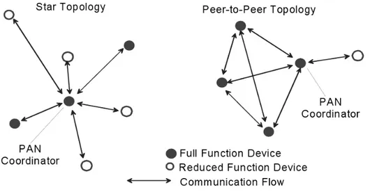
According to the application requirements, a network may be organized in either two topologies: star topology and peer-to-peer topology (Figure 2.1). The star topology mirrors the classic host-client network paradigm: all the messages from devices must pass through the single central controller, called the PAN coordinator; every device has to associate with the PAN coordinator to be part of the network. Also in peer-to-peer topologies there is a PAN coordinator, but any device is allowed to communicate with any other device (as long as they are in range of one another) creating a mesh network if they are supposed to do so.
The physical medium is accessed through a Carrier Sense Multiple Access
2.1. Overview 13
Figure 2.1: Star and peer-to-peer topology examples
protocol, with Collision Avoidance (CSMA/CA). It can be used for channel access either in an un-slotted version or in a time-slotted version with beacon frames to keep motes synchronized. In time-slotted version, between every two beacons, each device competes with others during the Contention Access Period (CAP), while guaranteed time slots can be assigned during the Contention Free Period (CFP).
Common data transmissions use unallocated slots when beaconing is in use; confirmations do not follow the same process. Acknowledgement messages may be optional under certain circumstances, in this case a success assumption is made. Whatever the case, if a device is unable to process a frame at a given time, it simply does not confirm its reception: timeout-based retransmissions can be performed a number of times, following after that a decision of whether to abort or to keep trying.
IEEE 802.15.4 specifies both PHY and MAC layer. The PHY layer acti-vates and deactiacti-vates the radio transceiver, monitors energy detection and link quality indicator for received packets, controls the Clear Channel Assessment (CCA) for CSMA/CA and selects channel frequency and data transmission and reception.
The MAC layer allows the transmission of the MAC frames through the physical channel. It also offers beacon management, channel access,
guaran-2.2. MAC frame structure 14
teed time slot management, frame validation, acknowledged frame delivery, association and disassociation. In addition, the MAC sublayer provides hooks for implementing application-appropriated security mechanisms. [6]
2.2
MAC frame structure
According to the IEEE 802.15.4 standard [9], trasmissions are organized into frames, which have been designed trying to keep complexity at a minimum. The standard, while still assuring robustness for transmissions on a noisy channel, provides four different frame structures that have specific functions:
• Data;
• Acknowledgment; • Beacon;
• MAC Command.
Beacon frames are transmitted by a coordinator to implement significant power saving modes or when attempting to establish a network, Data frames and Acknowledgment frames are used for data transfers and to confirm suc-cessful frame reception respectively. Finally, MAC command frames are used to handle all MAC peer entity control transfers, sending low-level commands from one node to another. Each further protocol layer is added to the structure with layer-specific headers and footers.
2.2.1 Data frame structure
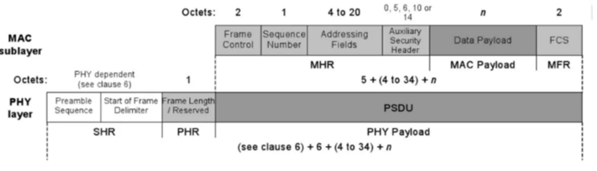
The data frame structure is similar to the other three frame types, its con-tent is originated by the upper layers. The MAC payload is prefixed with the MAC Header (MHR) and appended with the MAC Footer (MFR). The MHR contains a two octets Frame Control Field, a single octet Data Sequence Num-ber (DSN), Addressing Fields whose size changes according to the addressing mode, and, optionally, a variable-length Auxiliary Security Header (ASH).
The MFR is composed of a 16-bit Frame Check Sequence (FCS). The MHR, the MAC payload, and the MFR together form the MAC data frame (Figure
2.3. MAC header and auxiliary security header 15
Figure 2.2: Data Frame and PHY Packet
2.2). These fields compose the PHY payload. The PHY packet is completed by the Synchronization Header (SHR) and the PHY header (PHR). The SHR contains a preamble sequence to allow the receiver to acquire and synchronize the incoming signal and a start of frame delimiter that signals the end of the preamble. Besides, the PHR carries the frame length byte, which indicates the length of the PHY payload.
2.3
MAC header and auxiliary security header
Figure 2.3: MAC Frame
The MAC frame is composed of the MAC header, the MAC payload, and the MAC Footer. However, some fields like the addressing fields or the security header might not be included in all frames, so it has a variable length, as shown in Figure 2.3.
2.3. MAC header and auxiliary security header 16
Figure 2.4: Frame Control Field
2.3.1 Frame control field
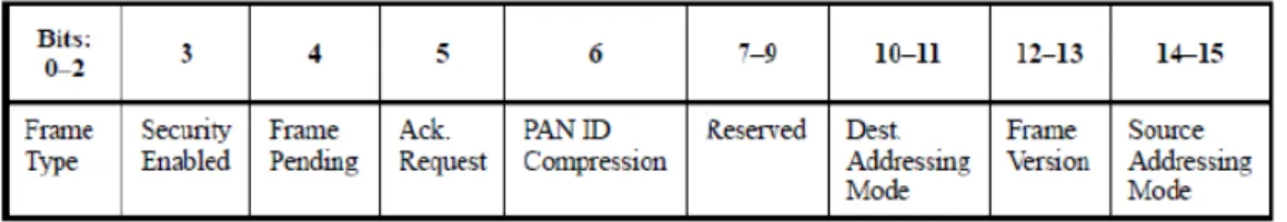
The Frame Control Field is a two octets field. It contains information defining the frame type, addressing fields type, and other control flags. It is formatted as illustrated in Figure 2.4.
2.3.1.1 Frame type subfield
The Frame Type subfield contains the 3-bit encoding of the current frame type (command, beacon, acknowledgment or data).
2.3.1.2 Security enabled subfield
The Security Enabled subfield is set to one if the frame is protected by the MAC security sublayer and must be set to zero otherwise. The Auxiliary Security Header field of the MHR is present only if this subfield is set to one.
2.3.1.3 Frame pending subfield
The Frame Pending subfield is set to one if the device sending the frame has more data for the recipient. It is used only in beacon frames or frames trans-mitted either during the CAP by devices operating on a beacon-enabled PAN or at any time by devices operating on a nonbeacon-enabled PAN. Otherwise, it shall be set to zero on transmission and ignored on reception.
2.3.1.4 Acknowledgment subfield
The Acknowledgment Request subfield is one bit in length and specifies whether an acknowledgment is required from the recipient device when receiving a data
2.3. MAC header and auxiliary security header 17
or MAC command frame. If this subfield is set to one, the recipient device sends an acknowledgment frame only if, on reception, the frame passes the third level of filtering. If this subfield is set to zero, the recipient device will never send acknowledgment frames.
2.3.1.5 PAN ID compression subfield
The PAN ID Compression subfield specifies whether the MAC frame to be sent contains only one of the PAN identifier fields when both source and destination addresses are present. If this subfield is set to one and both the source and destination addresses are present, the frame has to contain only the Destination PAN Identifier field, and the Source PAN Identifier field is assumed to be equal to the destination’s.
2.3.1.6 Frame version subfield
The Frame Version subfield specifies the 2-bit encoding of the frame version.
2.3.1.7 Addressing mode subfields
Finally, the Destination Addressing Mode and the Source Addressing Mode subfields indicate if address fields contain 16-bit short addresses or 64-bit ex-tended addresses.
2.3.2 Auxiliary security header
Figure 2.5: Auxiliary Security Header
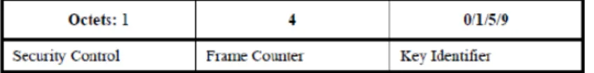
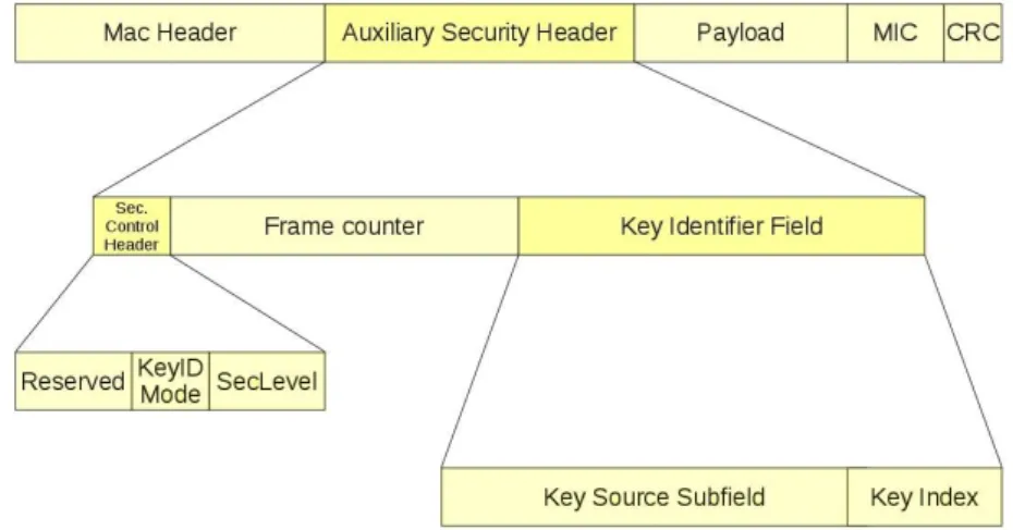
The Auxiliary Security Header has a variable length and, as shown in Fig-ure 2.5, it contains information required for security processing, including the Security Control Field, the Frame Counter Field, and the Key Identifier Field. It is present only if the Security Enabled subfield of the Frame Control field is set to one. It is formatted as illustrated in Figure 2.6.
2.3. MAC header and auxiliary security header 18
Figure 2.6: Auxiliary Security Header Structure 2.3.2.1 Security control subfield
Figure 2.7: Security Control Subfield
The 8-bit Security Control field is used to provide information about what kind of protection is applied to the frame. The Security Control Field has to be formatted as shown in Figure 2.7.
The Security Level subfield is three bit in length and indicates the actual frame protection provided. This value can be adapted on a frame-by-frame basis and allows for varying levels of data authenticity (to allow minimization of security overhead in transmitted frames where required) and for optional data confidentiality. Table 2.1 summarizes all security levels available.
The Key Identifier Mode subfield is two bit in length and indicates whether the key used to protect the frame can be derived implicitly or explicitly. Fur-thermore, it is used to indicate the particular representation of the Key Iden-tifier field, if the key is derived explicitly. The Key IdenIden-tifier Mode subfield is set according to Table 2.2. The Key Identifier field of the Auxiliary Security Header is present only if this subfield has a value not equal to 0x00.
2.3. MAC header and auxiliary security header 19
Security Level Security Control Security Data Data Identifier Field Attributes confidentiality authenticity
0x00 ’000’ None OFF NO (M = 0)
0x01 ’001’ MIC-32 OFF YES (M = 4) 0x02 ’010’ MIC-64 OFF YES (M = 8) 0x03 ’011’ MIC-128 OFF YES (M = 16)
0x04 ’100’ ENC ON NO (M =0)
0x05 ’011’ ENC-MIC-32 ON YES (M = 4) 0x06 ’110’ ENC-MIC-64 ON YES (M = 8) 0x07 ’111’ ENC-MIC-128 ON YES (M = 16)
Table 2.1: Security Level values and options
Key Identifier Security Description
Key Identifier mode Mode subfield
field length (octets) 0x00 ’00’
Key is determined implicitly from the
0 originator and receipient(s) of the frame
as indicated in the frame header.
0x01 ’01’
Key is determined from the 1-octet Key
1 Index subfield of the Key Identifier Field
of the auxiliary security header in conjunction with macDefaultKeySource.
0x02 ’10’
Key is determined explicitly from the
5 4-octet Key Source subfield and the
1-octet Key Index subfield of the Key Identifier Field of the auxiliary security
header
0x03 ’11’
Key is determined explicitly from the
9 8-octet Key Source subfield and the
1-octet Key Index subfield of the Key Identifier Field of the auxiliary security
header.
2.4. Security structures 20
2.3.2.2 Frame counter field
The Frame Counter field is a 4-octets field representing the macFrameCounter attribute of the originator of a protected frame. It is used to assure replay protection.
2.3.2.3 Key identifier field
Figure 2.8: Key Identifier Field
The Key Identifier field has variable length and is used for cryptographic protection of outgoing frames, either explicitly or in conjunction with implicitly defined side information. The Key Identifier field is present only if the Key Identifier Mode subfield of the Security Control field of the Auxiliary Security Header is set to a value different from 0x00. The Key Identifier field is formatted as illustrated in Figure 2.8.
The Key Source subfield, if present, is either four octets or sixteen octets in length, according to the value specified by the Key Identifier Mode subfield of the Security Control field, and indicates the originator of a group key. The Key Index subfield is one octet in length and allows unique identification of different keys having the same originator.
2.4
Security structures
The MAC sublayer is responsible for providing security services on specified incoming and outgoing frames, when requested by the higher layers. The in-formation according to which is determined how to provide security is located in the security-related PIB (PAN Information Base) [9]. This security-related PIB is divided in seven structures:
2.4. Security structures 21
• Device Table;
• Minimum security level table; • Frame counter;
• Automatic request attributes; • Default key source;
• PAN coordinator address.
The Key table contains descriptors, which are keys with related key-specific information required for security processing.
The device table holds device-descriptors, containing device-specific address-ing and security-related information which, combined with key-specific infor-mation from the key table, provide all the keying material needed to secure/un-secure frames.
The minimum security level table holds information regarding the mini-mum security level the device expects having applied by the originator of a frame, depending on frame type and, if it concerns a MAC command frame, the command frame identifier.
The four octets frame counter is used to provide replay protection and se-mantic security of the cryptographic building block used for securing outgoing frames. Such counter is an integer which is incremented every time an outgo-ing frame is secured. When the frame counter reaches its maximum value of 0xffffffff, the associated keying material can no longer be used, thus requiring all keys to be updated.
The Automatic Request table holds all the information needed to secure outgoing frames generated automatically and not as a result of a higher layer primitive, as is the case with automatic data requests.
The default key source is commonly shared between originator and recipi-ent(s) of a secured frame, so that, when combined with additional information explicitly contained in the requesting primitive or in the received frame, it al-lows an originator or a recipient to determine the key required for securing or unsecuring the frame, respectively. The address of the PAN coordinator is an information commonly shared between all devices in a PAN. The code of the implementation can be seen in Appendix A.
2.5. Security modes 22
2.5
Security modes
The 802.15.4 security layer is handled at the MAC layer, below application control. The application specifies its security requirements by setting the ap-propriate control parameters into the radio stack. If an application does not set any parameters, then security is not enabled by default. An application must explicitly enable security.
The specification does not support security for acknowledgement packets; other packet types can optionally support integrity protection and confiden-tiality protection. An application has a choice of security suites that control the type of security protection that is provided for the transmitted data. Each security suite offers a different set of security properties and guarantees, and ultimately different packet formats.
The 802.15.4 specification defines eight different security suites. We can broadly classify them by the properties they offer: no security (NO SEC), en-cryption only (CTR), authentication only (CBC MAC), and both enen-cryption and authentication (CCM). Each category that supports authentication comes in three variants depending on the size of the MIC it offers. Each variant is considered a different security suite and has its own name. In fact, the Mes-sage Integrity Code (MIC) can be either four, eight, or sixteen bytes long. The longer the MIC is, the lower is the chance an adversary has to blind forgery by guessing an appropriate code.
An application indicates the chosen security suite in the MAC frame header. 802.15.4 radio chips control what security suite and keying information to use. The security material is the persistent state necessary to execute the security suite. The application must specify a boolean indicating whether security is enabled. If no security is requested, the packet is sent out as is.
On packet reception, the MAC layer consults the packet flags field in order to determine if any security suite has been applied to that packet. If no security is used, the packet is passed as is to the application. Otherwise, the appropri-ate security suite, such as key and replay counter, is applied to the incoming packet, presenting the application with an error message if the procedure fails somewhat. In the following sections will be provided more details about the above-mentioned security suites.
2.5. Security modes 23
2.5.1 NO SEC
This is the simplest security suite. Its inclusion is mandatory in all radio chips. It does not manage any security material and it does not provide any security guarantees.
2.5.2 CTR
Figure 2.9: CTR Frame Format
This suite provides confidentiality protection using the AES block cipher with counter mode. To encrypt data under counter mode, the sender breaks the cleartext packet into 16-byte blocks and computes ci = pi⊕ Ek(xi). Each
16-byte block uses its own varying counter, which we call x1. The recipient
recovers the original plaintext by computing pi = ci ⊕ Ek(xi). Clearly, the
recipient needs the counter value x1 in order to reconstruct pi .
The x1 counter, known as a nonce, is composed of a static flags field, the
senders address, and three separate counters: a 4-byte frame counter that iden-tifies the packet, a 1-byte key counter field, and a 2-byte block counter that numbers the 16-byte blocks within the packet. The sender increments the frame counter after encrypting each packet. When it reaches its maximum value, the radio returns an error code and the key has to be changed. The requirement is that the nonce must never repeat within the lifetime of any single key, and the role of the frame and key counters is to prevent nonce reuse. The block counter ensures that each block will use a different nonce value; the sender does not need to include it within the packet, since the receiver can infer its value for each block.
As shown in Figure 2.9, the sender includes in the packet three main com-ponents: the frame counter, key counter, and encrypted payload into the data payload field of the packet.
2.5. Security modes 24
2.5.3 CBC MAC
Figure 2.10: CBC MAC Frame Format
This suite provides integrity protection using CBC MAC. The sender can compute either a four, eight, or sixteen bytes Message Integrity Code (MIC) using the CBC MAC algorithm, leading to three different variants. The MIC can only be computed by parties with the symmetric key and can protect packet headers as well as the data payload. The sender appends the plaintext data with the MIC.
The recipient verifies the MAC by computing the MAC and comparing it with the value included in the packet, deciding wether the packet is authenti-cated or not. Figure 2.10 shows the format of this packet.
2.5.4 CCM
Figure 2.11: CCM Frame Format
This security suite uses CCM mode for both encryption and authentication. Broadly, it first applies integrity protection over the header and data payload using CBC MAC and then encrypts both the data payload and the MIC using CTR. So CCM combines the fields from both the authentication and encryption
2.6. Key identifier modes 25
operations such as the MIC and the frame counter. These fields serve the same function as above. As CBC MAC, also CCM has three variants depending on the MIC size. Figure 2.11 shows the format of this packet.
2.6
Key identifier modes
The Key Identifier Mode subfield is two bits in length and indicates whether the key used in order to protect the frame can be derived implicitly or explicitly. Furthermore, it is used to indicate the particular representations of the Key Identifier field if it si derived explicitly. The Key Identifier Mode subfield shall be set to one of the values listed in the following sections. This field specifies the mode used in order to identify and retrieve the key used by the originator of the received frame. This parameter is ignored if the SecurityLevel parameter is set to 0x00.
There are four different modes: KeyIdMode0, KeyIdMode1, KeyIdMode2 and KeyIdMode3. The increment of the index corresponds to an enhancement of their peculiarities, but also of their complexity. The KeyIdMode0 just allows two or more nodes to send or receive data secured with a static, uniform, sin-gle key. The KeyIdMode1 provides more keys, selected from a sinsin-gle KeyTable thanks to the KeyIndex subfield of the Auxiliary Security Header. The keyTable is located at the default index written in the MacDefaultKeySource field of the PIB structure. This mode allows a key change just changing the index of the default key table. The two modes left are the most complex and com-plete. The KeyIdMode2 and KeyIdMode3 provide, besides the KeyIndex, also a KeySourceAddress which locates a different KeyTable filled with some differ-ent KeyDescriptors. So distinct devices are allowed to secure data using keys provided by different sources.
2.6.1 KeyIdMode0
2.6. Key identifier modes 26
The key is determined implicitly from the originator and receipient(s) of the frame, as indicated by the frame header whose structure is shown in Figure 2.12.
2.6.2 KeyIdMode1
Figure 2.13: KeyIdMode1 Security Subheader Format
The key is determined from the 1-octet Key Index subfield of the Key Iden-tifier field of the auxiliary security header in conjunction with macDefault-KeySource. The structure of the Auxialiary Security Header for this KeyId-Mode is shown in Figure 2.13.
2.6.3 KeyIdMode2
Figure 2.14: KeyIdMode2 Security Subheader Format
The key is determined explicitly from the 4-octet Key Source subfield and the 1-octet Key Index subfield of the Key Identifier field. The structure of the Auxialiary Security Header for this KeyIdMode is shown in Figure 2.14.
2.6.4 KeyIdMode3
Figure 2.15: KeyIdMode3 Security Subheader Format
2.6. Key identifier modes 27
the 1-octet Key Index subfield of the Key Identifier field. The structure of the Auxialiary Security Header for this KeyIdMode is shown in Figure 2.15.
Chapter 3
Tmote sky and CC2420
3.1
Tmote sky
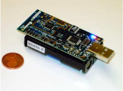
Figure 3.1: A simple Tmote Sky mote
A sensor node, also known as a ’mote’, is a node used in a wireless sensor network. It can perform various kind of processing: it can monitor applications, it can gather sensory information and it can set up network connections with other motes forming a network. As can be seen in Figure 3.1, one point of strength about motes is their small dimension, combined with industry
3.1. Tmote sky 29
dards like USB, so providing flexible interconnection with peripherals [5].
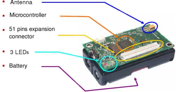
Figure 3.2: Components of a Tmote Sky mote
In the Figure 3.2, we can see the components of the mote: an antenna, to send and receive data; a microcontroller to perform tasks, process data and control the functionality of other components in the sensor node; three leds, useful to signal certain events or for debugging and an AA battery slot. A generic sensor has five subsystems (Figure 3.1), each one with a specific task:
• Sensing subsystem; • Processing subsystem; • Communication subsystem; • Actuation subsystem;
• Power management subsystem.
The sensing subsystem is designed to get information about the environment used by other subsystems. The processing subsystem is designated to take data from the sensing subsystem and to elaborate them so making it possible they can be used by others. The communication subsystem sends and receives packets. The power management subsystem concerns all the operations about
3.2. CC2420 chipset 30
Figure 3.3: Functional blocks of a generic mote
battery managing (e.g. power saving). Finally, the actuation subsystem gets information from sensing and processing and decides how to control and make the system evolve.
The motes used developing this thesis are Tmote sky: it is an open source platform designed to enable cutting-edge experimentation for the research com-munity. As [5] explains, the key Features of this suite are:
• IEEE 802.15.4/ZigBee compliant RF transceiver;; • Interoperability with other IEEE 802.15.4 devices; • 8MHz CC2420 microcontroller (10k RAM, 48k Flash); • Integrated onboard antenna;
• Low current consumption;
• Programming and data collection via USB; • Runs TinyOS 1.1.10 or higher.
3.2
CC2420 chipset
CC2420 is the chipset Tmote sky motes use. It provides hardware support for the cryptographic primitives and is used in several applications: Zigbee
3.2. CC2420 chipset 31
and TinyOS systems, home and building automation, industrial control and wireless sensor networks.
The CC2420 is a single-chip 2.4 GHz IEEE 802.15.4 compliant transceiver designed for low power and low voltage wireless applications. It provides exten-sive hardware support for packet handling, data buffering, burst transmissions, data encryption, data authentication, clear channel assessment, link quality indication and packet timing information. Between its many features, we can highlight the separate transmit and receive FIFOs, the IEEE 802.15.4 MAC hardware support (CRC 16 computation, Energy Detection, Link Quality de-tection, etc.) and IEEE 802.15.4 MAC hardware security (CTR encryption/de-cryption, CBC MAC authentication CCM encryption/decryption and authen-tication, stand-alone AES encryption) [1].
3.2.1 Configuration and Data Interface
There are thirty-three 16-bit configuration and status registers, fifteen com-mand strobe registers, and two 8-bit registers to access the separate transmit and receive FIFOs. Each data register is addressed by a 6-bit address. In each register read or write cycle, twenty-fours bits are read. Also the configuration registers can be read by the microcontroller.
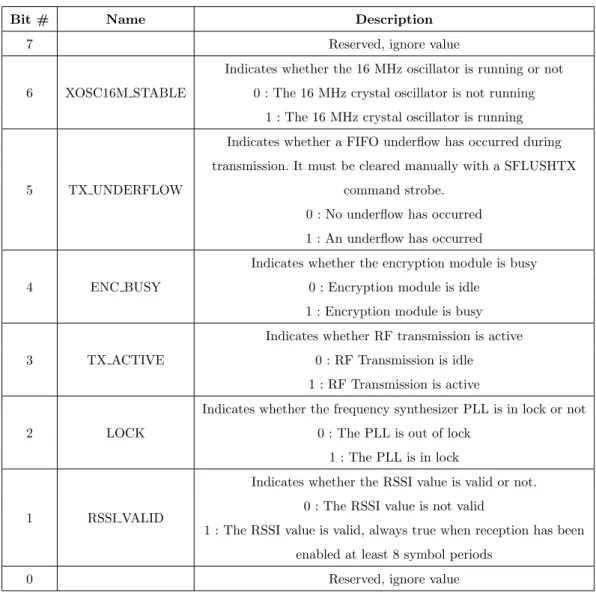
CC2420 then returns the data from the addressed register in sixteen clock cycles. After the transfer, the CC2420 status byte is returned on the SO pin. The status byte contains 6 status bit whose configuration is described in Table 3.1. A SNOP (no operation) command strobe may be used to read the status byte.
Command strobes may be viewed as single byte instruction to CC2420. These commands must be used to enable receive mode, start decryption etc. All command strobes can be viewed in Table 3.2.
3.2.2 RAM access
CC240 also has 368 bytes RAM that can be accessed through the SPI interface. These registers contain a one-to -one mapping of the FIFO registers, the KEY0 and the KEY1 registers, the RXNONCE and the TXNONCE registers. This
3.2. CC2420 chipset 32
Bit # Name Description 7 Reserved, ignore value 6 XOSC16M STABLE
Indicates whether the 16 MHz oscillator is running or not 0 : The 16 MHz crystal oscillator is not running
1 : The 16 MHz crystal oscillator is running
5 TX UNDERFLOW
Indicates whether a FIFO underflow has occurred during transmission. It must be cleared manually with a SFLUSHTX
command strobe. 0 : No underflow has occurred 1 : An underflow has occurred 4 ENC BUSY
Indicates whether the encryption module is busy 0 : Encryption module is idle
1 : Encryption module is busy 3 TX ACTIVE
Indicates whether RF transmission is active 0 : RF Transmission is idle 1 : RF Transmission is active 2 LOCK
Indicates whether the frequency synthesizer PLL is in lock or not 0 : The PLL is out of lock
1 : The PLL is in lock
1 RSSI VALID
Indicates whether the RSSI value is valid or not. 0 : The RSSI value is not valid
1 : The RSSI value is valid, always true when reception has been enabled at least 8 symbol periods
0 Reserved, ignore value
3.2. CC2420 chipset 33
Address Register Description
0x00 SNOP No Operation (has no other effect than reading out status-bits) 0x01 SXOSCON Turn on the crystal oscillator (set XOSC16M PD = 0 and
BIAS PD = 0)
0x02 STXCAL Enable and calibrate frequency synthesizer for TX. Go from RX/TX to a wait state where only the synthesizer is running.
0x03 SRXON Enable RX
0x04 STXON Enable TX after calibration (if not already performed) Start TX in-line encryption if SPI SEC MODE = 0 0x05 STXONCCA If CCA indicates a clear channel:Enable calibration, then TX.
Start in-line encryption if SPI SEC MODE = 0, else do nothing. 0x06 SRFOFF Disable RX/TX and frequency synthesizer
0x07 SXOSCOFF Turn off the crystal oscillator and RF
0x08 SFLUSHRX
Flush the RX FIFO buffer and reset the demodulator. Always read at least one byte from the RXFIFO before issuing the
SFLUSHRX command strobe 0x09 SFLUSHRX Flush the TX FIFO buffer
0x0A SACK Send acknowledge frame, with pending field cleared 0x0B SACKPEND Send acknowledge frame, with pending field set 0x0C SRXDEC Start RXFIFO in-line decryption/authentication (as set by
SPI SEC MODE)
0x0D STXENC Start TXFIFO in-line encryption/authentication (as set by SPI SEC MODE), without starting TX
0x0E SAES
AES Stand alone encryption strobe. SPI SEC MODE is not required to be 0, but the encryption module must be idle. If not,
the strobe is ignored
3.2. CC2420 chipset 34
mapping is very useful to make debugging, in fact the TXFIFO is write only, but it may be read back using RAM access.
Data are read and written one byte at a time, as with RAM access. The RXFIFO is both writeable and readable. KEY0 and KEY1 registers contain a 16-bit key used for ciphering/deciphering operation. After a key is writ-ten in any of these registers, it is selected and then used when reading the SEC TXKEYSEL/SEC RXKEYSEL bit in SECCTRL0 register. TXNONCE and RXNONCE contain nonce.
3.2.3 Security operations
CC2420 features hardware IEEE 802.15.4 MAC security operations. This in-cludes counter mode (CTR) encryption/decryption, CBC MAC authentication and CCM encryption and authentication. All security operations are based on AES encryption using 128 bit keys and they are performed within the transmit and receive FIFOs on a per-frame basis.
The SAES, STXENC and SRXDEC command strobes are used to start security operations in CC2420 as will be described in the following sections. The ENC BUSY status bit may be used to monitor when a security operation has been completed. Security command strobes issued while the security engine is busy, will be ignored and the ongoing operation will be completed. The CC2420 RAM space has storage space for two individual keys (KEY0 and KEY1).
Transmit, receive and stand-alone encryption may select one of these two keys relying on the three control bits SEC TXKEYSEL, SEC RXKEYSEL and SEC SAKEYSEL in the SECCTRL0 register. A way of establishing the keys used for encryption and authentication must be decided considering the particular application requirements. IEEE 802.15.4, in fact, does not define how this is done, it is left to the higher layers of the protocol. However, the nonce must be correctly initialized before starting any reception or transmission [7].
The in-line security mode is set in SECCTRL0.SEC MODE to one of the following modes:
• NO SEC (disabled);
3.2. CC2420 chipset 35
• CTR (encryption/decryption);
• CCM (authentication and encryption/decryption).
When enabled, transmission (TX) in-line security is started in two differ-ent ways: the first one is issuing the STXENC command strobe, so in-line security will be performed within the TXFIFO buffer, but a transmission will not be started. The second one is issuing the STXON or STXONCCA com-mand strobe, so in-line security will be performed within the TXFIFO and a transmission of the ciphertext is started.
When enabled, reception (RX) in-line security is started issuing a SRXDEC command strobe, so the first frame in the RXFIFO buffer is decrypted/au-thenticated as set by the current security mode. RX in-line security operations are always performed on the first frame currently inside the RXFIFO, even if parts of this has already been read out over the Serial Peripheral Interface (SPI). This allows the receiver to first read the source address out, making it possible to decide which key to use before doing authentication of the com-plete frame. In CTR or CCM mode it is of course important that bytes to be decrypted are not read out before the security operation is started.
3.2.3.1 CTR mode encryption/decryption
CTR mode encryption/decryption is performed by CC2420 on MAC frames within the TXFIFO/RXFIFO respectively. SECCTRL1.SEC TXL/SEC RXL flags in this control register set the number of bytes between the length field and the first byte to be encrypted/decrypted respectively, so controlling the number of plaintext bytes in the current frame.
When encryption is initiated, the plaintext in the TXFIFO is then en-crypted. The encryption module will encrypt all the plaintext currently avail-able or it will wait if not everything is prebuffered. The encryption operation may also be started without any data in the TXFIFO at all, and data will be encrypted as soon as they are written to the TXFIFO. When decryption is initiated issuing the SRXDEC command strobe, the ciphertext of the RXFIFO is then decrypted.
3.2. CC2420 chipset 36
3.2.3.2 CBC MAC
CBC MAC in-line authentication is provided by CC2420 hardware. When en-abling CBC MAC in-line TXFIFO authentication, the generated MIC is writ-ten to the TXFIFO for transmission. The frame length must include the MIC. SECCTRL1.SEC TXL/SEC RXL flags in this control register set the num-ber of bytes between the length field and the first byte to be authenticated. Normally it is set to 0 for MAC authentication. SECCTRL0.SEC M flag in this control register set the MIC length M, encoded as (M − 2)/2. SECC-TRL0.SEC CBC HEAD flag defines if the authentication length is used as the first byte of data to be authenticated or not. This bit should be set to one.
When enabling CBC-MAC in-line RXFIFO authentication, the generated MIC is compared to the MIC in the RXFIFO. The last byte of the MIC is replaced in the RXFIFO with 0x00 if MIC is correct or 0xFF if MIC is incorrect.
3.2.3.3 CCM
CCM combines CTR mode encryption and CBC MAC authentication in a single operation. SECCTRL0.SEC M flag sets the MIC length M, encoded as (M − 2)/2. SECCTRL0.SEC CBC HEAD flag defines if the authentication length is used as the first byte of data to be authenticated or not. This bit should be set to one. SECCTRL1.SEC TXL/SEC RXL sets the number of bytes after the length field to be authenticated but not encrypted. The MIC is generated and verified in the same way descibed in the CBC-MAC subsection.
3.2.3.4 Nonce structure
The receive and transmit nonces used for encryption and decryption are lo-cated in RAM, starting from addresses 0x110 and 0x140 respectively. They are both sixteen bytes. The nonce must be correctly initialized before receiving or transmitting secured frames. The format of the nonce is shown in Figure 3.4.
The standard imposes the block counter to be set to one, the key sequence counter is controlled by a layer above the MAC layer. The frame counter must be increased at each new frame by the MAC layer. The source address is the 64-bit IEEE address.
3.2. CC2420 chipset 37
Figure 3.4: IEEE 802.15.4 Nonce
CC2420 gives the user full flexibility in selecting the flags for nonces accord-ing to the chosen security level. The flag settaccord-ing is stored in the most significant byte of the nonce. The flag byte used for encryption and authentication is then generated as shown in Figure 3.5.
Chapter 4
Security implementation
4.1
Overview
IEEE 802.15.4 offers several ways to secure a frame: packets can be only en-crypted, only authenticated or both encrypted and authenticated. In our sce-nario, we consider some Reduced Function Devices (RFDs) transmitting data with different security levels to the Full Function Device (FFD) coordinator, that decrypts messages and sends back acks. When security is turned off, upper layers does not send to MAC any security parameters: when the frame is built, security routines are not called and the frame is sent in clear.
At the startup of the application, both RFDs and FFD set their security data structures, such as Key Table and Device Table, according to the security parameters they are going to use. Then, while parsing the frames, the coor-dinator understands whether it has security or not and, eventually, recognizes the security level, behaving appropriately
When security is active, the first step consists in verifying consistency be-tween table contents and security parameters. If these checks succeed, the Aux-iliary Security Header is built and inserted into the MAC frame. Finally, the proper security routines are called before sending the frame.
The coordinator, while parsing the frame, understands that it is secured and then proceeds to unsecure it in a coherent manner. It makes the consis-tency checks too, so verifying the correctness of its table contents. If everything works, it recognizes the security level and unsecures the packet relying on the
4.2. Security data structures 39
opportune security routines [10].
The security parameters mentioned before are overviewed by Table 4.1 and will be deeply explained later.
Name Type Range Description
SecurityLevel Integer 0x00-0x07 The security level to be used KeyIdMode Integer 0x00-0x03 The mode used in order to identify
the key to be used
Key Source
Set of 0
As specified by the The originator of the key to be used. 4, or 8
KeyIdMode parameter
It is ignored if the KeyIdMode octets parameter is ignored or set to 0x00.
KeyIndex Integer 0x01-0xff
The index of the key to be used. It is ignored if the KeyIdMode parameter is ignored or set to 0x00
Table 4.1: Security Parameters
This security structure is used by application layer to manage the security parameters when the frame is created. The implementation of the security structure is1: typedef s t r u c t i e e e 1 5 4 s e c u r i t y { u i n t 8 t S e c u r i t y L e v e l ; u i n t 8 t KeyIdMode ; u i n t 8 t KeySource [ 8 ] ; u i n t 8 t KeyIndex ; } i e e e 1 5 4 s e c u r i t y t ;
The following section deeply describes the security data structures imple-mentation and their functionalities.
4.2
Security data structures
The PIB security-related attributes are presented in Table 4.2. Among them, the MacKeyTable and the MacDeviceTable are the most important security
4.2. Security data structures 40
data structure. Mainly, they are a set of KeyDescriptor and DeviceDescriptor respectively.
Attribute Identifier Type Range Description Default
macKey-0x71 List of -A table of Key-(empty) Table KeyDescriptor Descriptors, entries each containing keys and related-security information macKey-0x72 Integer Implementa-The number of 0 Table-tion specific entries in mac-Entries KeyTable macDevice-0x73 List of -A table of De-(empty) Table Device-viceDescriptor Descriptor entries, each entries indicating a remote device with which this
one securely communicates macDevice-0x74 Integer Implementa-The number of 0 Table-tion specific entries in mac-Entries DeviceTable mac 0x75 Table of -A table of Secu-(empty) Security- SecurityLevel rityLevel-LevelTable Descriptor Descriptors, entries holding information about the minimum secu-rity level expected
4.2. Security data structures 41
continued from previous page Attribute Identifier Type Range Description Default
mac 0x76 Integer Implementa-The number of 0 Security-tion specific entries in mac-LevelTable- SecurityLevel Entries Table
macFrame-0x77 Integer 0x00000000- The outgoing 0x00 Counter 0xffffffff frame counter
macAuto
0x78 Integer 0x00-0x07
The security
0x06
Request level used for
Security- automatic
Level data request
macAuto
0x79 Integer 0x00-0x03
KeyIdMode
0x00
Request-used for auto-KeyIdMode matic data request macAuto-0x7a As specified -The originator All 0xff
Request-by the mac- of the key
KeySource
AutoRequest- used for auto-KeyId- matic data
Mode request
macAuto-0x7b Integer 0x01-0xff
The index of
All 0xff
Request- the key used
KeyIndex for automatic
data request macDefault-0x7c Set of 8 octets -The originator All 0xff KeySource of the default key used for KeyIdMode1
macPAN-0x7d
IEEE address An extended 64-bit address
-Coord- 64-bit IEEE of the PAN
Extended- address coordinator
4.2. Security data structures 42
continued from previous page Attribute Identifier Type Range Description Default
Address MacPAN-0x73 Integer 0x0000-0xffff 16-bit address 0x0000 Coord-of the PAN Short-coordinator Address
Table 4.2: MAC security-related PIB
4.2.1 KeyTable
The key table holds KeyDescriptors, particular data structures able to provide key-specific information. These are retrieved thanks to some parameters ex-plicitly contained in the requesting primitive or in the received frame, and are involved in the outgoing frame key retrieval procedure and the incoming frame security material retrieval procedure, as well as the KeyDescriptor lookup pro-cedure. All these procedures will be described starting from Section 4.4. The implementation of this data structure is the following:
typedef s t r u c t i e e e 1 5 4 m a c K e y T a b l e t { i e e e 1 5 4 K e y D e s c r i p t o r t k e y d e s c r i p t o r [ MAX MAC KEY TABLE ENTRIES ] ;
b o o l v a l i d [ MAX MAC KEY TABLE ENTRIES ] ; } i e e e 1 5 4 m a c K e y T a b l e t ;
4.2.1.1 KeyDescriptor structure
The following rapresents the ieee154 KeyDescriptor t nesC implementation:
typedef s t r u c t i e e e 1 5 4 K e y D e s c r i p t o r t { i e e e 1 5 4 L o o k u p D e s c r i p t o r t
4.2. Security data structures 43
u i n t 8 t k e y i d l o o k u p e n t r i e s ; i e e e 1 5 4 K e y D e v i c e D e s c r i p t o r t
k e y d e v i c e l i s [ MAX MAC DEVICE LIST ENTRIES ] ; u i n t 8 t k e y d e v i c e l i s t e n t r i e s ;
i e e e 1 5 4 K e y U s a g e D e s c r i p t o r t
k e y u s a g e l i s t [ MAX MAC KEY USAGE LIST ENTRIES ] ; u i n t 8 t k e y u s a g e l i s t e n t r i e s ;
i e e e 1 5 4 K e y t key [ 1 6 ] ; } i e e e 1 5 4 K e y D e s c r i p t o r t ;
4.2.2 DeviceTable
The device table holds DeviceDescriptors, containing device-specific addressing information that, when combined with key-specific information from the key table, provide all the keying material needed to secure outgoing and unsecure incoming frames. Device-specific information in the device table is identified based on the originator of the frame, as described in the blacklist checking procedure we are going to describe in Section 4.5.3.1. The implementation of this data structure is:
typedef s t r u c t i e e e 1 5 4 m a c D e v i c e T a b l e t {
i e e e 1 5 4 D e v i c e D e s c r i p t o r t d e v i c e d e s c r i p t o r [ MAX SEC TABLE ENTRIES ] ; b o o l v a l i d [ MAX SEC TABLE ENTRIES ] ;
} i e e e 1 5 4 m a c D e v i c e T a b l e t ;
4.2.2.1 DeviceDescriptor structure
The following rapresents the ieee154 DeviceDescriptor t nesC implementation:
typedef s t r u c t i e e e 1 5 4 D e v i c e D e s c r i p t o r t { i e e e 1 5 4 m a c P A N I d t p a n i d ; i e e e 1 5 4 a d d r e s s t a d d r e s s ; i e e e 1 5 4 m a c F r a m e C o u n t e r t f r a m e c o u n t e r ; b o o l exempt ; } i e e e 1 5 4 D e v i c e D e s c r i p t o r t ;
4.2. Security data structures 44
4.2.3 Minimum security level table
The minimum security level table holds information regarding the minimum security level the device expects to have been applied by the originator of a frame, depending on frame type and, if it concerns a MAC command frame, the command frame identifier. Security processing of an incoming frame will fail if the frame is not adequately protected.
4.2.4 Frame counter
The 4-octet frame counter is used to provide replay protection and semantic security of the cryptographic building block used for securing outgoing frames. The frame counter is included in each secured frame and is one of the elements required for the unsecuring operation at the recipient(s).
The frame counter is incremented each time an outgoing frame is secured, as described in the outgoing frame security procedure (Section 4.4). When the frame counter reaches its maximum value of 0xffffffff, the associated keying material is blacklisted, requiring all keys associated with the device to be up-dated. This provides a mechanism for ensuring that the keying material for every frame is unique and, thereby, provides for sequential freshness.
4.2.5 Automatic request attributes
Automatic request attributes hold all the information needed to secure out-going frames generated automatically and not as a result of a higher layer primitive, as is the case with automatic data requests.
4.2.6 Default key source
The default key source is an information commonly shared between originator and receipient(s) of a secured frame, which, when combined with additional information explicitly contained in the requesting primitive or in the received
4.3. Security functional description 45
frame, allows an originator or a recipient to determine the key required for securing or unsecuring this frame, respectively.
This provides a mechanism for significantly reducing the overhead of security information contained in secured frames in particular use cases.
4.2.7 PAN coordinator address
The address of the PAN coordinator is an information commonly shared be-tween all devices in a PAN, which, when combined with additional information explicitly contained in the requesting primitive or in the received frame, allows an originator of a frame directed to the PAN coordinator or a recipient of a frame originating from the PAN coordinator to determine the key and security-related information required for securing or unsecuring this frame.
4.3
Security functional description
Security implementation is optional on a device. When a device does not im-plement security, it shall not provide a mechanism for the MAC sublayer to perform any cryptographic transformation on incoming and outgoing frames nor require any PIB attributes associated with security.
A device that implements security, on the other hand, shall provide a mech-anism for the MAC sublayer to provide cryptographic transformations on in-coming and outgoing frames using information in the PIB attributes associated with security when the macSecurityEnabled attribute is set to TRUE.
If the MAC sublayer is required to transmit a frame or receives an incoming frame, the MAC sublayer shall process the frame as descibed in Figure 4.1 and Figure 4.4, respectively.
4.4. Outgoing frame security procedure 46
4.4
Outgoing frame security procedure
The inputs to this procedure are: • the frame to be secured; • SecurityLevel;
• KeyIdMode; • KeySource; • KeyIndex.
The outputs from this procedure are the status of the procedure and, if it is SUCCESS, the secured frame.
4.4. Outgoing frame security procedure 47
Fist of all, the procedure does some consistency controls and, if everything works, it shall obtain the key using the outgoing frame key retrieval procedure as described in Figure 4.3. In case of failure, the procedure shall return with a status of UNAVAILABLE KEY. Otherwise, it proceeds with the auxiliary security header insertion and the encryption/authentication. Finally, the pro-cedure updates the frame counter to the macFrameCounter attribute. If the frame counter has the value 0xffffffff, the procedure shall return with a status of COUNTER ERROR.
4.4.1 Outgoing frame consistency checks
Figure 4.2 describes the consistency checks we are going to enumerate.
Figure 4.2: Outgoing frame consistency checks
4.4. Outgoing frame security procedure 48
be secured is set to zero, the procedure shall set the security level to zero. If the Security Enabled subfield of the Frame Control field of the frame to be secured is set to one, the procedure shall set the security level to the SecurityLevel parameter. If the resulting security level is zero, the procedure shall return with a status of UNSUPPORTED SECURITY.
If the macSecurityEnabled attribute is set to FALSE and the security level is not equal to zero, the procedure shall return with a status of UNSUP-PORTED SECURITY.
Then, the procedure shall determine whether the frame to be secured fits the maximum length of MAC frames payload: the procedure shall set the size (M) of the Authentication field to zero if the security level is equal to zero and shall determine this value from the security level otherwise. The procedure shall determine the AuxLen, that is the length, in octets, of the auxiliary security header using the KeyIdMode and the security level. If this check fails, the procedure shall return with a status of FRAME TOO LONG.
4.4.2 Outgoing frame key retrieval procedure
The inputs to this procedure are: • the frame to be secured; • SecurityLevel;
• KeyIdMode; • KeySource; • KeyIndex.
The outputs from this procedure are a passed or failed status and, if passed, a key.
If the KeyIdMode parameter is set to KeyIdMode0 (i.e. implicit key iden-tification), the outgoing frame key retrieval procedure shall determine the key
4.4. Outgoing frame security procedure 49
Figure 4.3: Key retrieval procedure schema
lookup data and key lookup size as follows:
• if the short addressing mode is used, the key lookup data shall be set to the 2-octets SourcePANIdentifier field of the frame right-concatenated with the 2-octets macPANCoordShortAddress attribute, in turn right-concatenated with the single octet 0x00. The key lookup size shall be set to five;
• if the extended addressing mode is used, the key lookup data shall be set to the 8-octet macPANCoordExtendedAddress attribute right-concatenated with the single octet 0x00. The key lookup size shall be set to nine; • if the Destination Addressing Mode subfield of the Frame Control field of
the frame is set to 0x02, the key lookup data shall be set to the 2-octet Destination PAN Identifier field of the frame right-concatenated with the 2-octet Destination Address field of the frame and with the single octet 0x00. The key lookup size shall be set to five;
4.4. Outgoing frame security procedure 50
• if the Destination Addressing Mode subfield of the Frame Control field of the frame is set to 0x03, the key lookup data shall be set to the 8-octet Destination Address field of the frame right-concatenated with the single octet 0x00. The key lookup size shall be set to nine.
If the KeyIdMode parameter is set to a value not equal to KeyIdMode0, the procedure shall determine the key lookup data and key lookup size as follows: • if the KeyIdMode parameter is set to KeyIdMode1 (i.e. default key source address), the key lookup data shall be set to the value of the 8-octet macDefaultKeySource attribute right-concatenated with the single octet KeyIndex parameter. The key lookup size shall be set to nine;
• if the KeyIdMode parameter is set to KeyIdMode2 (i.e. short address key source), the key lookup data shall be set to the 4-octet KeySource parameter right-concatenated with the single octet KeyIndex parameter. The key lookup size shall be set to five;
• if the KeyIdMode parameter is set to KeyIdMode3 (i.e. extended address key source), the key lookup data shall be set to the 8-octet KeySource parameter right-concatenated with the single octet KeyIndex parameter. The key lookup size shall be set to nine.
The procedure shall obtain the KeyDescriptor by passing the key lookup data and the key lookup size to the KeyDescriptor lookup procedure.
If that procedure returns with a failed status, this procedure shall also return with a failed status. The MAC sublayer shall set the key to the Key element of the KeyDescriptor. The procedure shall return with a passed status, having obtained the key identifier and the key as well.
4.4.2.1 Key descriptor lookup procedure
The inputs to this procedure are the key lookup data and the key lookup size. The outputs from this procedure are a passed or failed status and, if passed, a
4.5. Incoming frame security procedure 51
KeyDescriptor.
The procedure, for each KeyDescriptor in the macKeyTable attribute and for each KeyIdLookupDescriptor in the KeyIdLookupList of the KeyDescriptor, shall check whether the LookupDataSize element of the KeyIdLookupDescrip-tor indicates the same integer value as the key lookup size and whether the LookupData element of the KeyIdLookupDescriptor is equal to the key lookup data. If both checks pass, the procedure shall return with this (matching) Key-Descriptor and a passed status.
Otherwise, the procedure shall return with a failed status.
4.5
Incoming frame security procedure
The input to this procedure is the frame to be unsecured. The outputs from this procedure are:
• the unsecured frame; • SecurityLevel;
• KeyIdMode; • KeySource; • KeyIndex;
• the status of the procedure.
All outputs of this procedure are assumed to be invalid unless and until explicitly set in this procedure.
It is assumed the PIB attributes associating KeyDescriptors in macKeyTable with a single, unique device or a number of devices will have been established by the next higher layer.
4.5. Incoming frame security procedure 52
Fist of all, the procedure does some consistency controls and, if nothing goes wrong, it moves on doing the incoming security level checking proce-dure. If that fails, the procedure shall set the unsecured frame to be the frame to be unsecured and return with the unsecured frame, the security level, the key identifier mode, the key source, the key index, and a status of IM-PROPER SECURITY LEVEL.
Otherwise, it proceeds with the incoming frame security material retrieval procedure, described in Figure 4.6. It the procedure succedees, it passess the KeyDescriptor, the frame type, and, depending on whether the frame is a MAC command frame, the first octet of the MAC payload (i.e., command frame identifier for a MAC command frame) to the incoming key usage policy checking procedure.
4.5. Incoming frame security procedure 53
If that procedure fails, the procedure shall set the unsecured frame to be the frame to be unsecured and return with the unsecured frame, the security level, the key identifier mode, the key source, the key index, and a status of IMPROPER KE TYPE. It follows another checking phase, described in Figure 4.5.
If everything works, the procedure shall then use the ExtAddress element of the DeviceDescriptor, the frame counter, the security level, and the Key element of the KeyDescriptor to produce the unsecured frame according to the CCM inverse transformation process.
If the security level specifies the use of encryption, the decryption operation shall be applied only to the actual payload field within the MAC payload. If the CCM inverse transformation process fails, the procedure shall return with a status of SECURITY ERROR.
The procedure shall increment the frame counter and set the FrameCounter element of the DeviceDescriptor to the resulting value. If the FrameCounter element is equal to 0xffffffff, the procedure shall set the Blacklisted element of the KeyDeviceDescriptor. The procedure shall return with the unsecured frame, the security level, the key identifier mode, the key source, the key index, and a status of SUCCESS.
4.5.1 Incoming frame consistency checks
Figure 4.5 describes the consistency checks we are going to enumerate. If the Security Enabled subfield of the Frame Control field of the frame to be unse-cured is set to zero, the procedure shall set the security level to zero.
If the Security Enabled subfield of the Frame Control field of the frame to be unsecured is set to one and the Frame Version subfield of the Frame Control field of the frame to be unsecured is set to zero, the procedure shall return with a status of UNSUPPORTED LEGACY.
4.5. Incoming frame security procedure 54
Figure 4.5: Incoming frame consistency checks
to be unsecured is set to one, the procedure shall set the security level and the key identifier mode to the corresponding subfields of the Security Con-trol field of the auxiliary security header of the frame to be unsecured and shall set the key source and key index to the corresponding subfields of the Key Identifier field of the auxiliary security header of the frame to be unse-cured, if present. If the resulting security level is zero, the procedure shall set the unsecured frame to be the frame to be unsecured and return a status of UNSUPPORTED SECURITY.
If the macSecurityEnabled attribute is set to FALSE, the procedure shall set the unsecured frame to be the frame to be unsecured and return with the unsecured frame, the security level, the key identifier mode, the key source, the key index, and a status of SUCCESS if the security level is equal to zero and with a status of UNSUPPORTED SECURITY otherwise.
4.5. Incoming frame security procedure 55
4.5.2 Incoming security level checking procedure
The procedure shall determine whether the frame to be unsecured meets the minimum security level by passing the security level, the frame type, and, depending on whether the frame is a MAC command frame, the first octet of the MAC payload (i.e. command frame identifier for a MAC command frame) to this procedure.
The inputs to this procedure are the incoming security level, the frame type and the command frame identifier. The output from this procedure is a passed, failed, or conditionally passed status.
The incoming security level checking for each SecurityLevelDescriptor in the macSecurityLevelTable attribute:
• If the frame type is not equal to MAC command frame (0x03) and the frame type is equal to the FrameType element of the SecurityLevelDe-scriptor, the procedure shall compare the incoming security level with the SecurityMinimum element of the SecurityLevelDescriptor. If this compar-ison fails, the procedure shall return with a conditionally passed status if the DeviceOverrideSecurityMinimum element of the SecurityLevelDe-scriptor is set to TRUE and the security level is set to zero and with a failed status otherwise;
• if the frame type is equal to MAC command frame (0x03), the frame type is equal to the FrameType element of the SecurityLevelDescriptor, and the command frame identifier is equal to the CommandFrameIdenti-fier element of the SecurityLevelDescriptor, the procedure shall compare the incoming security level with the SecurityMinimum element of the Se-curityLevelDescriptor. If this comparison fails, the procedure shall return with a conditionally passed status if the DeviceOverrideSecurityMinimum element of the SecurityLevelDescriptor is set to TRUE and the security level is set to zero and with a failed status otherwise;
4.5. Incoming frame security procedure 56
• If everything goes right, the procedure shall return with a passed status.
4.5.3 Incoming frame security material retrieval procedure
Figure 4.6: Incoming frame security material retrieval procedure schema
The input to this procedure is the frame to be unsecured. The outputs from this procedure are a passed or failed status and, if passed, a KeyDescriptor, a DeviceDescriptor, and a KeyDeviceDescriptor.
As Figure 4.6 describes, the procedure checks if the Key Identifier Mode subfield of the Security Control field of the auxiliary security header of the frame is set to KeyIdMode0. If so, the procedure shall determine the key lookup data and the key lookup size as follows:
• if the source address mode of the FrameControl field is set to 0x00 and the macPANCoordShortAddress attribute is set to a value in the short ad-dressing mode is used, the key lookup data shall be set to the 2-octet