Corso di Laurea Magistrale in
Ingegneria Energetica
A REDUCED ORDER MODEL FOR PREDICTING THE IMPACT
OF RESIDENCE TIME DISTRIBUTION AND UNMIXEDNESS ON
THERMOCHEMICAL ENERGY CONVERSION SYSTEMS
Thesis supervisors: Dr. Rory F.D. MONAGHAN Prof. Alessio FRASSOLDATI
Thesis by:
Alessandro SINGLITICO Reg. Number 783243
i There are many people I want to thank for my research at NUIG and for the years I spent at POLIMI, I want to express my gratitude to:
Dr. Monaghan, for all the opportunities he gave me, for all the teaching, and for his contagious passion for the research and his incredibly friendly manners.
Eoin Burke, for helping and giving me the technical tips I needed to approach the model, and all the other guys in NUIG, who taught me something and with whom I shared the longest tea breaks.
Prof. Frassoldati, for have been always present, for replying to my pushing emails as quick as he could and for pointing me to the right direction of research.
My family: my mother, my father, my brother and obviously all the others, for supporting me (in every sense) daily in Italy and Ireland, for the immense love and for teaching me the attitude towards the hard working, that has always been the basis.
My longtime friends: Prave, Prone, la Vale, Ema, Lozio, Mike, Simo who have always been an essential part of my daily life and who have made it richer (of beer, bbqs, laughs and priceless moments).
My new friends I had the luck to meet at POLIMI (Paolo Reds, Maggio, Sergio, Fede a.k.a. il Senatore, Hench, Tia) and at NUIG and in Ireland: you all made my work less heavy.
There is a probability, not even low, I forgot someone, I am sorry about that and I am going to thank you personally as soon as we meet.
iii
Acknowledgments ... i
List of figures ...vii
List of tables ... x
Abstract ... xi
Sommario ... xii
Thesis presentation ... xiii
Sintesi in italiano ... xv
Chapter 1 : Energy overview and modelling ... 1
1.1 Energy outlook ... 1
1.1.2 Importance of combustion, partial oxidation, gasification ... 3
1.2 Role of modelling ... 4
Chapter 2 : Energy systems: technology and reactions ... 7
2.1 Gas turbines combustor ... 7
2.1.1 Combustion ... 7
2.1.2 NOx and CO emissions ... 8
2.1.3 Emission controls by combustor design ... 11
2.2 Hydrocarbon Reformer ... 13
2.2.1 Partial oxidation reformer ... 15
2.3 Biomass gasifier ... 16
2.3.1 Fluidized bed gasifier ... 17
iv
3.2 Computational instruments ... 24
3.2.1 Initializations and governing equations of the objects used ... 25
3.3 The network ... 29
3.3.1 First level ... 29
3.3.2 Second level ... 31
3.3.3 Third level ... 32
Chapter 4 : Residence time distribution ... 33
4.1 Assumptions ... 33
4.1.1 Definition ... 33
4.1.2 Residence time distribution for a CSTR ... 34
4.1.3 Segregation model ... 35
4.2 Setting the RTD parameter ... 37
4.2.1 Gaussian distribution ... 38
4.2.2 RTD sub-model ... 38
4.2.3 Integration of the sub-model with the third level of the network 41 Chapter 5 : Unmixedness ... 43
5.1 Assumptions ... 43
5.1.1 Definition ... 43
5.1.2 Existing models ... 44
5.2 Setting the unmixedness parameter... 44
v
Chapter 6 : Gas turbine combustor: results and discussion ... 51
6.1 Uncontrolled single stage ... 51
6.1.1 Effect of inlet temperature and pressure ... 52
6.1.2 Effect of the equivalence ratio ... 54
6.1.3 Effect of residence time ... 57
6.2 Wet controlled single stage ... 58
6.2.1 Effect of steam or water injection ... 58
6.3 Double stage combustor ... 61
6.3.1 Lean-lean staging: effect of residence time proportion ... 62
6.3.2 Rich-lean staging: effect of residence time proportion ... 63
6.4 Impact of RTD and unmixedness ... 64
6.4.1 Effect of RTD on an uncontrolled combustor... 65
6.4.2 Effect of RTD on a wet controlled combustor ... 66
6.4.3 Comparison of the effect of RTD on an uncontrolled and a wet controlled combustor ... 67
6.5 Effect of unmixedness ... 69
6.5.1 Effect of unmixedness on an uncontrolled combustor... 69
6.5.2 Effect of unmixedness on a wet controlled combustor ... 70
6.5.3 Effect of unmixedness on a lean-lean combustor ... 72
6.5.4 Effect of unmixedness on a rich-lean combustor ... 74
Chapter 7 : Thermal partial oxidation: results and discussion ... 77
7.1 Effect of inlet parameters ... 77
vi
7.3 Impact of unmixedness ... 83
7.3.1 Effect on the exiting gas composition ... 83
7.3.2 Effect on the exiting gas temperature ... 84
7.3.3 Effect on H2/CO ratio and methane conversion ... 84
Chapter 8 : Notes on gasification ... 87
8.1 Selection of kinetic mechanisms ... 87
8.2 Software limit ... 93
Chapter 9 : Conclusions ... 95
9.1 Comment to the work ... 95
9.2 Critics on the model ... 96
9.4 Future works ... 97 Appendix A ... 99 Appendix B ...101 List of abbreviations ...103 List of symbols ...103 List of references ...105
vii
Fig.1.1: Investment in global energy supply[5]...1
Fig. 1.2: Cumulative global energy supply investment by type in the New Policies Scenario, 2014-2035[5] ...2
Fig. 1.3: SEAI Ireland fossils and renewable sources forecast 2011-2020[6]. ...3
Fig. 2.1: Representation of a gas turbine combustor [7] ...8
Fig. 2.2: Partial oxidation and autothermal reformer schemes ...15
Fig. 2.3: Scheme of the reactions in a biomass gasifier[10]. ...17
Fig. 2.4: Representation of a bubbling fluidized bed gasifier [10]. ...18
Fig. 2.5: Representation of a circulating fluidized gasifier[10]. ...19
Fig. 3.1: Model representation ...24
Fig. 3.2: Legend of the schematic representation of the code ...30
Fig. 3.3: Code network ...31
Fig. 3.4: Second level code network ...31
Fig. 3.5: Third level code network ...32
Fig. 4.1: Schematic representation of turbulence and different trajectory in a combustor ...33
Fig. 4.2: Schematic representation of the "segregation model" ...36
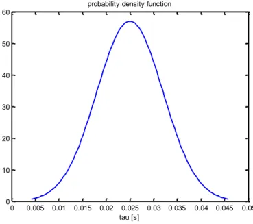
Fig. 4.3: Example of continuous Gaussian distribution for the previous figure (τ=0,25; S=0,3) ...36
Fig. 4.4: residence time distribution computational scheme ...37
Fig. 4.5: Example of a discrete distribution (10 reactors; τ=0,25; S=0,3) ...39
Fig. 4.6: Example of Gaussian distribution (3 reactors; τ=0,25; S=0,3) ...39
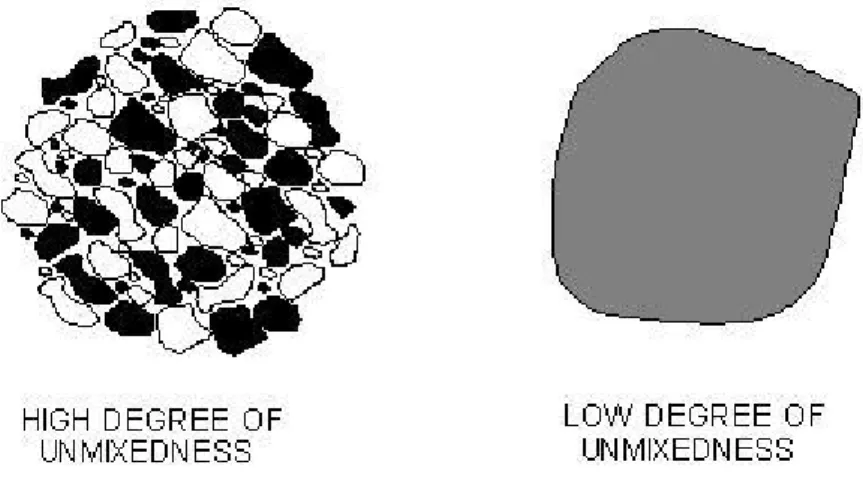
Fig. 4.7: Example of Gaussian distribution (1000 reactors; τ=0,25; S=0,3) .40 Fig. 5.1: Simplified representation of the degree of unmixedness between two fluids ...43
Fig. 5.2: Examples of beta distributions ...45
Fig. 6.1: Impact of inlet temperature on emissions (p= 1atm; φ=0,7; τ=25ms) ...52
viii
Tinlet=450K; τ=25ms) ... 56
Fig. 6.6: Impact of residence time on emissions (p=15atm; Tinlet=450K; φ=0,7) ... 57 Fig. 6.7: Impact of steam/air and water/air ratio on emissions (p=15atm;
Tinlet=450K; Twater,in=300K; φ=0,7; τ=25ms) ... 59
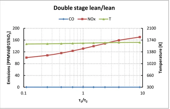
Fig. 6.8: Impact of steam/air and water/air ratio on outlet temperature (p=15atm; Tinlet=450K; Twater,in=300K; φ=0,7; τ=25ms) ... 59 Fig. 6.9: Impact of residence time proportion spent in the two stage on emissions and temperature (p=15atm; Tinlet=450K; φ1=0,7; φ2=0,5;
τ=25ms) ... 63 Fig. 6.10: Impact of residence time proportion spent in the two stage on emissions and temperature (p=15atm; Tinlet=450K; φ1=1,8; φ2=0,4;
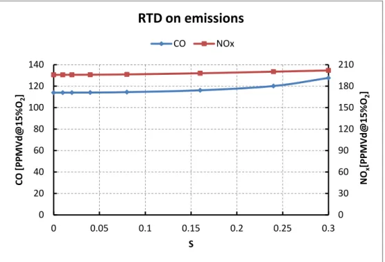
τ=25ms) ... 64 Fig. 6.11: Impact of residence time distribution on emissions on an
uncontrolled combustor (p=15atm; Tinlet=450K; φ=0,7; τ= 25ms) ... 66 Fig. 6.12: Impact of residence time distribution on a wet controlled
combustor (p=15atm; Tinlet=450K; Twate,in=300K; φ=0,7; τ=25ms; ω=0,12 steam) ... 67 Fig. 6.13: Impact of residence time distribution on the slope of CO emissions on an uncontrolled combustor (p=15atm; Tinlet=450K; φ=0,7; τ= 25ms; ω=0,12 steam for the controlled) ... 68 Fig. 6.14: Impact of residence time distribution on the slope of NOx
emissions on an uncontrolled combustor (p=15atm; Tinlet=450K; φ=0,7; τ= 25ms; ω=0,12 steam for the controlled) ... 68 Fig. 6.15: Impact of unmixedness on emissions in an uncontrolled
combustor (p=15atm; Tinlet=450K; φ=0,7; τ=25ms) ... 70 Fig. 6.16: Impact of unmixedness on emissions in a wet controlled
combustor (p=15atm; Tinlet=450K; φ=0,7; τ=25ms; ω=0,12 steam) ... 71 Fig. 6.17: Impact of unmixedness on outlet temperatures (p=15atm;
ix combustor(p=15atm; Tinlet=450K; φ=0,7; τ=25ms, τ1/τ2= 1/9) ...73 Fig. 6.21: Impact of unmixedness on temperatures in a double stage
combustor(p=15atm; Tinlet=450K; φ=0,7; τ= 25ms, τ1/τ2=4) ...74 Fig. 6.22: Impact of unmixedness on emissions in a double stage
combustor(p=15atm; Tinlet=450K; φ=0,7; τ=25ms, τ1/τ2= 4) ...75 Fig. 6.23: Impact of unmixedness on emissions in a double stage
combustor(p=15atm; Tinlet=450K; φ=0,7; τ=25ms; τ1/τ2= 4) ...75 Fig. 7.1: Impact of O2/CH4 ratio on main products molar composition
(p=50atm; Tinlet=1550K) ...78 Fig. 7.2: Impact of residence time on main products molar composition (p=50atm; Tinlet=1550K; O2/CH4=0,7) ...79 Fig. 7.3: Impact of residence time on main products molar composition for two different pressures (Tinlet=1550K; O2/CH4=0,7) ...80 Fig. 7.4: Impact of residence time on H2/CO for three different O2/CH4 (p=50atm; Tinlet=1550K) ...81 Fig. 7.5: Impact of residence time on H2/CO for thee different O2/CH4
(p=50atm; Tinlet=1550K) ...82 Fig. 7.6: Impact of unmixedness on main products molar fractions
(p=50atm; Tinlet=1550K; mean O2/CH4=0,7; τ=1s) ...83 Fig. 7.7: Impact of unmixedness outlet fluid temperature (p=50atm;
Tinlet=1550K; mean O2/CH4=0,7; τ=1s) ...84
Fig. 7.8: Impact of unmixedness on methane conversion and H2/CO ratio (p=50atm; Tinlet=1550K; mean O2/CH4=0,7; τ=1s) ...85 Fig. 8.1: Schemes of biomass gasification reactions[30] ...89 Fig. B.1: Effect of number of CSTRs used in the model on the gas outlet temperature (p=1atm, Tinlet=300K; φ=0,7; τ=25ms) ... 101 Fig. B.2: Effect of number of CSTRs used in the model on the CO emission (p=1atm, Tinlet=300K; φ=0,7; τ=25ms) ... 102 Fig. B.3: Effect of number of CSTRs used in the model on NOx
x
Tab. 2.1: Reactions during reforming processes[9] ... 14 Tab. 8.1: Cellulose reactions [41] (activation energy expressed in
kcal/kmol) ... 90 Tab. 8.2: Lignin reactions [41] (activation energy expressed in kcal/kmol) ... 90 Tab. 8.3: Hemicellulose reactions[41] (activation energy expressed in kcal/kmol) ... 91 Tab. 8.4: Char reactions [43](activation energy expressed in kcal/kmol)... 92
xi Today's primary energy supply is still dominated by the fossil fuels, even if investments on renewable sources are increasing and energy policies are becoming stricter. The aim of this work is to produce a dynamic reduced order model (ROM) flexible and accurate to analyse the impact of a residence time distribution and unmixedness on the most popular thermochemical energy conversion systems: gas turbine combustor, partial oxidation reactor and only with future researches on biomass gasification. This model uses the GRImech3.0 in a Cantera network of CSTRs. The analysis starts with the prediction of the NOx and CO emission behaviour for a gas turbine combustor modifying inlet parameters (temperatures, pressure, residence time, equivalence ratio), then wet and dry emissions controls are simulated. After this first analysis, the impact of a residence time distribution and a grade of unmixedness is studied. Similar analysis has been made on high temperature and pressure partial oxidation where the subject of study has been the efficiency H2/CO and the methane conversion, as in the previous case, modifying the reactants inlet parameters and the distribution residence time and the grade of unmixedness.
A synthetic investigation is given for the case of gasification where the kinetic mechanism and the issues with the software are studied.
The possibility to set-up a large variety of parameters and, consequently, to elaborate a large number of results at near real-time, makes this ROM a powerful tool for the design of a reactor and it suggest the kinetic-optimum conditions for the transformations involved.
Keywords:
reduced order modelling, combustion, unmixedness, residence time, partial oxidation, gasification.xii
L'approvvigionamento di energia primaria odierna è ancora dominato dai combustibili fossili, anche se gli investimenti in materia di fonti rinnovabili sono in aumento e le politiche energetiche stanno diventando sempre più severe. Lo scopo di questo lavoro è quello di creare un modello di ordine ridotto (ROM) flessibile e preciso che analizzi l'impatto della distribuzione del tempo di residenza e del grado di non-miscelamento nei sistemi di conversione termochimica dell'energia più diffusi: ovvero in un bruciatore di una turbina a gas, in un reattore di ossidazione parziale e, dopo futuri sviluppi, in un gassificatore per biomassa. Questo modello utilizza il GRImech3.0 sfruttando una rete di CSTR sul software Cantera. L'analisi inizia con la previsione del comportamento delle emissioni di NOx e CO in un combustore modificando i parametri in ingresso (temperatura, pressione, tempo di residenza, rapporto di equivalenza), dopodiché sono simulate le configurazioni per il controllo delle emissioni (sia wet che dry). Dopo questa prima analisi viene studiato l'impatto di una distribuzione dei tempi di residenza e del grado di non-miscelamento. Allo stesso modo è stata poi effettuata un'analisi nel caso di ossidazione parziale ad alta pressione e temperatura, dove l'oggetto di studio è il parametro H2/CO sul gas prodotto e la conversione del metano. Come nel caso del combustore, si è iniziato modificando i parametri in ingresso, dopodiché è stato studiato l'impatto dellla distribuzione del tempo di residenza e del grado di
non-miscelamento. .
Un'indagine sintetica è stata svolta per il caso della gassificazione, nella quale viene selezionato il meccanismo cinetico integrabile col modello e i problemi derivanti dal limite di Cantera e le possibili soluzioni. La possibilità di configurare una grande varietà di parametri e, conseguentemente, di elaborare un gran numero di risultati quasi in tempo reale, rende questo ROM un flessibile strumento per la progettazione di un reattore, attraverso il quale vengono suggerite le condizioni cinetiche ottimali per le trasformazioni studiate.
Parole chiave:
modello di ordine ridotto, combustione,xiii The goal of this work is to build the basis for a dynamic reduced order model based on kinetic mechanisms able to predict the desired products of an energy system: combustion, partial oxidation and gasification.
In this work is examined the impact of residence time distribution and unmixedness on these processes.
Unmixedness and residence time distribution for combustion have been widely studied for combustion engines, in the case of aero derivative gas turbines [1][2], the literature is poorer on this topic for partial oxidation but we could find several studies on residence times and input conditions that are a good starting point to get more complex results[3][4].
The original aim of the work was to develop a reduced order kinetic-based for the process of gasification of biomass in a fluidized bed, which is flexible to different feedstocks and system operational parameters, considering the large variety and availability of biomass and its potential.
Since the impossibility of Cantera to compute heterogeneous reactions, the creation of the model has started from homogenous reactions, looking forward to develop the software and to study heterogeneous ones. A synthetic resume of the research on biomass gasification, and a possible kinetic mechanism that might be integrated on this model, can be found in the Chapter 8.
In Chapter 1 we could find an energy overview of World and Ireland; the reasons for a kinetic model and a description of the classification of the most used kind of models according the their approach.
In Chapter 2 the state of art of the technologies suitable this model: gas turbine combustors (with some of the methods of emission controls) thermal partial oxidation reactor, and fluidized bed gasifier (this last one for a future development).
Chapters 3, 4, 5 belong to the section Methodology: all the computational methods are explained. Chapter 3 deals with the structure of the model a description of Cantera and the object used and their governing equations, the three levels of the model, Chapter 4 deals with the residence time distribution sub-model, it contains the assumptions, a synthetic literature review and the statistical method. Similar is Chapter 5, it has the same structure of the previous chapter but for the unmixedness sub-model. Chapters 6,7,8 belong to the section Results and Discussion: all the results obtained with the model are presented and explained first for gas turbines
xv Come rivelano i dati dell'ultimo Energy Outlook dell'IEA, seppure le fonti energetiche rinnovabii stanno acquistando importanza a cause delle sempre piuù stringenti politiche energetiche, le fonti fossili sono ancora dominanti nel panorama energetico e i settori upstream di estrazione, trasporto e trasformazione di gas, petrolio e carbone sono destinatari di massicci investimenti.
Da questo dato sorge la necessità di un modello che venga incontro alle necessità di conoscere in maniera semplice, veloce ma accurata i prodotti delle trasformazioni di fonti fossili, come può essere la quantità di idrogeno prodotto in una reazione di ossidazione parziale del metano o delle emissioni di NOx e CO dal combustore di una turbina a gas, e che sia in futuro estendibile anche allo studio di produzione di potenza da fonti rinnovabili, come dalla gassificazione delle biomasse.
In questo lavoro viene studiato l'impatto che ha una distribuzione del tempo di residenza e il grado di non-miscelamento sulle trasformazioni sopracitate.
Nel caso del combustore di una turbina a gas viene studiato il fenomeno della combustione, unica trasformazione all'interno di una turbina a produrre inquinanti, in questo studio ci si è focalizzati sulla produzione di NOx e CO.
I NOx derivano da due fonti: l'azoto presente nell'aria coinvolta nella reazione di combustione (i cosiddetti fuel NOx e Prompt NOx) e l'azoto legato al combustibile (Fuel NOx). I Themal NOx vengono prodotti attraverso il meccanismo spiegato da Zeldovich nelle zone ad alte temperature del combustore, il quale asserisce che la produzione di NOx aumenta esponenzialmente con la temperature e linearmente col tempo di residenza.
Siccome la temperature adiabatica di fiamma dipende anche dal rapporto di equivalenza tra aria e combustibile, da qui la necessità di studiare anche il grado di non-miscelamento dei reagenti.
I Prompt NOx si formano in prossimta del fronte di fiamma come prodotto intermedio della combustione come HCN, N e NH che vanno poi a formare NOx, e si formano sia nel caso di fiamme ricche di combustibile che in fiamme povere di combustibile. La frazione di prompt NOx è decisamente
xvi
zone per controllare il rapporto di equivalenza; o wet controls, che si basano sull'iniezione di acqua o vapore acqueo.
Nel caso di reforming di un idrocarburo viene studiata la produzione effettiva di H2 sull'emissione di CO e la conversione del combustibile. La tecnologia analizzata è quella dell'ossidazione parziale non catalitica che avviene ad alta temperatura e alte pressioni, siccome la reazione di parziale ossidazione è endotermica, per avvenire richiede, nel caso di questo studio, che parte del combustibile venga completamente ossidato, generando potenza termica necessaria a fare avvenire la successiva reazione di parziale ossidazione. In questo caso si hanno rapporti H2:CO che vanno dall' 1:1 al 2:1 senza la necessità di un catalizzatore in reattori come il Fischer-Tropsch.
La reazione di parziale ossidazione di un idrocarburo è soggetta a reazioni simili a quelle che avvengono nel caso di gassificazione di un combustibile solido, e avvengono in tecnologie simili come può essere il reattore Fischer-Tropsch, un gassificatore a letto fluido. Il fatto che invece per la gassificazione reazioni omgenee e eterogenee avvengano parallelamente nello stesso ambiente ne pone dei limiti sostanziali e ne necessità un studio di scambio di massa parallelo ad un'analisi cinetica più complessa per avere delle analisi più accurate. Lo studio di questo processo è stato sospeso a causa dell'impossibilità del software di elaborare reazioni eterogenee, ma una serie di indicazioni, fonti bibliografiche, motivi del problema e possibili soluzioni sono state raccolte sinteticamente nel Capitolo 8.
La creazione di un reduced order model per la previsione dell'impatto che hanno la distribuzione di un tempo di residenza e di un grado di non-miscelamento parte dal presupposto che questi siano due aspetti fisici dell'ambiente turbolento in cui queste reazioni avvengono, in cui i risultati di uno studio di questi processi in un reattore ideale che potrebbe essere un reattore continuo a serbatoio agitato (CSTR) potrebbero di gran lunga allontanarsi da situazioni reali. Per questo per la costruzione del modello si è deciso di partire da unità ideali in parallelo CSTR, articolando una rete a più livelli, in modo da usufruire delle assunzioni che caratterizzano i casi
xvii (combustibile, ossidante, acqua): portate, caratteristiche fisiche (temperatura, pressione, ecc.) e chimiche (composizione).
Altri input sono il grado di non-miscelamento, definito come la deviazione standard normalizzata, ovvero il rapporto tra la deviazione standard e il rapporto di miscelamento medio, che restituisce il valore di quanto il miscelamento reale si allontani dal caso di perfetto miscelamento; assunzione simile per la distribuzione del tempo di residenza che necessità a sua volta di un grado di distribuzione definito come la deviazione standard fratto il tempo di residenza medio. Gli output sono tutte le caratteristiche desiderate del gas prodotto.
L'oggetto principale di Cantera utilizzato nel modello é l'IdealGasReactor, soggetto alle equazioni governanti di un CSTR, ma modificato in modo da sostituire la variabile "volume" con la variabile "tempo di residenza". Da questa modifica viene la possibilità di agire sui tempi di residenza, dalla modifica dei rapporti delle portate in ingresso viene invece la possibilità di agire sui gradi di miscelamento. Detto questo, è possibile separare le portate dei reagenti in ingresso in più flussi di miscele parallele , un numero tale che renda possibile ottenere una distribuzione discreta del grado di non-miscelamento accurata, e allo stesso modo separare lo stesso flusso (conservando il rapporto combustibile/aria) in più CSTR paralleli che processano il fluido con tempi di residenza diversi derivanti a una distribuzione dei tempi di residenza. In questo modo si riesce a ottenere l'effetto di un miscelamento e dei tempi di residenza diversi diversi da quelli ideali. Bisogna fare notare che l'assunzione di indipendenza tra le diverse frazioni di miscele è molto forte.
In questo modo il modello è costruito su più livelli il primo, quello più "superficiale" è caratterizzato da due semplici stadi, in cui è possibile riprodurre situazioni come la separazione del portata di aria in un combustore, il secondo livello consiste nella separazione dei reagenti in più miscele con rapporti diversi, il terzo livello consiste nel processare le singole miscele in CSTRs a tempi di residenza diversi.
Tempi di residenza e rapporti di miscelamento sono raccolti dalle distribuzione di tempi di residenza e del grado di non-miscelamento
xviii
Nel caso del combustore di una turbina a gas sono stati studiati i risultati per le emissioni di NOx e CO nei casi di diversi input iniziali e configurazioni. Casi più semplici rivelano come temperatura e pressione abbiano effetti sulle emissioni: se la temperatura di ingresso aumenta le emissioni aumentano, mentre nel caso di aumento della pressione le emissioni decrescono. Quindi combinando gli effetti nel caso di compressioni isoentropiche notiamo come per i CO l'effetto dominante sia quello della pressione quindi le emissioni di CO decrescono, nel caso contrario l'effetto dominante è quello della temperatura, quindi i NOx aumentano con l'aumentare il rapporto di compressione.
Nel caso di variazioni del rapporto di equivalenza si nota come i CO siano rilevanti in casi di miscele ricche di combustibile e in casi di miscele molto povere di combustibili a causa della mancata ossidazione di CO in CO2. La formazione di NOx è limitata in un range tra 0,5 e 1,5 di equivalence ratio. Il picco di temperatura si ottiene per il valore del rapporto i equivalenza quasi-stechiometrico. Il punto di ottimo è valutato intorno al rapporto di 0,7.
Cambiando il tempo di residenza si nota come dopo l'ignizione i NOx crescono linearmente e CO crolla.
Sono studiati anche gli effetti dell'iniezione di acqua e vapore: il crollo dei NOx è maggiore con la quantità di acqua o vapore iniettata, CO invece crolla solo per un'iniezione limitata dopodiché aumenta, e aumenta maggiormente per l'iniezione di acqua.
Nel caso di controlli dry, separando la portata di aria in due stadi notiamo come nel caso di doppio stadio magro/magro, mantenendo lo stesso tempo di residenza totale per l'intero combustore, il tempo di residenza speso nel primo stadio (che è quello con la temperatura più alta) deve essere di gran lungo inferiore al secondo stadio in cui avviene una semplice diluizione con aria.
Nel caso di doppio stadio ricco/magro si nota come è preferibile fare spendere più tempo nel primo stadio che in cui si ha formazione di NOx
xix combustore incontrollato si ha un aumento delle emissioni solo quando il grado di distribuzione del tempo di residenza è molto alto, ovvero quando parte dei reagenti non si ossidano perchè sfuggono in tempi molto brevi per i NOx e anche perchè la crescita non è perfettamente lineare, più evidente nel caso dei CO poichè nella zona a bassi tempi di residenza post-ignizione i CO sono elevati, quindi allargando la distribuzione in quella zona, le emissioni di CO aumentano.
Similmente per la situazione in cui si ha iniezione di vapore, che pure partendo da quantità inferiori del caso ideale di unico tempo di residenza, le emissioni aumentano più velocemente rispetto alla configurazione non controllata. Nel caso di combustione in due stadi non sono stati notati effetti significativi introducendo una distrubuzione dei tempi di residenza
L'introduzione di un grado di non-miscelamento ha effetti più significativi sulle emissioni, i quali dipendono dal rapporto di equivalenza e dalla portata che reagisce a quel determinato dal rapporto di equivalenza. Nel caso di una combustione al punto di ottimo (rapporto di equivalenza 0,7), si può notare come per CO non ci sia una grossa variazione per bassi valori del grado di non-miscelamento, mentre aumentandolo (ovvero creando zone molto ricche e zone molto magre di combustibile) CO cresce massivamente; nel caso dei NOx si può notare come spostandosi dal punto di ottimo di perfetto miscelamento prima crescano, ovvero raggiungono rapporti di equivalenza in cui i NOx hanno il loro picco, e poi diminuiscano per valori del grado di non-miscelamento più alti. Così similmente per le emissioni di un combustore in cui viene iniettato vapore, con differenze di forma.
Nel caso di combustione doppio stadio magra/magra si nota come il primo stadio sia similare ai precedenti, trattandosi di combustione magra. Nel secondo stadio (diluizione con aria) si nota come i NOx crescano quasi linearmente col grado di non-miscelamento e CO cresca a sua volta con un picco per alti valori del grado di non-miscelamento.
Nel caso di combustione doppio stadio ricca/magra si nota come il primo stadio sia differente dai casi precedenti poichè si parte da una condizione idi perfetto miscelamento con CO alto e NOx quasi nulli e ci si allarga in zone in cui CO é sempre alto e i NOx incominciano a crescere quando la distribuzione si allarga in zone con rapporto di equivalenza inferiore a 1,5.
xx
syngas prodotto, sul rapporto di idrogeno su monossido di carbonio (H2/CO) e sul grado di conversione del metano, con qualche piccola modifica dello stesso codice per potere riconoscere input and output diversi.
E' stata svolta un'analisi sull'impatto che ha il rapporto molare tra ossigeno e metano sulla composizione finale del syngas ed è stato notato come il rapporto ottimo sia lievemente superiore a quello stechiometrico di 0,5. Tale rapporto ottimo è intorno a 0,7 e in cui si ottiene una frazione maggiore di idrogeno prodotto e una conversione quasi totale del metano. Studiando la composizione del syngas per il tempo di residenza si è notato che la reazione ha la sua ignizione a 0,01 ms dopodiché la conversione del metano evolve lentamente fino al suo limite stechiometrico. Ed è stato notato come diminuendo la pressione (nel caso studiato da 50atm a 30atm) il tempo di ignizione ritardi.
Mentre a diversi rapporti O2/CH4 si è notato come post-ignizione valori più alti portino a H2/CO più bassi, con una decrescita fino a a 0,1 s e una crescita successiva (dipendente dall'ossidazione di CO in CO2), ma a una conversione del metano più alta, che supera il 97% per valore di O2/CH4 di 0,7 e di tempo di residenza dopo 1s.
Data la lentezza della reazione di conversione e la volontà di avere una conversione alta (quindi a valori alti del tempo di residenza) è facile intuire che aumentando il grado di di distribuzione del tempo di residenza per un tempo di residenza medio alto, gli effetti sostanziali sulla composizione del syngas siano trascurabili. Un caso estremo sarebbe avere un grado di distribuzione molto alta con un tempo di residenza medio molto basso, questo porterebbe a variazioni sostanziali della composizione del syngas prodotto per il fatto che parte dei reagenti non reagirebbero affatto.
Come nel caso di combustione per le turbine il grado di non-miscelamento ha un effetto dominante rispetto al grado di distribuzione del tempo i residenza.
Questo ancora dipende dal comportamento della miscela ai vari O2/CH4. Si è notato come un aumento del grado di non-miscelamento il metano presente nel syngas prodotto aumenti, poiché la distribuzione si allarga nella zona di O2/CH4<0,7 in cui parte del metano non viene convertito, con
xxi stesso sia affiancato a un set di ODE in grado di computare anche le reazioni eterogenee.
Quindi riguardo la gassificazione è stata effettuata una ricerca sul meccanismo cinetico che possa essere integrato al modello creato, e a partire dalle ricerce esistenti sono state raccolte le informazioni necessarie per creare un meccanismo semi-globale che sfrutti le reazioni a partire dalle tre maggiori componenti costitutive della biomassa (lignina, cellulosa, emicellulosa). Queste reazioni sono state raccolte in un file input che, seppure incompleto dal momento che non si riesce a fare distinzione tra fase solida e fase liquida, leggibile da Cantera. Ed è stata proposta un metodo per convertire le specie chimiche della biomassa (ovvero l'ultimate analysis, che sono più comunemente reperibili) nelle tre componenti costitutive.
I risultati ottenuti partendo dai casi più semplici, ovvero le analisi svolte variando le condizioni iniziali (temperatura, pressione, proporzioni tra i reagenti in ingresso, iniezioni di acqua o vapore) presentano un buon riscontro con i risultati ottenuti in modelli esistenti e rientrano nei range di dati sperimentali. Come nel caso dei risultati del combustore di una turbina a gas è stato trovato una buona concordanza tra alcuni modelli di combustione creati con Cantera o con Chemkin, nel caso dell'ossidazione parziale del metano, i risultati concordano con recenti studi sulla variazione di pressione e O2/CH4 in ingresso.
Per i casi di studio della distribuzione del tempo di residenza e del grado di non-miscelamento, non esistono risultati definitivi e sperimentalmente validabili, tuttavia alcune ricerche svolte nel campo aerospaziale presentano gli stessi trend dell'analisi effettuata in questo lavoro.
Nel caso dell'ossidazione parziale, lo studio degli effetti della distribuzione dei tempi di residenza e del grado di non-miscelamento é raro nella letteratura (infatti é stato evidente che nel caso della distribuzione dei tempi di residenza i risultati sono di poco interesse nei casi non estremi). Tuttavia integrando queste analisi più complesse con i risultati base ottenuti e confronabili è possibile affermare che i risultati si presentano coerenti e dimostrabili logicamente.
Come detto, i risultati ottenuti dalle analisi della distribuzione del tempo di residenza e del grado di non-miscelamento sono con difficoltà
xxii
In conclusione il modello creato presenta risultati che possono essere preziosi per il design dei reattori in cui avvengono le reazioni analizzate. Come futuri sviluppi di questo lavoro si propetta uno studio più approfondito nel caso dell'emissione dai combustori delle turbine a gas estendendo lo studio alle miscele del combustibile e all'utilizzo del meccanismo AramcoMech1.3 prodotto alla NUI di Galway.
Per quanto riguarda lo sviluppo del codice sorgente di Cantera si occuperà uno studente Ph.d, che studierà la possibilità di estendere il modello alla gassificazione della biomassa, i cui risultati saranno confrontati con i dati sperimentali ottenuti dal Carbolea Research Group della University of Limerick. Parallelamente un altro studente si occuperà di creare con Matlab un set di equazioni differenziali che trattino che risolvano lo stesso problema per le reazioni eterogenee.
Un altro possibile sviluppo potrebbe essere rendere il reattore catalitico nel caso dell'ossidazione parziale, quindi aggiungendo questa più diffusa configurazione, e aggiungere un reattore per il water gas shift (che richiede un catalizzatore) in seguito all'ossidazione parziale.
modelling
1.1 Energy outlook
Today's investments lock in patterns of consumption, fuel use and emissions for long into the future. Capital costs produce energy have doubled since 2000. Investment surge to meet rising Asian demand, but shale in U.S. and renewables in Europe also show dynamic growth. Difficult task for investors to navigate and policy market uncertainty: geopolitical concerns a reminder of risks to reliable supply, disconnect between climate change and goals and the necessary actions, high oil prices and persistent regional price variations for gas and power.
Renewables come of age, but fossil fuel investment is still dominant: investment in renewables rose from 60 billion dollar in 2000 to a high point approaching $300 billion in 2011, before falling back since.[5]
2
All this investment decisions locks in a pattern of consumption, fuel use and emissions, sometimes for long into the future. Around the 70% of energy supply investment today is related to fossil fuels, whether in the extraction of oil, gas or coal, their transport o consumers their transformation along the way, or the construction of fossil fuel power plants.
Fig. 1.2: Cumulative global energy supply investment by type in the New Policies Scenario, 2014-2035[5]
The outlook for energy demand and supply associated with investment estimates differs only marginally from that in the WEO-2013 New policies scenario. Oil and coal consumption grow more slowly than the overall rise in energy demand, while natural gas, nuclear and modern renewable rise more quickly. Despite low or zero-carbon energy sources meeting 45% of the growth in primary energy demand, the share of fossil fuels in primary energy demand falls only gradually [5].
3
Fig. 1.3: SEAI Ireland fossils and renewable sources forecast 2011-2020[6].
In the specific case of Ireland oil has dominated the historic trend (49,2% of total primary energy requirement in 2011), while gas inputs increase significantly over the period to 2011 (9% per annum since 1990).
Renewable energy share of primary energy has increased to 831 ktoe in 2011, or 6% of primary energy requirement.
Renewable energy contribution is projected to increase at an average of 15,2% per annum to 2020, raising its share of primary energy requirement to 15% in 2020[6].
1.1.2 Importance of combustion, partial oxidation, gasification
As it can be noticed from the previous paragraph, the gas still remains one of the largest resource among the source of energy supplies and the renewables are supposed to grow according to the energy policies. And so coal and oil remains still large source. Thus having a more complete and detailed knowledge of the phenomena involved in the transformations, first of all in the combustion but also for reforming and partial oxidation, is helpful for the design of the technologies involved and their efficiency. On the other hand, there is one major problem: fossil fuel resources are finite and thus not renewable. Biomass, on the other hand, grows and is renewable. Unlike fossil fuels, then, biomass is not likely to be depleted with
4
consumption. For this reason, gasification of biomass is rising quickly, especially in the non-OECD countries.
1.2 Role of modelling
That's why a model able to predict the products the processes of combustion, partial oxidation or gasification of biomass is the main way to give an a explanation to experimental results, to find best operation condition in normal, shutdown or start up situations, thus finding the features for a correct design of the reactor and to make forecast about the products of the reaction, avoiding or alleviate problems . At the same time modelling is considerably less expensive than keep on getting results from trials and it took less time. It needs to be said that a simulation can't be a fully substitute of good experimental data, especially in the case of gas-solid interactions, so a model must be always accompanied to tests or at reasonable data (given from previous experiences) for designing reactors. The current literature about this topic commonly divide the typologies of the existing models according to the methodology and the approach used that could be more or less accurate or computational expensive according to the scrupulousness of the results they're looking for.
Reactor models are usually classified into following categories:
Thermodynamic equilibrium: this kind of model assumes that the reactants are left to react for an infinite time till the chemical and thermodynamic equilibrium, so the results obtained by thermodynamic equilibrium are far from reality, even if they're not absurd. Chemical equilibrium is determined by the equilibrium constant or minimization of the Gibbs free energy.
Kinetic: this category of model supposes that the process evolves in a finite time, and it takes account of the size of the reactor, and it gives detailed results about the products of the reactions.
Computational fluid dynamics (CFD): they solve simultaneously the eulerian balances of mass and species, momentum and energy, giving a distribution of temperature, concentration and other parameters. it's as accurate as computational expensive.
5
Artificial neural network: it's a recent simulation tool and it requires little prior knowledge about the process, but it needs a set of sample experimental data.
For designing reasons and for the concern about emission and syngas products, the approach chosen for my work is a kinetic-based reduced order model (ROM) that is computationally inexpensive mathematical representations and it offers the potential for near real-time analysis. While most ROMs can operate in near real-time, their construction can however be computationally expensive as it requires accumulating a large number of system responses to input. The development of accurate, flexible and robust dynamic ROMs is an important step towards greater commercialisation of reactors in the energy industry.
Chapter 2 : Energy systems: technology
and reactions
This chapter deals with the energy systems that could be referred to this model gas turbine combustor (GTC), gas thermal partial oxidation (TPOX), and fluidized bed gasifier.
2.1 Gas turbines combustor
Gas turbines, or combustion turbines, are used in a variety of different sectors from the aerospatial to the electric power generation, cogeneration, natural gas transmission, and various process applications.
A gas turbine is an internal combustion engine that operates with rotary rather than reciprocating motion. Gas turbines are composed of three main devices:
compressor: in which ambient air is drawn in and compressed up to 30 times ambient pressure and directed to the combustor;
combustor: in which section where fuel is introduced, ignited, and burned reacting with the pressurized air;
power turbine: in which the air is expanded generating mechanical power on the shaft.
2.1.1 Combustion
The combustion process in a gas turbine can be classified as:
diffusion flame combustion: in which the fuel/air mixing and combustion take place simultaneously in the primary combustion zone. This generates regions of near-stoichiometric fuel/air mixtures where the temperatures are very high;
8
lean premix staged combustion: in which fuel and air are thoroughly mixed in an initial stage resulting in a uniform, lean, unburned fuel/air mixture which is delivered to a secondary stage where the combustion reaction takes place.
Gas turbines using staged combustion are also referred to as Dry Low NOx combustors, and this kind of design is used to cut down NOx emissions.
Fig. 2.1: Representation of a gas turbine combustor [7]
2.1.2 NOx and CO emissions
Carbon monoxide (CO) is produced in all fuel/air ratios: at low temperatures, that corresponding to low equivalence ratios (E.R.<0,5), CO cannot be burnt to CO2, on the other side, at high equivalence ratios (E.R.>0,9) on the other hand, CO2 dissociates to CO.
The various techniques that have been developed for CO reduction are related to the above factors. These techniques include the following:
improving fuel atomization: it promotes the mixing process, so as to achieve a more homogenous state. This can be done by using airblast instead of pressure atomizers. Another approach is to use air assistance nozzles in order to improve atomization at low fuel flows;
holding the primary-zone E.R. to its optimum value (0,7) by redistributing the air flow;
9
increasing the residence time or the primary’s zone volume;
reducing the film cooling air: that will have a positive effect of CO reduction.
Nitrogen oxides (NOx) form in the gas turbine combustion process as a result of the dissociation of nitrogen (N2) and oxygen (O2) into N and O, respectively. Reactions following this dissociation result in seven known oxides of nitrogen: NO, NO2, NO3, N2O, N2O3, N2O4, and N2O5. Of these, nitric oxide (NO) and nitrogen dioxide (NO2) are formed in the largest concentration.
All NOx emissions originate as NO. This NO is further oxidized in the exhaust system or later in the atmosphere to form the more stable NO2 molecule.
According to the sources from which the NOx is formed, they can be classified in:
thermal and prompt NOx: formed by the oxidation of atmospheric nitrogen found in the combustion air;
fuel NOx: formed by the conversion of nitrogen chemically bound in the fuel.
Thermal NOx
Thermal NOx is formed by a series of chemical reactions in which oxygen and nitrogen present in the combustion air dissociate and subsequently react to form oxides of nitrogen.
The thermal NOx follow the Zeldovich mechanism and take place in the high temperature area of the GTC. The Zeldovich mechanism postulates that thermal NOx formation increases exponentially with increases in
temperature and linearly with increases in residence time.
O2 ↔ 2O (2.1) N2 ↔2N (2.2) N+O ↔ NO (2.3) N+ O2 ↔ NO + O (2.4) O + N2 ↔ NO + N (2.5)
10
Flame temperature is dependent upon the E.R., E.R.=1 corresponds to the stoichiometric ratio and is the point at which a flame burns at its highest theoretical temperature.
This series of equations applies to a fuel-lean combustion process. Combustion is said to be fuel-lean when there is excess oxygen available (E.R.<1). Conversely, combustion is fuel-rich if insufficient oxygen is present to burn all of the available fuel (E.R. >1).
For fuel-rich combustion additional equations have been developed. They are an extension of the above series to add an intermediate hydroxide molecule (OH):
N + OH ↔ NO + H (2.6) and further to include an intermediate product, hydrogen cyanide (HCN), in the formation process:
N2 + CH ↔ HCN + N (2.7) N +OH ↔ H + NO (2.8) The overall E.R. for gases exiting the GTC is less than 1. Fuel-rich areas exist in the overall fuel-lean environment, however, due to less-than-ideal fuel/air mixing prior to combustion. This being the case, the above equations for both fuel-lean and fuel-rich combustion apply for thermal NOx formation in gas turbines.
Prompt NOx
Prompt NOx is formed in the proximity of the flame front as intermediate combustion products such as HCN, N, and NH are oxidized to form NOx the mechanism starts with the following equation:
CH + N2 ↔ HCN + N (2.9) and the detailed sequence was reported by Fenimore, and the prompt mechanism is sometimes referred to as “Fenimore-prompt”[8].
The CH reaction is also important for fuels containing nitrogen which can directly produce the HCN species.
Prompt NOx is formed in both fuel-rich flame zones and fuel-lean premixed combustion zones. The contribution of prompt NOx to overall NOx
11 emissions is relatively small in conventional near-stoichiometric combustors, but this contribution increases for fuel-lean mixtures.
Fuel NOx
Fuel NOx is formed when fuels burned containing nitrogen. Molecular nitrogen, present as N2 in some natural gas, does not contribute significantly to fuel NOx formation. However, nitrogen compounds are present in coal and petroleum fuels in structures that tend to concentrate in the heavy resin and asphalt fractions upon distillation. When these fuels are burned, the nitrogen bonds break and oxidizes to form NOx. The fraction of fuel-bound nitrogen (FBN) converted to fuel NOx decreases with increasing nitrogen content, although the absolute magnitude of fuel NOx increases.
Most gas turbines are fuelled by natural gas that contains little or no FBN. Thus fuel NOx is not currently a major contributor to overall NOx.
2.1.3 Emission controls by combustor design
Reductions in NOx can be obtained following two strategies: using combustion controls, such as water or steam injection and dry low-NO combustion designs, or flue gas treatment, using selective catalytic reduction.
Equivalence ratio and residence time controls.
Design parameters controlling E.R., residence time and the introduction of cooling air into the combustor and extent of fuel/air mixing prior to combustion strongly influence thermal NOx formation. Simultaneous mixing and combustion results in localized fuel-rich zones that yield high flame temperatures in which substantial thermal NOx production takes place.
On the other hand prompt NOx is largely insensitive to temperature and pressure changes.
With lean combustion, the additional excess air cools the flame, reduces the peak flame temperature and so reduces the rate of thermal NOx formation. However, if the E.R. is reduced too far, CO emissions increase and flame stability problems occur. This emissions trade-off effectively limits the amount of NOx reduction that can be achieved by lean combustion alone. Shortening the residence time of the combustion products at high temperatures may result in increased CO and HC emissions if no other changes are made in the combustor. In order to avoid increases in CO and HC emissions, combustors with reduced residence time also incorporate
12
design changes in the air distribution ports to promote turbulence, which improves fuel/air mixing and reduces the time required for the combustion process to be completed. These designs may also incorporate fuel/air premixing chambers. Therefore, the differences between reduced residence time combustors and standard combustors are the placement of the air ports, the design of the circulation flow patterns in the combustor, and a shorter combustor length.
Wet controls
Combustion control using water or steam lowers combustion temperatures, which reduces thermal NOx formation. Fuel NOx formation is not reduced with this technique. Water or steam is injected into the combustor and acts as a heat sink to lower flame temperatures. The range of achievable controlled emission levels using water or steam injection is relatively small. For maximum NOx reduction efficiency, the water must be atomized and injected in a spray pattern that provides a homogeneous mixture of water droplets and fuel in the combustor. Failure to achieve this mixing yields localized hot spots in the combustor that produce increased NOx emissions. While carbon monoxide (CO) and hydrocarbon (HC) emissions are relatively low for most gas turbines, water injection may increase these emissions.
shows the impact of water injection on CO emissions for several production gas turbines. In many turbines, CO emissions increase as the injected water increases.
Dry low-NOx
Other techniques to reduce NOx without injecting water or steam are known as Dry low-NOx. Two designs, lean premixed combustion and rich/quench/lean staged combustion have been developed.
A lean premixed combustor design premixes the fuel and air prior to combustion. Premixing results in a homogeneous air/fuel mixture, which minimizes localized fuel-rich pockets that produce elevated combustion temperatures and higher NOx emissions. A lean air-to-fuel ratio approaching the lean flammability limit is maintained, and the excess air acts as a heat sink to lower combustion temperatures, which lowers thermal NOx formation. A pilot flame is used to maintain combustion stability in this fuel-lean environment.
In a rich/quench/lean staged combustor. Air and fuel are partially combusted in a fuel-rich primary stage, the combustion products are then rapidly quenched using water or air, and combustion is completed in a
fuel-13 lean secondary stage. The fuel-rich primary stage inhibits NOx formation due to low O2 levels. Combustion temperatures in the fuel-lean secondary stage are below NOx formation temperatures as a result of the quenching process and the presence of excess air. Both thermal and fuel NOx are controlled with this design.
2.2 Hydrocarbon Reformer
There are three primary techniques used to produce hydrogen from hydrocarbon fuels: steam reforming, partial oxidation (POX), and autothermal reforming (ATR).
The reforming process produces a gas stream composed primarily of hydrogen, carbon monoxide and carbon dioxide.
Endothermic steam reforming of hydrocarbons requires an external heat source. Steam reforming does not require oxygen, has a lower operating temperature than POX and ATR, and produces the reformate with a high H2/CO ratio (3:1) which is beneficial for hydrogen production. However, it does have the highest emissions of the three processes.
POX converts hydrocarbons to hydrogen by partially oxidizing (combusting) the hydrocarbon with oxygen. The heat is provided by the ‘‘controlled’’ combustion. It does not require a catalyst for operation, has minimal methane slip, and is more tolerant to sulphur than the other processes. The process occurs at high temperatures with some soot formation and the H2/CO ratio (1:1 to 2:1) is favoured for the feeds to hydrocarbon synthesis reactors such as Fischer-Tropsch.
ATR uses the POX to provide the heat and steam reforming to increase the hydrogen production resulting in a thermally neutral process. ATR is typically conducted at a lower pressure than POX reforming and has a low methane slip. Since POX is exothermic and ATR incorporates POX, these processes do not need an external heat source for the reactor. However, they require either an expensive and complex oxygen separation unit in order to feed pure oxygen to the reactor or the product gas is diluted with nitrogen.
14
Since all three processes produce large amounts of carbon monoxide, one or more water gas shift (WGS) reactors – typically a high temperature reactor and low temperature reactor – are used.
The high temperature (>650K) reactor has fast kinetics, but is limited by thermodynamics to the amount of carbon monoxide that can be shifted. Therefore, a lower temperature reactor (450-650K) is used to convert the carbon monoxide to a lower level. WGS reactors usually use catalyst: iron for high temperature WGS reactors and copper for lower temperature reactors.
Tab. 2.1: Reactions during reforming processes[9]
Stoichiometry Heat of reaction
[kJ/mol] Steam reforming CmHn + mH2O mCO + (m+ 1/2 n)H2 Dependent on hydrocarbon, endothermic Partial Oxidation
CmHn + ½mO2 mCO + 1/2nH2 Dependent on
hydrocarbon, exothermic
Autothermal Reforming
CmHn + 1/2 mH2O + 1/4mO2 mCO +(1/2m + 1/2n)H2 Dependent on hydrocarbon, thermally neutral Carbon Formation CmHn xC +Cm-x Hn-2x +xH2 Dependent on
15 hydrocarbon Water-gas shift CO + H2O CO2+H2 -41,1 CO2 + H2 CO + H2O (RWGS) CO oxidation CO + O2 CO2 +283 H2 + 1/2 O2 H2O -242
2.2.1 Partial oxidation reformer
Fig. 2.2: Partial oxidation and autothermal reformer schemes
POX of hydrocarbons and catalytic POX (CPOX) of hydrocarbons have been proposed for use in hydrogen production for automobile fuel cells and some commercial applications. The non-catalytic POX of hydrocarbons in the presence of oxygen typically occurs with flame temperatures of 1600-1900K to reach complete conversion. However catalysts can be added to
16
the POX system to lower the operating temperatures. However, it is proving hard to control temperature because of coke and hot spot formation due to the exothermic nature of the reactions. For natural gas conversion, the catalysts are typically based on Ni or Rh; however, nickel has a strong tendency to coke and Rh cost has increased significantly. The high operating temperatures (>1100K and often >1300K) and safety concerns may make their use for practical, compact, portable devices difficult due to thermal management. Typically the thermal efficiencies of POX reactors with methane fuel are 60–75%, based on the higher heating values[9]. Although catalytic reforming is a good approach to the generation of hydrogen, it is still undergoing extensive research. Moreover, these methods are still highly expensive since they require catalyst materials to drive the reactions, usually have inherently limited lifetimes, and finally are often very sensitive to impurities contained in the gas supply. Therefore, the optimum route to produce hydrogen from conventional fuels is still debatable.
For non-catalytic reforming, most of the efforts have been directed to the POX of methane and only a few have focused on diesel fuels. The fuel is ideally oxidized to produce mainly CO, CO2, H2 and H2O. Due to the nature of the process, non-catalytic reforming is sulphur poisoning-free while maintaining high temperatures.
This reaction is highly exothermic, hence, the heat generated can supply the energy necessary for steam reforming.
2.3 Biomass gasifier
Gasification technology, commonly used with biomass and coal, is very mature and commercially used in many processes. It is a variation of pyrolysis and, therefore, is based upon POX of the materials into a mixture of H2 , CH4, CO2, CO, and N2. The gasification process typically suffers from low thermal efficiency since moisture contained in the biomass must also be vaporized. It can be done with or without a catalyst and in a fixed bed, entrained or fluidized bed reactor, with the fluidized bed reactor typically yielding better performance. Addition of steam and or oxygen to the gasification process results in steam reforming and produces a syngas stream (H2 to CO ratio of 2:1), which can be used as the feed to a Fischer-Tropsch reactor to make higher hydrocarbons, or to a WGS for hydrogen production. Gasification, even at high temperatures of 1000-1300K,
17 produces a significant amount of tar in the product gas. Therefore, a secondary reactor, which utilizes calcined dolomite or nickel catalysts, is used to clean and upgrade the product gas. Ideally, oxygen should be used in these plants, but the cost is prohibitive for small-scale plants, so they use air with a resulting dilution of the products as well as the production of NOx.
Fig. 2.3: Scheme of the reactions in a biomass gasifier[10].
2.3.1 Fluidized bed gasifier
Fluidized bed gasifiers have several advantages over other types of gasifiers, which include:
1. Higher throughput than fixed bed gasifiers; 2. Improved heat and mass transfer from fuel; 3. High heating value;
4. Reduced char.
Another important advantage of fluidized bed gasifiers is that the ash does not melt, which makes its removal relatively simple.
A fluidized bed consists of a two-phase mixture of particulate solid material and fluid, that shows fluid-like properties. The bed can be considered to be a heterogeneous mixture of fluid and solid that can be represented by a single bulk density. Fluidized beds are used as a technical process which has the ability to promote high levels of contact between gases and solids. The fluidized state incorporates three typical regimes: stationary bubbling
fluidized bed, turbulent fluidized bed and fast fluidization. The presence of
large bubbles and a clearly defined free surface is the most evident distinction between the first regime and the other two.
18
Then the most common technologies used for biomass or coal gasification can be divided into bubbling fluidized bed (BFB) and circulating fluidized bed (CFB). In a BFB, the feedstock is inserted from the top or the sides and it mixes relatively fast over the whole body of the fluid bed . Air, oxygen, steam (or their mixture) are the fluidizing mediums and it is sent through the bottom of the reactor to fluidize the material inside the reactor. The solid particles are heated to the bed temperature quickly by the hot bed solids and make them undergo rapid they rapidly dry and pyrolyze, producing char and gases.
Generally the bed solid particles are well mixed, but the fluidizing gas remains generally in plug-flow situation, entering from the bottom and leaving from the top. The oxygen entering from the bottom of the bed is involved into fast exothermic reactions (like combustion) with char. The bed materials immediately diffuse to the entire fluidized bed the heat released, whose amount depends on the oxygen in the fluidizing gas and the amount of char that comes in contact with it. The local temperature in this region depends on how vigorously the bed solids disperse heat from the combustion zone. Subsequent gasification reactions take place further up as the gas rises. The bubbles of the fluidized bed can serve as the primary conduit to the top. They are relatively solids-free. On one side the bubbles help in mixing, on the other one they can trap the gas from the solids decreasing the gasification reactions. The pyrolysis products coming in contact with the hot solids break down into non-condensable gases. If they escape the bed and rise into the cooler freeboard, tar and char are formed.
19 The CFB differs from the BFB use high fluid velocity to provide better gas-solid contact by providing more intense mixing of the fluid so that better quality of product can be obtained. Solids circulate around a loop that is characterized by intense mixing and longer solid residence time within its solid circulation loop. The absence of any bubbles avoids the gas-bypassing problem of BFBs. However, the high gas velocities and the recirculation of solids may make the CFB system much more expensive in term of power requirement and investment compared to conventional fluidized bed reactors.
Chapter 3 : Modelling approach
3.1 The model.
3.1.1 Basic assumptions
This work main focus is on the kinetic of the reactor the environment in which all the reactions take place is highly turbulent, in this model we want to study the influence of turbulence on the processes.
Turbulence is a complex fluid dynamic phenomenon, so in this ROM we'll assume that turbulence is characterised by two physical aspects: the residence time of the fluid inside the reactor and the grade of unmixedness of the mass flows injected in it.
As better described later in Chapter 4 every fraction of evolving fluid may spend in the reactor different times moving away from the ideal model in which all the fluid spend an average residence time in it. Same reasoning for the unmixedness (Chapter 5): even if the mass flow of fuel and air, for example, enter the reactor with an average E.R. or any kind of ratio, it's possible that some fractions mix with different proportions inside the reactor. So this model describes how probability distributions of residence time and grade of unmixedness could influence the products of a reaction in a highly turbulent reactor.
To describe this kind of chaotic environment, we need to start from a simple unit, from this we will build a code that will simulate this complex process Thus even if a continuous-flow stirred reactor (CSTR) couldn't describe the situation we are interested to, that could be the simplest unit to build a network that could describe this more complex behaviour. So the network consists of a group of CSTRs, in which different fractions of the evolving fluid are processed, according to the residence time distribution (RTD), and the grade of mixing . And assuming that each CSTR contains a fluid that is homogenous, so the contained fluid has the same physical and chemical features in all its volume.
22
The same CSTRs series approach has been widely used to model fluidized bed reactors to compare different kinetic mechanism for a pressurized FBG[11] and recently for estimate the gas composition and the char conversion[12]. And the same approach for study the unmixedness is also used for gas turbines for studying the emissions[1][2].
This model is divided in two main stages. This could simulate some of the process for energy systems industry, like for example a dilution with air in gas turbines or just a combustion/reforming, or just an injection of air/steam in a fluidized bed, or reforming or POX of methane.
In this chapter will be describe just the first stage, since the second stage is similar this one, but all the main differences between the two are highlighted in this chapter and in the following ones.
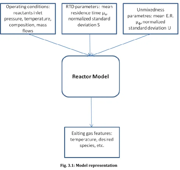
3.1.2 Model inputs
For the first stage: the model required input values related to the fuel, air, water (or steam) entering the reactor: composition, temperature, pressure. For each of them the user should define the mass flows, or more likely, the mass flows of air (or fuel) the Equivalent Ratio (E.R.) :
(3.1)
or:
(3.2) where AFRst is the air-to-fuel ratio that is a property of the fuel (e.g., 17,1897 for methane), and φ is the E.R.:
(3.3)
So E.R.=1 is defined as stoichiometric condition, conditions where there is an excess of oxidant present in the mixture are "lean", E.R.<1. Similarly, mixture with an excess of fuel are "rich", E.R.>1.
And the water-to-air ratio (ω) :
23
For the second stage: the model needs a factor R that is the ratio of the air, water, or fuel we want to inject in the second stage to the sum of the mass of the reactants in the first stage, that could be just one of the listed below:
(3.5) (3.6) (3.7) remembering that: (3.8)
so it could be determined it from the beginning.
For the RTD: both in the first and the second stage, the mean residence time (μτ) the fluid spends in the reactor or the distribution of residence time, and the normalized standard deviation (Sτ) , considering that is a Normal distribution , and the proportion of time spent in the first stage to the second stage.
for the E.R. or R distribution: similarly for the previous distribution, the model needs the mean E.R. (μφ) or for a generic ratio R (μR) in the second stage, and the normalized standard deviation (Uor SR).
3.1.3 Model outputs
The results of the model are all the characteristics of the resulting product, so the emissions of NOx, product composition and features, and the influence of residence time and grade of unmixedness have on them.
24
Fig. 3.1: Model representation
3.2 Computational instruments
For the creation of the model few computational instruments are used: first of all, Matlab[13], the main computing environment, supplemented with Cantera[14].
Cantera is an open source suite of object-oriented software tools for problems involving chemical kinetics, thermodynamics, and/or transport processes. It is a C++ based code with interfaces for Matlab but also for Python, , C, and Fortran 90, so this multi-interfacial feature makes Cantera a really flexible instrument, besides being free, and the code is modifiable by everyone, with the possibility to create new objects and enlarge its use to different kind of chemical process. Cantera is already used for modelling
![Fig. 1.2: Cumulative global energy supply investment by type in the New Policies Scenario, 2014-2035[5]](https://thumb-eu.123doks.com/thumbv2/123dokorg/7524878.106391/26.892.154.709.347.730/fig-cumulative-global-energy-supply-investment-policies-scenario.webp)