Alma Mater Studiorum
Alma Mater Studiorum –
– Università di Bologna
Università di Bologna
DOTTORATO DI RICERCA IN
CHIMICA
Ciclo XXVI
Settore Concorsuale di afferenza: 03/B2 Settore Scientifico disciplinare: CHIM-07
DESIGN AND FABRICATION OF BIOCOMPATIBLE SCAFFOLDS FOR THE
REGENERATION OF TISSUES
Presentata da: Barbalinardo Marianna
Coordinatore Dottorato
Relatore
Prof. Aldo Roda
Prof. Fabio Biscarini
Coordinatore Dottorato
Correlatore
Prof. Aldo Roda
Dr. Francesco Valle
Dedico questo lavoro di tesi a Luigi ed
a tutte le persone che hanno creduto in me
Table of Contents
Abstract
1Chapter 1. State of the art
3
1.1 Regenerative Medicine, Tissue Engineering and Nanotechnologies 3
1.2 Scaffolds 5
1.3 Scaffold fabrication: top-down & bottom-up approaches 7
Chapter 2. Experimental techniques
11
2.1Deposition and patterning 11
2.2 Scanning Electron Microscopy 15
2.3 Immuno-fluorescence assays 22
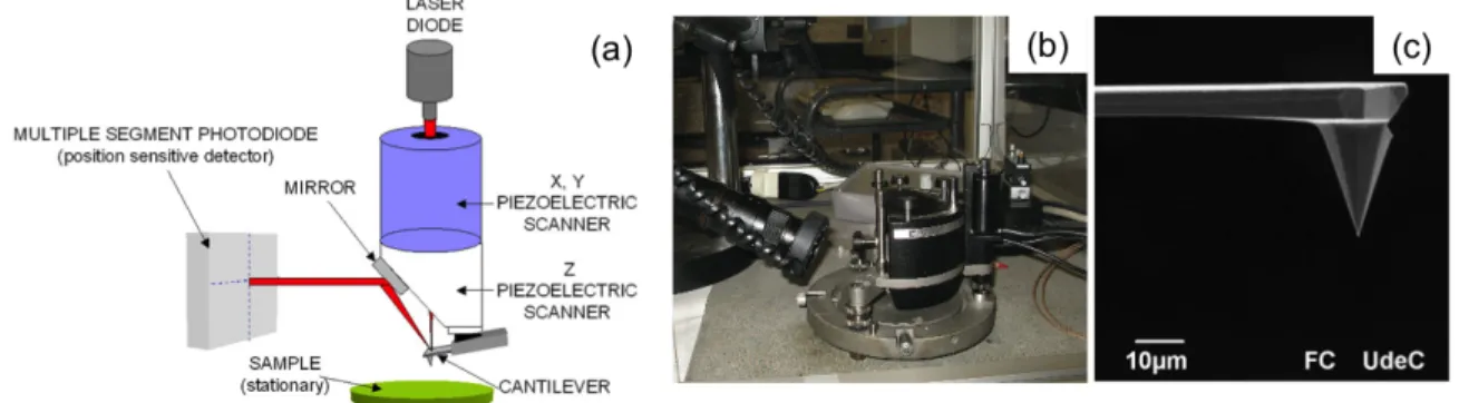
2.4 Atomic Force Microscopy 27
2.5 Cell culture
30
Chapter 3. Neuron cell alignment by pattering gradients of extracellular
matrix protein: the laminin case (2D scaffold)
35
3.1 Introduction 35
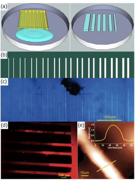
3.2 Fabrication and characterization of laminin pattern 37
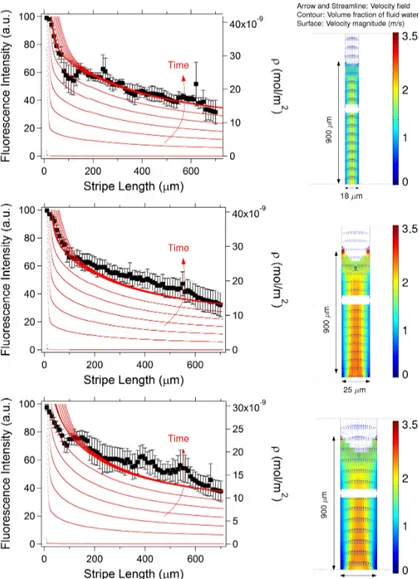
3.3 Analysis of patterned protein gradients 38
3.4 Analysis of cell nuclei orientation 41
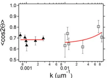
3.5 Correlation between laminin gradient and orientation order parameter 43 3.5 Conclusions
44
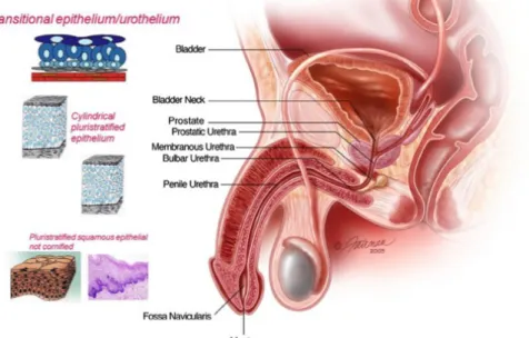
Chapter 4. Fibrin 3D-scaffolds for the reconstruction of urethra
47 4.1 Introduction 474.2 Fabrication of scaffold based on fibrin 52 4.3 Porosity analysis 55 4.4.Correlation of scaffold multiscale morphology and cell viability 58 4.5 Conclusions 60
Chapter 5. Enhancing fibrin scaffold functionality with drug
delivery
63
5.1 Introduction 63
5.2 Blending retinoic acid into fibrin scaffolds with calcium carbonate microcrystal: modulation of neuronal stem cell differentiation 65 5.3 Conclusions 70
Chapter 6. Chitin 3D-scaffold for cornea regeneration
73
6.1 Introduction 73
deacetylation 76
6.3 Cell adhesion on squid pen 78
6.4 Conclusions 81
Conclusions and Perspectives
85
Participation to meeting and conference
87
Training
88Abstract
Regenerative medicine and tissue engineering attempt to repair or improve the biological functions of tissues that have been damaged or have ceased to perform their role through three main components: a biocompatible scaffold, cellular component and bioactive molecules. Nanotechnology provide a toolbox of innovative scaffold fabrication procedures in regenerative medicine. In fact, nanotechnology, using manufacturing techniques such as conventional and unconventional lithography, allows fabricating supports with different geometries and sizes as well as displaying physical chemical properties tunable over different length scales. Soft lithography techniques allow to functionalize the support by specific molecules that promote adhesion and control the growth of cells. Understanding cell response to scaffold, and viceversa, is a key issue; here we show our investigation of the essential features required for improving the cell-surface interaction over different scale lengths. The main goal of this thesis has been to devise a nanotechnology-based strategy for the fabrication of scaffolds for tissue regeneration. We made four types of scaffolds, which are able to accurately control cell adhesion and proliferation. For each scaffold, we chose properly designed materials, fabrication and characterization techniques.
In the following chapters the different techniques and applications are described. In Chapter 1 a brief introduction on the state of art of nanotechnology, nanofabrication techniques and regenerative medicine, with a particular focus on the thematic related to fabrication of scaffolds is presented. In Chapter 2 a detailed description of the main fabrication and characterization techniques employed in this work is reported. Chapter 3 (chemical and topographical control) describes an easy route to obtain a control over cell proliferation close to 100% accuracy. The example is based on cell guidance on hydrophobic and chemically inert material such as polystyrene. Systems with controlled topography may be of interest in the field of tissue engineering to make systematic studies on the relationship between topography and cell behaviour. In Chapter 4, it is shown the fabrication, characterization and analysis of scaffolds to be used as supports for the reconstruction of the human urethra for the treatment of urethral strictures. The supports are made of a material (fibrin gel) that is biocompatible, biodegradable and already used in clinical stage and that is possible to be used to fabricate a tubular geometry. Chapter 5 describes the fabrication of a bioactive fibrin scaffold where microcrystals of calcium carbonate loaded with retinoic acid were incorporated to obtain its controlled release and the differentiation of stem cells to neurons. A key feature of some organs is to be constituted by transparent tissue, for example the eye cornea. In Chapter 6 it is shows the fabrication of a scaffold via the top-down strategy using a scaffold manufactured by nature and composed of extremely ordered chitin fibers: squid pen. The squid’s pen is a support consisting of chitin fibers trasparent, biocompatible, low cost and displaying high mechanical resistance. This material can be a great alternative to the materials used in the literature. In Chapter 7 conclusions are given.
Chapter 1
State of the art
This chapter is dedicated to a brief introduction on the state of art of regenerative medicine, nanotechnologies, nanofabrication techniques and nanobiotechnology, with a particular focus on the thematic related to the applications for scaffold fabrication.
1.1 Regenerative Medicine, Tissue Engineering and Nanotechnologies
Regenerative medicine has brought worldwide high expectations for a great number of current human illnesses. Diseases, such as Parkinson’s disease, Alzheimer’s disease, osteoporosis, spine injuries or cancer, might in the near future be treated with methods that aim at regenerating diseased or damaged tissues1. The perspective of regenerating damaged or nonfunctional tissues by using an off-the-shelf synthetic product is a driving force for medical science. Today’s interest in nanomedicine keeps growing because the application of nanotechnology tools to the development of structures at the molecular level enables the improvement of the interactions between material surfaces and biological entities2.
Nanotechnology offers promising perspectives in biomedical research and in clinical practice. Nanofibrous materials that mimic the native extracellular matrix (ECM) and promote the adhesion of various cells are being developed as tissue-engineered scaffolds for the skin, bone, vasculature, heart, cornea, nervous system, and other tissues2. A range of novel materials has been developed to enhance the bioactive or therapeutic properties of these nanofibrous scaffolds via surface modifications, including the immobilization of functional cell-adhesive ligands and bioactive molecules such as drugs, enzymes and cytokines3. As a novel approach, nanofibers prepared by using industrial scale needleless technology have been recently introduced, and their use as scaffolds to treat spinal cord injury or as cell carriers for the regeneration of the injured cornea is the subject of many recent works4. Cell therapy is a modern approach of regenerative medicine for the treatment of various diseases or injuries that is based on the accurate positioning and differentiation of stem cells. As an example, to follow the migration and fate of transplanted cells, superparamagnetic iron oxide nanoparticles have been developed for cell labelling and non-invasive monitoring of cells in the living organism, with successful applications in, e.g, the central nervous system, heart, liver and kidney and also in pancreatic islet and stem cell transplantation5.
In this strategy, the role of nanotechnology is improving of the toolbox for the construction of a biocompatible scaffold that, in combination with living cells and/or bioactive molecules,
4
replaces, regenerates or repairs damaged cells or tissue. The crucial scaffold requirements include biocompatibility, controlled porosity and permeability, physical properties comparable to the targeted tissue and, additionally, they must be a suitable support for cell attachment and proliferation. To promote cell adhesion and growth, the addition of nanotopographies to the biomaterial surface can improve its bioadhesive properties, e.g. the surface roughness, aside from the chemistry, is an important factor influencing cell attachment and spreading6. The large surface area of nanostructured materials enhances the adsorption of adhesive proteins such as fibronectin and laminin, which mediate cell-surface interactions through integrin cell surface receptors7,8. Because nanotopography have an essential role in guiding cell behaviour in vivo, it is now being used in biomaterials science as a tool for controlling tissue regeneration. A wide variety of techniques, soft-lithography includes many of them, have been used to produce nanotopography on biomaterial surfaces leading both to an ordered topography with a regular controlled pattern and to an unordered topography with random orientation and organisation.
Although cells have micrometre size, they evolve in vivo in close contact with the ECM, a substratum with topographical and structural features in the nanometre range. The interactions between cells and the ECM influence cell growth, guide cell mobility and affect the general behaviour of cells. Nanotechnologies provide the possibility to produce surfaces, structures and materials with nanoscale features that can mimic the natural environment of cells, to promote specific functions, such as cell adhesion, cell mobility and cell differentiation.
Nanomaterials used in biomedical applications include nanoparticles for molecule delivery (drugs, growth factors, DNA), nanofibres for tissue scaffolds, surface modifications of implantable materials or nanodevices, such as biosensors9,10. The combination of these elements within tissue engineering (TE) is an excellent example of the great potential of nanotechnology applied to regenerative medicine. The ideal goal of regenerative medicine is the in vivo regeneration or, alternatively, the in vitro generation of a complex functional organ consisting of a scaffold made out of synthetic or natural materials that has been loaded with living cells (Figure 1.1). Ideally, stem cells are to be used owing to their ability to generate all types of tissues and their unlimited self-renewal capacity. The functionalization of such a porous scaffold with different biomolecules (depending on the targeted cells) or the entrapment of nanoparticles carrying growth factors, drugs or genes, could enhance the success of the TE strategy greatly. However, crucial issues, such as stem cell isolation from the patient and their proliferation, the culturing process in a bio-reactor and the time delay before the engineered hybrid construct is implanted back into the patient, present major bottleneck for this approach that promise to become a well established standardised procedure in the near future.
The rapid expansion of nanotechnology during the past ten years has led to new perspectives and advances in biomedical research as well as in clinical practice. As nanotechnology is defined by the size of a material or manipulation on the molecular level, it involves a broad range of nanoscaled materials used in various fields of regenerative medicine, including TE, cell therapy, diagnosis and drug and gene delivery.
Figure 1.1: Regenerative medicine and nanotechnology approach for tissue regeneration.
1.2 Scaffolds
To regenerate a natural tissue a crucial step is to achieve the correct three-dimensional structure able to induce the adequate stimuli to the cells and to promote the tissue regrowth. Recent studies show that the isolated cells are hardly able to organize themselves spontaneously to form complex tissues in the absence of three-dimensional structures that guide them and stimulate their activities11. In almost all examined cases cultured cells tend to multiply and proliferate only in two dimensions. The three-dimensional tissue regeneration requires a support (scaffold) that emulates the ECM for the organization of cells in complex structures. Apart from blood cells, most, if not all other normal cells in human tissues are anchorage-dependent, residing in a solid matrix called ECM. There are numerous types of ECM12-14 in human tissues, which usually have multiple components and tissue-specific composition15. They can be generally classified into five categories according the function they have to carry on in the tissues and that are briefly listed here. Firstly, ECM provides structural support and physical environment for cells residing in that tissue to attach, grow, migrate and respond to signals. Secondly, ECM gives the tissue its structural and therefore mechanical properties, such as rigidity and elasticity that is associated with the tissue functions. For example, well-organized thick bundles of collagen type I in tendon are highly
6
resistant to stretching and are responsible for the high tensile strength of tendons. On the other hand, randomly distributed collagen fibrils and elastin fibers of skin are responsible for its toughness and elasticity. Thirdly, ECM may actively provide bioactive cues to the residing cells for regulation of their activities. Fourthly, ECM may act as reservoir of growth factors and potentiate their bioactivities. For instance, heparin sulfate proteoglycans facilitate bFGF dimerization and thus activities16. Fifthly, ECM provides a degradable physical environment so as to allow neovascularization and remodeling in response to developmental, physiological and pathological challenges during tissue dynamic processes namely morphogenesis, homeostasis and wound healing, respectively.
Intuitively, the best scaffold for an engineered tissue should be the ECM of the target tissue in its native state17. Nevertheless, the multiple functions, the complex composition and the dynamic nature of ECM in native tissues make it difficult to be exactly mimicked. Therefore, contemporary concept of scaffolding in TE is to mimic the functions of native ECM, at least partially. Let us consider these functions and features as follows:
• Architecture: Scaffolds should provide void volume for vascularization, new tissue formation and remodeling so as to facilitate host tissue integration upon implantation. The biomaterials should be processed to give a porous enough structure for efficient nutrient and metabolite transport without significantly compromising the mechanical stability of the scaffold. Moreover, the biomaterials should also be degradable upon implantation at a rate matching that of the new matrix production by the developing tissue.
• Cyto- and tissue compatibility: Scaffolds should provide support for either extraneously applied or endogenous cells to attach, grow and differentiate during both in vitro culture and in vivo implantation. The biomaterials used to fabricate the scaffolds need to be compatible with the cellular components of the engineered tissues and endogenous cells in host tissue.
• Bioactivity: Scaffolds may interact with the cellular components of the engineered tissues actively to facilitate and regulate their activities. The biomaterials may include biological cues such as cell-adhesive ligands to enhance attachment or physical cues such as topography to influence cell morphology and alignment. The scaffold may also serve as a delivery vehicle or reservoir for exogenous growth-stimulating signals such as growth factors to speed up regeneration. In this regard, the biomaterials need to be compatible with the biomolecules and amenable to an encapsulation technique for controlled release of the biomolecules with retained bioactivity. For example, hydrogels synthesized by covalent or ionic crosslinking can entrap proteins and release them by a mechanism controlled by the swelling of hydrogels18.
• Mechanical property: Scaffolds provide mechanical and shape stability to the tissue defect. The intrinsic mechanical properties of the biomaterials used for scaffolding or their post-processing properties should match that of the host tissue. Recent studies on mechanobiology have highlighted the importance of mechanical properties of a scaffold on the seeded cells. Exerting traction forces on a substrate, many mature cell types, such as epithelial cells, fibroblasts, muscle cells, and neurons, sense the
stiffness of the substrate and show dissimilar morphology and adhesive characteristics19.
In conclusion we can sum up that the role of the scaffold is to induce tissue regeneration by providing a "temporary guide" for cell growth, under appropriate culture conditions, to accommodate the program of differentiation20.
1.3 Scaffold fabrication: top-down & bottom-up approaches
Three-dimensional scaffolds have widespread applications in biomedical TE because of their nanoscaled architecture, eg, nanofibers and nanopores, similar to the native ECM.
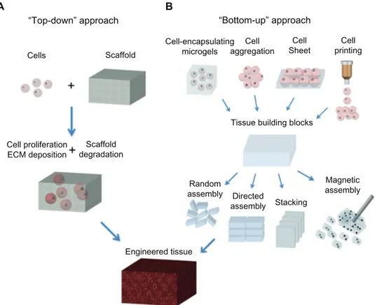
The emerging “bottom-up” method (Figure 1.2b) focuses on fabricating microscale tissue building blocks with a specific microarchitecture and assembling these units to engineer larger tissue constructs from the bottom up.
Hydrogels have widespread applications in biomedical engineering because of their hydrated environment and tunable mechanical, chemical, and biocompatibility properties which are similar to the native ECM21. Recently, the bottom-up approach has emerged as an assembly process for microscale building blocks (eg, cell-encapsulating microgels) which holds great potential to fabricate complex tissue constructs, with control over the shape and compositional features of the individual building blocks22-24. Another advantage of the bottom-up method is the superior diffusion properties of microgels due to their controllable volume, which can obtain a high cell density after encapsulating cells. A variety of methods have been developed to fabricate microgels, including molding25, folding, photolithography 26, molecular synthesis 27, and generation of microdroplets28.
In the conventional “top-down” approach (Figure 1.2a), cells are seeded onto a biocompatible and biodegradable scaffold, in which cells are expected to populate in the scaffold and create their own ECM. The top-down approach based on these scaffolds has successfully engineered thin tissues, including skin, bladder, and cartilage in vitro. However, it is still a challenge to fabricate complex and functional tissues (eg, liver and kidney) due to the lack of vascularization systems and limited diffusion properties of these large biomimetic scaffolds. The top-down approach based on a variety of three-dimensional scaffolds has been investigated for application in tissue engineering, due to the nanoscale structure of these scaffolds being analogous to that of the native ECM. For instance, in vascular tissue engineering, fabrication of small diameter (inner diameter, 6 mm) vascular grafts to meet clinical needs is still a big challenge, mostly due to the potential for thrombus formation. To address this challenge, Liu et al29 fabricated sulphated silk fibroin nanofibrous scaffolds (S-silk scaffold) with enhanced anticoagulant activity to reduce platelet adhesion and aggregation in denuded areas on the luminal surface of vascular grafts, which may prevent thrombus formation and improve the chances of successful vascular reconstruction in small vessels. For engineering of cartilage tissue, the major limitation of currently engineered cartilage is its nonhomogeneous structure and poor mechanical properties. It has also been demonstrated that oriented scaffolds (similar to cartilage tissue in vivo) could greatly improve cell migration compared with the non-oriented scaffolds achieving cartilage regeneration in
8
vitro. Thus, how to engineer three-dimensional scaffolds with regulated oriented structures and the desired mechanical properties is still a challenge.
Figure 1.2: Schematic of “top-down” and “bottom-up” approaches for tissue engineering. (A) In the top-down
approach, cells are seeded on a biocompatible and biodegradable scaffold and are expected to populate in the scaffold and create their own extracellular matrix. (B) In the bottom-up approach, various methods are utilized for generating tissue building blocks and these units can be engineered into large tissue constructs via multiple
assembling methods.
Conventional approaches to engineering tissues based on three-dimensional biomimetic scaffolds in vitro involve three steps: fabrication of three-dimensional scaffolds via different techniques including electrospinning, phase separation, freeze-drying, and self-assembly; surface modification of the prepared scaffolds to enhance their biocompatibility, especially of their synthetic polymer components; and co-culture of cells on three-dimensional porous scaffolds to regenerate tissues in vitro30. Although several thin or avascular tissues (eg, skin, bladder, and cartilage) have been engineered successfully via the top-down strategy in vitro, fabrication of complex and large functional tissues (eg, liver and kidney) with high cell densities and high metabolic requirements still faces challenges. This is mainly because of the limited diffusion properties of biomimetic scaffolds.
International Journal of Nanomedicine 2013:8
with high cell densities and high metabolic requirements still faces challenges. This is mainly because of the limited diffusion properties of biomimetic scaffolds.14 For instance,
the diffusion scale of hydrogel scaffolds is often restricted to 200 Mm due to the necrotic core.15,16 Currently, the
emerg-ing “bottom-up” method may hold great potential to address this challenge, and focuses on the fabrication of microscale tissue building blocks with a specific microarchitecture and assembling these units to engineer larger tissue constructs from the bottom up.17 Fabrication of tissue building blocks
can be achieved via multiple approaches, including fabrica-tion of cell-encapsulating microscale hydrogels (microgels), self-assembled cell aggregation, generation of cell sheets, and direct printing of cells18–20 (Figure 1). These microscale
building blocks can be successfully assembled into complex tissue constructs, with control over features such as the shape and composition of individual blocks.21,22 Various
assembly methods have been investigated, including those based on microfluidics,23 acoustic fields,24 magnetic fields,25
and surface tension.26
In this review, we firstly describe state-of-the-art methods for fabricating nanofibrous biomimetic scaffolds,
including electrospinning, phase-separation, freeze-drying, and self-assembly. A brief overview of their applications for tissue engineering is also presented. Secondly, the bottom-up methods for assembling microscale blocks (eg, microgels) including railed microfluidic assembly, surface tension assembly, acoustic assembly, and magnetic assembly are reviewed. Moreover, microfluidic hydrogels for vascular-ization are briefly presented. Finally, future perspectives for the development of techniques of construction of three-dimensional scaffolds are offered.
Fabrication of three-dimensional
biomimetic scaffolds
Many extracellular proteins, including collagen, have a nanoscale fibrous structure (50–500 nm in diameter) in vivo, which has been found to enhance cell attachment, prolif-eration, and differentiation.27,28 Nanofibrous biomimetic
scaffolds consist of biodegradable polymer nanofibers, which can be fabricated by several methods, including electrospinning, phase-separation, and self-assembly, and can mimic the nanofibrillar structure of the extracellular matrix in vivo. Here, we focus on these fabrication methods
A “Top-down” approach B “Bottom-up” approach Cells Scaffold Cell-encapsulating microgels Cell aggregation Cell
Sheet printingCell
Tissue building blocks
Magnetic assembly Directed assembly Stacking Random assembly Engineered tissue Cell proliferation
ECM deposition degradationScaffold
Figure 1 Schematic of “top-down” and “bottom-up” approaches for tissue engineering. (A) In the top-down approach, cells are seeded on a biocompatible and biodegradable
scaffold and are expected to populate in the scaffold and create their own extracellular matrix. (B) In the bottom-up approach, various methods are utilized for generating tissue building blocks and these units can be engineered into large tissue constructs via multiple assembling methods.
Abbreviation: ECM, extracellular matrix.
submit your manuscript | www.dovepress.com
Dovepress
Dovepress
338
Bibliography
1 Khang, D., Carpenter, J., Chun, Y. W., Pareta, R. & Webster, T. J. Nanotechnology for regenerative medicine. Biomed Microdevices 12, 575-‐587, (2010).
2 Boisseau, P. & Loubaton, B. Nanomedicine, nanotechnology in medicine. Cr Phys 12, 620-‐636, (2011).
3 Chen, G. P., Ushida, T. & Tateishi, T. Scaffold design for tissue engineering.
Macromol Biosci 2, 67-‐77, (2002).
4 Kubinova, S. & Sykova, E. Nanotechnologies in regenerative medicine. Minim
Invasiv Ther 19, 144-‐156, (2010).
5 Leary, J. F. Nanotechnology: what is it and why is small so big? Can J Ophthalmol 45, 449-‐456, (2010).
6 Valle, F. et al. Stable Non-‐Covalent Large Area Patterning of Inert Teflon-‐AF Surface: A New Approach to Multiscale Cell Guidance. Adv Eng Mater 12, B185-‐ B191, (2010).
7 Woo, K. M., Chen, V. J. & Ma, P. X. Nano-‐fibrous scaffolding architecture selectively enhances protein adsorption contributing to cell attachment. J Biomed Mater Res
A 67A, 531-‐537, (2003).
8 Zhu, X. L. et al. Cellular reactions of Osteoblasts to micron-‐ and submicron-‐scale porous structures of titanium surfaces. Cells, tissues, organs 178, 13-‐22, (2004). 9 Casalini, S., Leonardi, F., Cramer, T. & Biscarini, F. Organic field-‐effect transistor
for label-‐free dopamine sensing. Org Electron 14, 156-‐163, (2013). 10 Cramer, T. et al. Organic ultra-‐thin film transistors with a liquid gate for
extracellular stimulation and recording of electric activity of stem cell-‐derived neuronal networks. Phys Chem Chem Phys 15, 3897-‐3905, (2013).
11 Smith, I. O., Liu, X. H., Smith, L. A. & Ma, P. X. Nanostructured polymer scaffolds for tissue engineering and regenerative medicine. Wires Nanomed Nanobi 1, 226-‐ 236, (2009).
12 Badylak, S. F. Xenogeneic extracellular matrix as a scaffold for tissue reconstruction. Transpl Immunol 12, 367-‐377, (2004).
13 Piez, K. A. History of extracellular matrix: A personal view. Matrix Biol. 16, 85-‐92, (1997).
14 Ruan, D. K. et al. Intervertebral disc transplantation in the treatment of
degenerative spine disease: a preliminary study. Lancet 369, 993-‐999, (2007). 15 Poole, A. R. et al. Composition and structure of articular cartilage -‐ A template for
tissue repair. Clin Orthop Relat R, S26-‐S33, (2001).
16 Schonherr, E. & Hausser, H. J. Extracellular matrix and cytokines: a functional unit. Developmental immunology 7, 89-‐101, (2000).
17 Chan, B. P. & Leong, K. W. Scaffolding in tissue engineering: general approaches and tissue-‐specific considerations. Eur Spine J 17, S467-‐S479, (2008).
18 Berger, J. et al. Structure and interactions in covalently and ionically crosslinked chitosan hydrogels for biomedical applications. Eur. J. Pharm. Biopharm. 57, 19-‐ 34, (2004).
19 Discher, D. E., Janmey, P. & Wang, Y. L. Tissue cells feel and respond to the stiffness of their substrate. Science 310, 1139-‐1143, (2005).
20 Ikada, Y. Challenges in tissue engineering. J R Soc Interface 3, 589-‐601, (2006). 21 Geckil, H., Xu, F., Zhang, X. H., Moon, S. & Demirci, U. Engineering hydrogels as
10
22 Gurkan, U. A., Tasoglu, S., Kavaz, D., Demirel, M. C. & Demirci, U. Emerging Technologies for Assembly of Microscale Hydrogels. Adv Healthc Mater 1, 149-‐ 158, (2012).
23 Jensen, B. E. B. et al. Poly(vinyl alcohol) Physical Hydrogels: Noncryogenic
Stabilization Allows Nano-‐ and Microscale Materials Design. Langmuir 27, 10216-‐ 10223, (2011).
24 Xu, F. et al. Three-‐Dimensional Magnetic Assembly of Microscale Hydrogels. Adv.
Mater. 23, 4254-‐4260, (2011).
25 Diez, M. et al. Molding Micropatterns of Elasticity on PEG-‐Based Hydrogels to Control Cell Adhesion and Migration. Adv Eng Mater 13, B395-‐B404, (2011). 26 Du, Y. A., Lo, E., Ali, S. & Khademhosseini, A. Directed assembly of cell-‐laden
microgels for fabrication of 3D tissue constructs. P Natl Acad Sci USA 105, 9522-‐ 9527, (2008).
27 Qi, H. et al. Patterned Differentiation of Individual Embryoid Bodies in Spatially Organized 3D Hybrid Microgels. Adv. Mater. 22, 5276-‐5281, (2010).
28 Moon, S. et al. Layer by Layer Three-‐Dimensional Tissue Epitaxy by Cell-‐Laden Hydrogel Droplets. Tissue Eng Part C-‐Me 16, 157-‐166, (2010).
29 Liu, H. F., Li, X. M., Zhou, G., Fan, H. B. & Fan, Y. B. Electrospun sulfated silk fibroin nanofibrous scaffolds for vascular tissue engineering. Biomaterials 32, 3784-‐ 3793, (2011).
30 Khademhosseini, A. & Langer, R. Microengineered hydrogels for tissue engineering. Biomaterials 28, 5087-‐5092, (2007).
Chapter 2
Experimental techniques
In this chapter, an overview of the main techniques used for fabrication and patterning is provided. Scanning Electron Microscopy (SEM) has been used to characterize the scaffold morphology. Optical Microscopy has been used for Immuno-fluorence (IF) assays, to detect specific proteins and organelles both on the membane and inside the cell body. Atomic Force Microscopy (AFM), was performed to address in detail the scaffold morphology giving at the same time an accurate characterization of the topography.
2.1 Pattering
Soft-lithographySoft lithography describes a whole set of techniques for microfabrication, based on printing and molding using elastomeric stamps that display the patterns of interest in bas-relief. For fabricating microstructures for biological applications, soft lithography overcomes many of the shortcomings of photolithography because it allows to work with water solutions thus allowing to control the molecular structure of surfaces by patterning complex molecules such as proteins or nucleic acids. When dealing with the relatively large features used in this work (≤50 µm), production of prototype patterns is convenient, inexpensive, and rapid. Microfabrication has already proved to be crucial for life science and medicine as demonstrated by the recent combinations of disease-specific genetic information1-3 with combinatorial methods of organic synthesis4,5 and miniaturized assays for obtaining new classes of diagnostic tools6. The use of photolithography in the fabrication of DNA arrays was the first example that attracted a wide attention7,8. Although photolithography is the technology for micropatterning most common and widely used, its application to biotechnology and life science is still limited. It is intrinsically expensive, it gives limited control over surface properties, it is often not directly applicable to proteins and cells due to the use of organic solvents, the time to go from the design to prototype can be long, and the techniques are unfamiliar and inaccessible to the majority of the life science community.
Soft-lithography encompasses several techniques that share the use of elastomeric materials to fabricate by molding the pattern transfer elements, and the application to pattern complex biological molecules9-11. The main soft lithography techniques are Microcontact Printing (µcP)12,
12
Replica Molding (REM)13, MicroTransfer Molding (µTM)14, MicroMolding in Capillaries (MIMICs)12, Solvent Assisted Microcontact Molding (SAMIM)14 and Lithographically Controlled Wetting (LCW)15,16. The most used elastomeric material is polydimethylsiloxane (PDMS) and in its most widely commercialized version (Sylgard 186, Dow Chemicals) it is supplied as two components, a base and a curing agent17. PDMS displays many relevant properties. It has a Young’s modulus that makes it a moderately stiff elastomer (1 MPa). It is nontoxic and readily available commercially. It is intrinsically very hydrophobic (advancing contact angle of water of 110°), but its surface can be converted to a hydrophilic form (±10°) by common plasma treatments18.
The ability to change the surface properties of PDMS is useful when designing a stamp for transferring patterns of molecular species; the amount of material that is loaded on the stamp can be maximized by using a stamp with properties similar to those of the compound 19. PDMS is relatively permeable to nonpolar gases, including O2, N2, and CO2: this property is also essential to its use in channel systems for cell culture.
In figure 2.1 the processing steps of soft-lithographic fabrication are depicted.
Figure 2.1: The fast prototyping procedure for soft-lithpgraphy.
Starting from the original idea, the pattern is transferred to a CAD file and printed on a transparent sheet of polymer with a commercial image setter. This patterned sheet is used as a mask to prepare the master in a thin film of photoresist; a negative replica of this master with an elastomeric material becomes the stamp or mold for soft-lithography. One can start also from a commercial mask (usually of chromium/quartz or polyester) or fabricate a mask by laser ablation of a metallic thin film thus obtaining a high contrast mask20. The overall cycle from design to stamp takes less than 24 hours to be completed. However, once one has fabricated the master, multiple stamps can be obtained by Replica Molding (REM) before the master deteriorates. This is another advantage of soft-lithography compared to conventional photolithography.
Replica Molding
“Replica molding” (REM) allows the fabrication of a conformal copy of the topographic information present in a master. Being the masters usually rigid, the use of an elastomer facilitates the separation of master and replica. In REM, an appropriate elastomer such as PDMS,
enables replicating highly complex master structures with nanometer features in a simple, reliable and inexpensive way. In figure 2.2 the general replica procedure is reported. The molds are prepared by casting a mixture of PDMS and curing agent (generally in a ratio 10:1) against a rigid masters. The PDMS/master is placed in a oven at 90°C for 2 hours to complete the curing process. Then the mold is peeled off and it is ready to be used as stamp. This process can be replicated many time on the same master without damaging it.
Figure 2.2: Replica molding steps.
MicroMolding In Capillaries
MicroMolding In Capillaries is one of the most common patterning techniques based on a PDMS stamp with open-end microchannels placed brought into conformal contact with the substrate to be patterned (Figure 2.3a). A low viscosity solution is then supplied at the entrance of the capillaries at one side of the mould (Figigure 2.3b).
The solution is drawn into the microchannels by Laplace pressure (Figure 2.4c). In principle, no residue layer can form in areas where adhesive conformal contact between mould and substrate is already established. After solvent evaporation, the mould is removed to reveal patterned microstructures of the solute (Figure 2.3d).
Figure 2.3: Schematic representation of MIMICs.
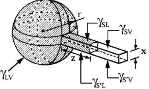
A zero order model of MIMICs is described in the following, referring to figure 2.4. First, we assume that γSV= γS’V. The liquid, whose liquid-vapor tension is γLV, fills the channel driven by Laplace pressure21:
ΔP = 2γ!" cosθ/r
The contact angle θ is defined by Young's equation:
cosθ = (γ!"− γ!")/γ
16
can be obtained by Replica Molding (REM) before the master deteriorates, allowing a great time-saving. This is another advantage of soft-lithography over conventional photolithography.
2.3 Replica Molding
REM yields a negative duplicate of the topographic information present in a master, even if three dimensional. In REM, an appropriate elastomer such as PDMS, enables replicating highly complex master structures with nanometer features in a simple, reliable and inexpensive way. The general replication procedure is reported in Figure 2.5.
Figure 2.5 Replica molding steps of a rigid master with PDMS.
The molds are prepared by casting against rigid master a mixture of PDMS and curing agent, typically in a ratio 10:1. The PDMS-master is put in an oven at 90°C for 2 hours to complete the curing process. Then the mold is peeled off and is ready to be used as stamp. This process can be replicated tens of times on the same master without introducing any defects. This is a practical protocol for manufacturing multiple copies of indistinguishable nanostructures from a single master.
2.4 MicroMolding in Capillaries
MicroMolding in Capillaries (MIMICs) is a simple and versatile soft-lithographic method that gives rise to complex microstructures on both planar and curved surfaces. It was introduced by G. M. Whitesides and co-workers in 1995[16]. MIMICs, whose scheme is reported in the Figure 2.6, can be considered as a prototype of micro- and nano-fluidics, and it can be used to pattern many soluble materials.
14
The surface tensions γSV and γSL depend on the substrate and the channel walls, and r is the effective diameter of the channel.
Figure 2.4: A model for MIMICs. A fluid is assumed to move from a spherical drop (radius r) into a square channel
(width x) with three identical surfaces (PDMS) and one different (the substrate). The terms γSV, γSL, and γLV
corresponds to interfacial free energies of solid-vapor, solid-liquid and liquid-vapor interfaces22.
The rate of the liquid flow22 in the capillary is determined by the ratio of surface tension and viscosity of the liquid, the cross-sectional size of the capillary and the length of the channel by the following equation23 :
dz dt = Rγ!"cosθ 4ηz = R(γ!"− γ!") 4ηz
where z is the length of the liquid capillary inside the channel, η is the viscosity of the penetrating liquid, R is the ratio between capillary volume and the surface area of the channel, and θ is the contact angle of the fluid meniscus inside the capillary. The surface tensions γLV, γSV and γSL are the surface tensions between liquid and air, channel wall and air, and channel wall and liquid, respectively. It follows upon integration that:
z t = R γ!"2η− γ!" t
The equation shows that although the capillary force of a channel increases with decreasing hydraulic radius R, this effect is more than counterbalanced by the increased friction exerted by the channel walls, so that the filling rates are lower in smaller channels.
The shape of the imbibition front of the liquid precursors has been studied in detail24. Depending on the surface energy of the channel wall γSV, different spreading regimes can be observed, as illustrated in the figure 2.5.
18
A zero-th order model of MIMICs is described in the following, referring to Figure 2.7. First, we assume that γSV= γS’V. The liquid, whose liquid-vapor tension γLV, fills the channel driven by
Laplace pressure[17]:
∆𝑃 = 2𝛾 cos 𝜃 𝑟⁄ . The contact angle θ is defined by Young's equation:
cos 𝜃 = (𝛾 − 𝛾 ) 𝛾⁄ .
The surface tensions γSV and γSL depend on the substrate and the channel walls, and r is the
effective diameter of the channel.
Figure 2.7 A model for MIMICs. A fluid is assumed to move from a spherical drop (radius r) into a square channel (width x) with three identical surfaces (PDMS) and one different (the substrate). The terms γSV,
γSL, and γLV corresponds to interfacial free energies of solid-vapor, solid-liquid and liquid-vapor interfaces
(from G. M. Whitesides et al.[9])
The rate of the liquid flow[16] in the capillary is determined by the ratio of surface tension and
viscosity of the liquid, the cross-sectional dimension of the capillary and the length of the channel by the follow equation[18]:
𝑑𝑧 𝑑𝑡 = 𝑅𝛾 cos 𝜃 4𝜂𝑧 = 𝑅(𝛾 − 𝛾 ) 4𝜂𝑧
where R is the hydrodynamic radius, the ratio between the volume of the liquid in the capillary section and the area of the solid and liquid interface, η the viscosity of the liquid, z the length of the column of liquid (Figure 2.7). Upon integration of the differential equation, one obtains the filling distance vs time:
Figure 2.5: Schematic representation of different spreading regimes observed in MIMIC. Shapes of the penetrating
liquids in PDMS capillaries are formed inside (a) walls with low γSV (b and c) walls with medium γSV, and (d) walls
with high γSV.
Liquids penetrating inside a channel with low surface energy walls, exhibit capillary fronts that advance as a whole. As the surface energy of the channel increases, solute structures advancing in front of the macroscopic body of liquid are observed, especially in the corners between mold and substrate. Some of these structures include slipping films and shoulders. Similar regimes have been observed with differences in the velocity of imbibition on surfaces with constant γSV25 .
MIMIC is a microfabrication method that works well with many different materials but at its current stage of development has also some limitations. The rate of capillary filling is rapid and complete over short distances while, over a large distance, it decreases significantly owing to the viscous drag of the fluid in the capillary. The forward ends of capillaries may fill incompletely if the hydraulic drag is sufficiently high. The rate of filling also decreases as the cross-sectional dimension of the capillary decreases and as the interfacial free energy of the surface decreases24.
2.2 Scanning Electron Microscopy
Scanning electron microscopy (SEM) is one of the most versatile techniques available for the examination and analysis of the microstructure morphology and for the characterization of their chemical composition. The unaided eye can discriminate objects subtending about 1/60 ̊ visual angle, corresponding to a resolution of ~0.1 mm (at the optimum viewing distance of 25 cm). The limit of resolution is defined as the minimum distances where two structures can be separated still appearing as two distinct objects. Ernst Abbe26 proved that the limit of resolution depends on the wavelength of the illumination source. At a defined wavelength, when resolution exceeds this limit, the magnified image starts blurring. Because of diffraction and interference, a point of light cannot be focused as a perfect dot, the image will rather have the appearance of a larger diameter than the source, consisting of a disk composed of concentric circles with decreasing intensity. This is known as an Airy disk and is represented in figure 2.6a. The primary wave front contains approximately 84% of the light energy, and the intensity of secondary and tertiary wave fronts
25
where θmould and θsubstrate are the contact angles of the liquid with the surfaces of the mould and the
substrate, respectively.
The shape of the imbibition front of liquid precursors has been studied in detail18. Depending on the
surface energy of the channel wall γSV, different spreading regimes can be observed, as illustrated in
Fig. 2.9.
Fig. 2.9. Schematic representation of different spreading regimes observed in MIMIC. Shapes of the penetrating liquids in PDMS capillaries are formed inside (a) walls with low γSV, (b and c) walls with
medium γSV, and (d) walls with high γSV.
Liquids penetrating inside a channel with low surface energy walls, show capillary fronts that advance as a whole. But as the surface energy of the channel increases, solute structures advancing in front of the macroscopic body of liquid are observed, especially in the corners between mould and substrate. Some of these structures include slipping films and shoulders. Similar regimes have been observed with differences in the velocity of imbibition on surfaces of constant γSV.
16
decay rapidly at higher orders. Generally, the radius of Airy disk is defined as the distance between the first-order peak and the first-order trough, as shown in figure 2.6a. When the center of two primary peaks are separated by a distance equal to the radius of Airy disk, the two objects can be distinguished from each other, as shown in figure 2.6b. Resolution, in a perfect optical system, can be described mathematically by Abbe’s equation. In this equation:
𝒅 = 𝟎. 𝟔𝟏𝟐 𝝀 𝒏 𝒔𝒊𝒏 𝜶
where d is the resolution, λ the wavelength of imaging radiation, n the refractive index of the medium between the point source and the lens relative to free space, α is half the angle of the cone of light from specimen plane accepted by the objective (half aperture angle in radians), n sin α is often called numerical aperture (NA).
Substituting the illumination source and condenser lens with electron beam and electromagnetic coils in light microscopes, respectively, the first transmission electron microscope (TEM) was constructed in the 1930s27, in which electron beam was focused by an electromagnetic condenser lens onto the specimen plane. The SEM uses a focused electron beam scanned across the surface of the specimen systematically thus producing a large number of signals (secondary electrons, back-scattered electrons, chatacteristic X-ray, Auger electrons, cathodoluminescence, transmitted electrons and specimen current). These electron signals are eventually converted to a visual signal.
Figure 2.6: Illustration of resolution in (a) Airy disk and (b) wave front.
Image formation in the SEM is dependent on the acquisition of the signals produced by the interactions of the electron beam with the samples. These interactions can be divided into two major categories: elastic and inelastic.
Elastic scattering results from the deflection of the incident electrons by the sample atomic nuclei or by the outer shell electrons of similar energy. This kind of interaction is characterized by negligible energy loss during the collision and by a wide-angle directional change of the scattered electron. Incident electrons that are elastically scattered through an angle of more than 90 ̊ are called backscattered electrons (BSE), and yield a useful signal for imaging the sample. Inelastic scattering occurs through a variety of interactions between the incident electrons and the electrons and atoms of the sample, and results in the primary beam electron transferring substantial energy to that atom. The amount of energy loss depends on whether the specimen electrons are excited singly or collectively and on the binding energy of the electron to the atom. the first-order trough, as shown in Fig. 1.1a. When the center of two primary peaks
are separated by a distance equal to the radius of Airy disk, the two objects can be distinguished from each other, as shown in Fig. 1.1b. Resolution in a perfect opti-cal system can be described mathematiopti-cally by Abbe’s equation. In this equation:
d= 0.612 l /n sin a where
d= resolution
l = wavelength of imaging radiation
n= index of refraction of medium between point source and lens, relative to free space
a = half the angle of the cone of light from specimen plane accepted by the objec-tive (half aperture angle in radians)
nsin α is often called numerical aperture (NA).
Substituting the illumination source and condenser lens with electron beam and electromagnetic coils in light microscopes, respectively, the first transmission electron microscope (TEM) was constructed in the 1930s [2], in which electron beam was focused by an electromagnetic condenser lens onto the specimen plane. The SEM utilizes a focused electron beam to scan across the surface of the spec-imen systematically, producing large numbers of signals, which will be discussed in detail later. These electron signals are eventually converted to a visual signal displayed on a cathode ray tube (CRT).
1.1.1. Interaction of Electron with Samples
Image formation in the SEM is dependent on the acquisition of signals produced from the electron beam and specimen interactions. These interactions can be divided into two major categories: elastic interactions and inelastic interactions.
2 Weilie Zhou et al.
(a)
(b)
FIGURE1.1. Illustration of resolution in (a) Airy disk and (b) wave front.
the first-order trough, as shown in Fig. 1.1a. When the center of two primary peaks are separated by a distance equal to the radius of Airy disk, the two objects can be distinguished from each other, as shown in Fig. 1.1b. Resolution in a perfect opti-cal system can be described mathematiopti-cally by Abbe’s equation. In this equation:
d= 0.612 l /n sin a where
d= resolution
l = wavelength of imaging radiation
n= index of refraction of medium between point source and lens, relative to free space
a = half the angle of the cone of light from specimen plane accepted by the objec-tive (half aperture angle in radians)
nsin α is often called numerical aperture (NA).
Substituting the illumination source and condenser lens with electron beam and electromagnetic coils in light microscopes, respectively, the first transmission electron microscope (TEM) was constructed in the 1930s [2], in which electron beam was focused by an electromagnetic condenser lens onto the specimen plane. The SEM utilizes a focused electron beam to scan across the surface of the spec-imen systematically, producing large numbers of signals, which will be discussed in detail later. These electron signals are eventually converted to a visual signal displayed on a cathode ray tube (CRT).
1.1.1. Interaction of Electron with Samples
Image formation in the SEM is dependent on the acquisition of signals produced from the electron beam and specimen interactions. These interactions can be divided into two major categories: elastic interactions and inelastic interactions.
2 Weilie Zhou et al.
(a)
(b)
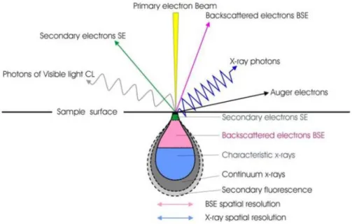
As a result, the excitation of the specimen electrons during the ionization of specimen atoms leads to the generation of secondary electrons (SE), which are conventionally defined as possessing energies of less than 50 eV and can be used to image or analyze the sample. In addition to those signals that are utilized to form an image, a number of other signals are produced when an electron beam strikes the sample surface, including the emission of characteristic x-rays, Auger electrons, and cathodoluminescence (Figure 2.7).
Figure 2.7: Shows the regions from which different signals are detected (from University of Glasgow Imaging
Spectroscopy and Analysis Centre).
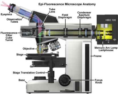
The main components of a typical SEM are the electron column, the scanning system, the detector(s), the display, the vacuum system and the electronics controls (Figure 2.8). Below the description of the main components of the SEM is reported.
18
Figure 2.8: Schematic representation of SEM.
Electron Guns
The electron column, which is on the top of the column, consists of an electron gun and two or more electromagnetic lenses operating in vacuum. The electron gun generates free electrons and accelerates these electrons to energies in the range 1-40 keV in the SEM. The purpose of the electromagnetic lenses is to create a small, focused electron probe on the specimen. Most SEMs can generate an electron beam with a spot size at the specimen surface of less than 10 nm in diameter.
In this work we used a SEM Hitachi S4000, a field emission electron guns (FEG). In a FEG, a single crystal tungsten wire with very sharp tip, generally prepared by electrolytic etching, is used as the electron source. Figure 2.9a and b shows a micrograph of a typical field emission tip and the schematic structure of the FEG. There are three types of FEGs commonly used in the SEM systems: cold field emission, thermal field emission and Schottky emitters 28. Hitachi S4000 is a cold field emission (CFE) sources. The “cold field” means the electron sources operate at room temperature. The emission of electrons from the CFE purely depends on the electric field applied between the anodes and the cathode. Although the current of the emitted electron beams is very small, a high brightness can still be achieved because of the small electron beam diameter and emission area. An operation known as “flashing” in which the field emission tip is heated to a temperature of more than 2,000 K for a few seconds is needed to clean absorbed gas on the tip. Compared with thermionic sources, CFE provides enhanced electron brightness, typically 100X greater compared to a typical tungsten source. However, field emitters must operate under ultrahigh vacuum to stabilize the electron emission and to prevent contamination.
Figure 2.9: (a) Field emission source with extreme sharp tip; (b) a higher magnification image; and (c) schematic
diagram of a typical field emission electron source. The two anodes work as an electrostatic lens to form electron beams.
Electron Lenses
The purpose of the electron lenses is to produce a convergent electron beam with desired crossover diameter. The lenses are metal cylinders with cylindrical hole, operated in vacuum. Inside the lenses a magnetic field is generated, which in turn is varied to focus or defocus the electron beam passing through the hole of the lens.
SEMs employ one to three condenser lenses to demagnify the electron-beam crossover diameter in the electron gun to a smaller size. The first and second condenser lenses control the amount of demagnification. Usually in the microscopes this is a single control labeled “spot size”, “condenser”, “C1” or “resolution”. The final lens in the column sometimes inappropriately called “objective” focuses the probe on the sample. The design of the lenses often incorporates space for the scanning coils, the stigmator, and the beam limiting aperture. The electron lenses can be used to magnify or demagnify the electron beam diameter, because their strength is variable, which results in a variable focal length. SEM always uses the electron lenses to demagnify the “image” of the emission source so that a narrow probe can be formed on the surface of the specimen. The aberrations of the final lens and consequently the resolution are controlled by a final lens aperture, which affects the beam convergence angle.
The final lens aperture has three important effects on the final probe. First there is an optimum aperture angle that minimizes aberrations. Second, the current in the final probe is controlled by the size of the aperture. Third, the probe convergence angle α controls the depth of field. Smaller α produces greater depth of field. Spot size in SEM is minimized at the expense of current.
The general approach in SEM is to minimize the probe diameter and maximize the probe current. The minimum probe diameter depends on the spherical aberration of the SEM electron optics, the gun source size, the electron optical brightness and the accelerating voltage.
The probe size, which directly effects resolution can be decreased by increasing the brightness. The electron optical brightness ß is a parameter that is function of the electron gun performance and design. For all types of electron guns, brightness increases linearly with accelerating voltage,
inexpensive and the requirement of vacuum is relatively low, the disadvantages, such as short lifetime, low brightness, and large energy spread, restrict their appli-cations. For modern electron microscopes, field emission electron guns (FEG) are a good alternative for thermionic electron guns.
In the FEG, a single crystal tungsten wire with very sharp tip, generally pre-pared by electrolytic etching, is used as the electron source. Figure 1.12a and b shows a micrograph of a typical field emission tip and the schematic structure of the FEG. In this system, a strong electric field forms on the finely oriented tip, and the electrons are drawn toward the anodes instead of being boiled up by the filament heating. Two anodes are used in field emission system, depicted in Fig. 1.12c. The voltage V1with a few kilovolts between the tip and the first anode is used to extract the electrons from the tip, and the V0is the accelerating voltage. There are three types of FEGs that are used in the SEM systems [5]. One is the cold field emission (CFE) sources. The “cold field” means the electron sources operate at room temperature. The emission of electrons from the CFE purely depends on the electric field applied between the anodes and the cathode. Although the current of emitted electron beams is very small, a high brightness can still be achieved because of the small electron beam diameter and emission area. An operation known as “flashing” in which the field emission tip is heated to a temperature of more than 2,000 K for a few seconds is needed to clean absorbed gas on the tip. The second class is thermal field emission (TFE) sources, which is operated in elevated temperature. The elevated temperature reduces the absorption of gas molecules and stabilizes the emission of electron beam even when a degraded vacuum occurs. Beside CFE and TFE sources, Schottky emit-ters (SE) sources are also used in modern SEM system. The performances of SE and CFE sources are superior to thermionic sources in the case of brightness, source size, and lifetime. However, SE source is preferred over CFE source because of its higher stability and easier operation. Because the emitting area of SE source is about 100× larger than that of the CFE source, it is capable to deliver more than 50× higher emission current than CFE at a similar energy spread. Further, a larger size of emission source reduces the susceptibility to vibration.
14 Weilie Zhou et al.
(a) (b) (c) 1 mm 300 µm First anode second anode V0 V1
FIGURE1.12. (a) Field emission source with extreme sharp tip; (b) a higher magnification
image; and (c) schematic diagram of a typical field emission electron source. The two anodes work as an electrostatic lens to form electron beams.
20
so every electron source is 10 times as bright at 10 kV as it is at 1 kV. Decreasing the wavelength and the spherical aberration also decreases the probe size.
The lens defects (machining errors and asymmetry in lens winding), and contamination on aperture or column can cause the cross section of the electron beam profile to vary in shape. Generally, an elliptical cross section is formed rather than a circular one. As a result, during operation, the image will stretch along different direction at underfocus and overfocus condition. This imperfection on the electromagnetic lens is called astigmatism. A series of coils surrounding the electron beam, referred to as “stigmator,” can be used to correct astigmatism and achieve an image with higher resolution.
The astigmatism correction cycle (x-stigmator, focus, y-stigamator, focus) should be repeated, until ultimately the sharpest image is obtained. At that point the beam cross section will be focused to the smallest point. Generally the compensation for astigmatism is performed while operating at the increased magnification, which ensures the image quality of lower magnification even when perfect compensation is not obtained. However, the astigmatism is not obvious for low magnification observation.
Image Formation
The SEM image is a 2D intensity map in the analog or digital domain. Each image pixel on the display corresponds to a point on the sample, which is proportional to the signal intensity captured by the detector at each specific point (Figure 2.10). Unlike optical or transmission electron microscopes no true image exists in the SEM. It is not possible to place a film anywhere in the SEM and record an image. It does not exist. The image is generated and displayed electronically. The images in the SEM are formed by electronic synthesis, no optical transformation takes place, and no real of virtual optical images are produced in the SEM26.
Figure 2.10: Image formation by SEM.
In an analog scanning system, the beam is moved continuously; with a rapid scan along the X-axis (line scan) supplemented by a stepwise slow scan along the Y-X-axis at predefined number of lines. The time for scanning a single line multiplied by the number of lines in a frame gives the frame time. In digital scanning systems, only discrete beam locations are allowed. The beam,
4 electrons strike a specimen they penetrate inside it to depths of about 1 µm and interact both elastically and inelastically with the solid, forming a limiting interaction volume from which various types of radiation emerge, including BSE, SE, characteristic and brehmsstrahlung x-rays, and cathodoluminescence in some materials.
The combined effect of elastic and inelastic scattering controls the penetration of the electron beam into the solid. The resulting region over which the incident electrons
interact with the sample is known as interaction volume. The interaction volume has
several important characteristics, which determine the nature of imaging in the SEM. The energy deposition rate varies rapidly throughout the interaction volume, being greatest near the beam impact point. The interaction volume has a distinct shape (fig. 2). For low-atomic-number target it has distinct pear shape. For intermediate and high-atomic number materials the shape is in the form of hemi-sphere.
The interaction volume increases with increasing incident beam energy and decreases with increasing average atomic number of the specimen. For secondary electrons the sampling depth is from 10 to 100 nm and diameter equals the diameter of the area emitting backscattered electrons. BSE are emitted from much larger depths compared to SE.
Ultimately the resolution in the SEM is controlled by the size of the interaction volume.
Image formation
The SEM image is a 2D intensity map in the analog or digital domain. Each image pixel on the display corresponds to a point on the sample, which is proportional to the signal intensity captured by the detector at each specific point (fig.3). Unlike optical or transmission electron microscopes no true image exists in the SEM. It is
not possible to place a film anywhere in the SEM and record an image. It does not exist. The image is generated and displayed electronically. The images in the SEM are formed by electronic synthesis, no optical transformation takes place, and no real of virtual optical images are produced in the SEM.
In an analog scanning system, the beam is moved continuously; with a rapid scan along the X-axis (line scan) supplemented by a stepwise slow scan along the Y-axis at predefined number of lines. The time for scanning a single line multiplied by the number of lines in a frame gives the frame time. In digital scanning systems, only discrete beam locations are allowed. The beam is positioned in a particular location remains there for a fixed time, called dwell time, and then it is moved to the next point.
When the beam is focused on the specimen an analog signal intensity is measured by the detector. The voltage signal produced by the detector’s amplifier is digitized and stored as discrete numerical value in the corresponding computer registry. Typically, the intensity is digitized into 8 bits (256 levels), 12 bits (4096) or 16 bits (65,536). The digital image is viewed by converting the numerical values stored in the computer memory into an analog signal for display on a monitor.
Lmon
Area on specimen Image monitor Information
transfer
Figure 3 Lspec