Alma Mater Studiorum – Università di Bologna
DOTTORATO DI RICERCA IN
Meccanica e Scienze Avanzate dell’Ingegneria
Ciclo XXX
Settore Concorsuale: 09/C1
Settore Scientifico Disciplinare: ING-IND/08
OPTIMIZATION STRATEGIES FOR COMPLEX ENERGY NETWORKS
WITHIN DISTRIBUTED GENERATION
Presentata da:
Maria Alessandra Ancona
Coordinatore Dottorato
Supervisore
Prof. Marco Carricato
Prof. Francesco Melino
Contents
Introduction ... 1
Structure of the manuscript ... 3
Nomenclature ... 5
1. Complex Energy Networks and Distributed Generation ... 6
References ... 12
2. District Heating Networks... 14
References ... 21
3. DHNs design and analysis ... 24
3.1 The Todini-Pilati algorithm ... 24
3.2 Software Ca.R.Di.F. ... 27
3.3 Software validation. ... 30
References ... 34
4. Smart District Heating ... 35
4.1 Users substations in Smart District Heating Networks ... 35
4.2 Software IHENA ... 38
4.3 Thermodynamic considerations on the proposed schemes ... 40
4.4 Transformation hypothesis for the conversion of an existing user substation into a
smart one ... 45
4.4.1 Case 1 ... 50
4.4.2 Case 2 ... 58
5. Scheduling optimization methods in complex energy networks ... 69
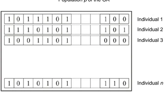
5.1 Genetic algorithms ... 69
5.2 Mixed Integer Linear Programming models ... 72
5.3 Mixed Integer Non-Linear Programming models ... 74
References ... 76
6. Software EGO ... 78
6.1 Calculation model ... 78
6.2 Software test versus alternative approach ... 83
References ... 88
7. Optimization analysis – case study I ... 89
7.1 DHN current set-up ... 89
7.2 Phase I: thermal needs fulfillment ... 91
7.2.1 Thermal needs profile definition ... 92
7.2.2 Case studies: characteristics and assumptions ... 94
7.2.3 Results and discussion ... 98
7.3 Phase II: thermal, electrical and cooling energy fulfillment ... 105
7.3.1 Energy needs analysis ... 105
7.3.2 Optimal management strategies – Case studies ... 111
7.3.3 Results and discussion ... 117
References ... 135
8. Optimization analysis – case study II ... 137
8.1 Case Study ... 137
8.2 Energy Systems ... 140
8.3 Energy Systems Off-design Operation and Others Assumptions ... 145
8.4 Energy Results ... 148
8.5 Economic and Environmental Results ... 153
9. MILP optimization – comparison ... 160
9.1 Case Study ... 160
9.2 Software MEGS ... 161
9.3 Results ... 163
9.3.1 DHN design ... 163
9.3.2 Energy systems operation ... 164
9.3.3 Computational time ... 165
9.3.4 Integration between GA and MILP approaches ... 165
References ... 167
Conclusions ... 168
List of Tables ... 172
List of Figures ... 173
Appendix A ... 180
Appendix B ... 183
Appendix C ... 187
1
Introduction
In many European countries, the amount of distributed generation systems has been considerably increased in the last years, mainly due to the EU energy targets – first of all the so-called “20-20-20” strategy – and to the related national energy policies enforcement. Furthermore, the European strategy 20-20-20 – providing for energy efficiency increase, pollutant emissions reduction and fossil fuel consumption reduction – leads to an increasing attention on the concept of smart cities. In the next years energy grids are expected to become increasingly complex, due to the integration between traditional generators (operating with fossil fuels, especially natural gas), renewable energy production systems and storage devices. In addition to the well-known and largely diffused electricity smart grids, the new concept of smart thermal network – and, in particular, smart district heating – has been recently developed. In fact, the possibility to allow a bidirectional heat exchange at final users, where solar thermal panels or small-size combined heat and power units are installed, seems to be a promising solution for the global conversion efficiency increase.
On the other hand, the increase in installed distributed generation systems is posing new issues for the existing grids. The integration involves both electric grids and thermal networks, such as district heating networks. As it regards electricity grids, the presence of non-programmable renewable sources causes some issues on grid frequency and stability, as well as the possibility of black-out events in case of wrong demand forecast and plants management. On the other hand, relating to thermal distribution networks (i.e. district heating networks), the idea of directly integrating distributed systems entails – in particular – the temperature levels of the network and, consequently, a correct district heating management is required.
In this scenario, it is fundamental to optimize the production mix and the operation of each system, in order to maximize the renewable energies exploitation, minimize the economic costs (in particular the fossil fuel consumption) and the environmental impact. As a result, one of the main purposes relating to the smart grids is the optimization of the scheduling (i.e. the load distribution) of the various energy production systems, which concur to the satisfaction of energy demand.
The determination of ideal systems set-up, as well as the control and operation of the integrated network, is not easy. With this purpose, several optimization algorithms can be applied, such as genetic algorithm (GA), particle swarm optimization and firefly algorithm – as it concerns heuristic models – or Linear Programming, Mixed Integer Linear Programming (MILP) and Mixed Integer Non Linear Programming (MINLP) models, as it regards exact methods. As it concerns energy networks, genetic algorithms and MILP based models are the most widely used for the scheduling optimization problems. Furthermore, MINLP models are considered as an interesting way, but further efforts have to be made in order to maintain the nonlinear complexity of the problem and an admissible computation time (the temporal horizon is usually 1 year of operation).
The aim of this Ph. D thesis is to investigate the complex energy networks scenario and elaborate innovative strategies and methods for the optimization of the energy systems scheduling (i.e. the optimal load allocation), in order to fulfill given electric, thermal and cooling needs of the users.
2
To this purpose, specific calculation codes have been developed and applied. The main objectives at the basis of the here presented work have been: (i) the minimization (or avoidance) of the electricity exchange with the national grid, (ii) the minimization (or avoidance) of the heat dissipations through the chimney, (iii) the minimization of the auxiliary boilers employment, (iv) the optimization of the cogeneration units operation and (v) the maximization of the renewable sources exploitation.
Innovative aspects of the work stand also in the definition of new configurations for user substation within district heating networks, in order to allow the bidirectional heat exchange and the transformation of the traditional networks into smart district heating networks.
3
Structure of the manuscript
This thesis is divided into four main parts:
Part I. The first part presents an overview of the scenarios of interest and motivates the work by
outlining the fundamental key aspects concerning the integration between energy distribution networks and distributed generation systems. In particular, Chapter 1 presents an overview of the concept of complex energy networks and distributed generation technologies. Chapter 2, instead, focuses on the state of the art of district heating networks, considering both the World and the Italian contest.
Part II. In this section a thermo-hydraulic analysis on district heating has been carried out. In
particular, in Chapter 3 the mathematical model of an in-house developed software (called Ca.R.Di.F. – Calcolo Reti Distribuzione Fluidi) for the design and analysis of district heating and cooling networks is presented, along with its validation. To this purpose, a comparison with a commercial software on a case study is presented and discussed. Then, in Chapter 4 the concept of smart district heating is deeply investigated. In detail, four elaborated innovative configurations for users substations, able to guarantee the bidirectional heat exchange, are described and their implementation into the Ca.R.Di.F. software is shown, giving birth to the new software IHENA (Intelligent Heat Network Analysis). Furthermore, the effects of the four configurations on the network have been thermodynamically analyzed, with the help of a case study, and two different transformation hypotheses for the conversion of an existing user substation into a smart one have been conceived. For each of the proposed transformation hypotheses, a specific logic of operation has been elaborated and a techno-economic analysis has been carried out.
Part III. The third part of this thesis focuses on the scheduling optimization within complex
energy networks. In Chapter 5 the state of the art of the main algorithms currently applied for the optimization of the energy systems load allocation is discussed, while in Chapter 6 the mathematical model of the in-house developed software EGO (Energy Grid Optimizer), based on genetic algorithms, is presented. This software has been applied to several case studies: the most representatives are discussed in Chapter 7 (middle size district energy network ) and in Chapter 8 (isolated grid). In detail, indeed, in Chapter 7, starting from the current configuration and operation set-up, new optimized strategies for users’ needs fulfillment in an existing middle size district heating network have been evaluated. Two different approaches have been investigated: the first one considers the fulfillment only of the thermal needs of the users while the second one adds the electricity and cooling energy fulfillment. For both of these approaches, various energy systems set-up have been hypothesized (including renewable energy systems, heat pumps, cogenerators, compression and absorption chillers, etc.) and the energy systems scheduling has been optimized by means of EGO. A comparison – from both economic and environmental points of view – has been carried out in order to define the most suitable technologies for the analyzed
4
case study. On the other hand, in Chapter 8 a particular application of isolated grid, i.e. a cruise ship, has been analyzed. As for the previous case, several energy systems set-up have been proposed, operationally optimized with the software EGO and comparatively analyzed, in order to find the best solution for the given cruise demand profile (in terms of electrical, thermal and cooling energy).
Part IV. Chapter 9 describes the comparison between genetic algorithms and MILP models to
solve scheduling optimization problems, carried out during the PhD period abroad, at the École Polytechnique Fédérale de Lausanne (EPFL) – Valais offices. In more detail, the main characteristics of the MEGS software, developed by EPFL, are described and the results of its application to a case study are compared to the ones of the software EGO, outlining pro and cons of both the approaches.
Acknowledgments
A number of persons have directly or indirectly contributed to this research. I thank in particular my advisor, Prof. Francesco Melino, and the whole research group, Prof. Michele Bianchi, Prof. Antonio Peretto and Prof. Andrea De Pascale. I would like to thank also my colleagues, in particular Lisa Branchini and Valentina Orlandini, for their continuous support and friendship during my PhD years.
5
Nomenclature
Abbreviations AB Auxiliary Boiler AC Absorption Chiller BB Biomass BoilerCaRDiF Calcolo Reti Distribuzione Fluidi CC Compression Chiller
CHP Combined Heat and Power DG Distributed Generation DH District Heating
DHN District Heating Network EES Electrical Energy Storage EGO Energy Grid Optimizer FC Fuel Cell
FF Fitness Function FFA FireFly Algorithm GA Genetic Algorithm GT Gas Turbine HE Heat Exchanger HP Heat Pump
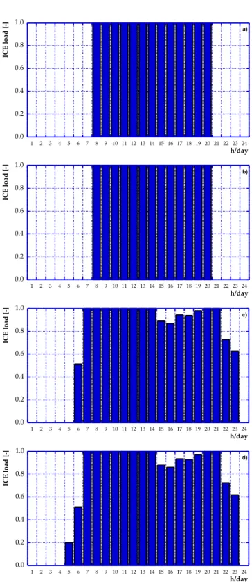
ICE Internal Combustion Engine
ICT Information & Communication Technology IHENA Intelligent Heat Network Analysis
LP Linear Programming MDO Marine Diesel Oil
MEGS Multi Energy Grid Systems MGT Micro Gas Turbine
MILP Mixed Integer Linear Programming MINLP Mixed Integer Non Linear Programming PM Prime Mover
PSO Particle Swarm Optimization PV PhotoVoltaic
RES Renewable Energy Source RG Renewable Generator
SDHN Smart District Heating Network SST Storage Tank
TES Thermal Storage TSP Thermal Solar Panels
Symbols 𝐴 area [m2] CF fixed cost [€]
cl liquid specific heat [kJ/kg°C] COP Coefficient Of Performance [-] CT total cost [€]
CV variable costs [€] ∆𝐻 pressure losses [Pa] 𝐷 diameter [m] E energy [kWh]
EER Energy Efficiency Ratio [-] F fuel consumption [kWh] 𝑓 drag coefficient
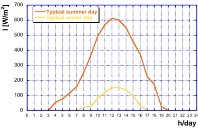
𝐻 energy content of fluid [Pa] I solar irradiation [W/m2] IC incremental cost [€/kW] 𝐿 length [m]
𝑚̇ mass flow rate [kg/s] 𝑣 mean velocity [m/s] p pressure [bar] 𝑃 perimeter [m] P electrical power [kW] Q thermal power ROI return of investment [y] 𝑅𝑒 Reynolds number [-] S surface [m2] T temperature [°C]
𝑈 global heat exchange coefficient [W/m2K] V volume [m3]
Greek symbols
𝛼 convection coefficient [W/m2K] 𝛽 coeff. of concentrated pressure losses [-] 𝜀 roughness [mm]
Η efficiency [-]
𝜆 conduction coefficient [W/mK] 𝜇 dynamic viscosity [Pa∙s]
ξ specific cost [€/kW] 𝜌 density [kg/m3]
Subscripts and superscripts 𝑐𝑜𝑛𝑐 concentrated des design 𝑑𝑖𝑠 distributed 𝑑𝑖𝑠𝑠 dissipated e electrical 𝑒𝑥𝑡 external F fictitious ℎ hydraulic 𝐼𝑁 at the inlet 𝑖𝑛𝑠 insulating 𝑖𝑛𝑡 internal M maintenance 𝑚 mean max maximum min minimum 𝑂𝑈𝑇 at the outlet 𝑝 pipe P purchase S sale th thermal 𝑢 user
6
1. Complex Energy Networks and
Distributed Generation
In the last years, energy grids became a central issue for the achievement of the standards imposed by international regulations on environment preservation matter. With this purpose, the integration between distributed generation systems (in particular renewable energy sources generators) and traditional production systems has been promoted for the fulfillment of the users need [1, 2]. The consequent increase in the complexity of the energy networks develops new challenges in energy sector.
In more detail, the integration involves both electric grids and thermal networks, such as district heating networks. Consequently, as shown in Figure 1.1, at present a complex energy grid may be defined as a network for energy supply, consisting in electrical, thermal and cooling networks with centralized and distributed generation. The presence of storage systems – particularly suitable for renewable non-programmable sources, as better explained in the following of the chapter – has to be considered for this kind of networks. Furthermore, in the next years, the possibility to produce (from renewables, by means of electrolysis and methanation reactions) and distribute methane throughout the natural gas grid can be forecasted. As a consequence, also fuel networks are expected to be part of the future complex energy networks.
The evolution of energy networks’ concept is presented in Figure 1.2: at the beginning electric grids and thermal networks (i.e. district heating) were conceived as completely separate distribution networks supplied by centralized electric or thermal power plants. However, the introduction of combined heat and power systems and distributed generation had led to several modifications. In the electricity grid scenario, the installation of distributed generators gave birth to the well-known smart grids, allowing the bidirectional electricity exchange at the final users. A subsequent step, which – at present – is not yet largely diffused, was the replication of the idea of smart grid in the heat sector, considering the possibility to interconnect district heating networks and thermal energy distributed generators (smart district heating). This innovative concept will be deeply discussed in the following chapters. Based on the concepts of smart grids and smart district heating, and aiming to focus on an energy district, the idea of complex energy network can be elaborated. The target of these kind of networks is mainly a neighborhood, thus they belongs to small-medium size networks. As for electricity generation, the main involved technologies are the ones shown in Figure 1.3 for domestic/residential and industry applications (i.e. for sizes up to around 1 MWe).
Possible further modifications, in future, may led to the communication and integration between different complex energy network, as well as to the inclusion of distributed methane production and distribution. This latter technology, based on electrolysis and methanation processes starting from renewable sources (both programmable, such as biomass, and non-programmable, such as wind and solar), is at present mainly applied at a laboratory scale but future applications are expected [3].
7 Thermal Power Plant Hydraulic Power Plant Wind Photovoltaic Thermal storage Distributed photovoltaic and thermal panels
+–
Electric storage Natural Gas Networg Auxiliary boiler District Heating/ Cooling Network Heat pump CHP units NATURAL GAS ELECTRICAL ENERGY THERMAL ENERGY COOLING ENERGY Absorption and compression chillers Biomass boiler BIOMASS BIO National Electrical Grid8 Combined Heat and Power Plants Distributed Generation National Electric Grid Smart Grid District Heating Networks District Heating/ Cooling Networks Thermal Distributed Generation Smart District Heating Networks Complex Energy Networks
Distribution of electric, thermal and cooling energy + fuel networks
Storage systems evolution: CH4
production from renewables
9
Figure 1.3 – Technologies for electrical energy generation as function of the size.
In this scenario, it is fundamental to optimize the energy production mix and the operation of each system, in order to maximize the renewable energies exploitation, minimize the economic costs (in particular the fossil fuel consumption) and the environmental impact.
In particular, as it regards the residential sector, it has been estimated that cities are responsible for the 67% of the world’s energy demand and are the major contributors of CO2 emissions,
producing more than the 70% of the global CO2 emissions [4]. Furthermore, it is expected that the
world population who lives in the cities will increase in the next years, from the current percentage of 55% to a percentage equal to 66% in 2050. As a consequence, urban areas will have a crucial role in the climate change contrast [5]. For these reasons, governments and researchers promote energy policy initiatives focused on the increase in the sustainability of urban areas. Furthermore, the rational exploitation of renewable sources, the improvement in conversion efficiencies, the reduction of wasted energy and the minimization of pollutant emissions are the crucial purposes of any energy policy, whether applied at local, national or global level [2]. Relating to the electric smart grids, the diffusion of distributed energy production systems on territory has been recognized as a cost-effective solution [6, 7]. In fact, the installation of distributed generators within the cities enables to reduce the losses related to energy transportation and distribution, contemporarily allowing for the consumers the exchange of their own produced energy. Moreover, the installation of small size generators close to users (both in
10
residential and industrial buildings) is expected to improve fuel energy exploitation through cogeneration and tri-generation plants.
Distributed Generation (DG) plays a fundamental role also in rural areas, where power deliver over long distance is difficult and/or uneconomical [8]. In those areas, energy supply requirements must be guaranteed taking advantage from stand-alone hybrid systems typically dependent on renewable sources [9]. As a consequence, a key role in the DG network is played by renewables and, in particular, by the non-programmable sources such as solar and wind [10, 11]. As known, the characteristics of non-programmable sources are adverse to the diffusion of renewable energy: in particular, intermittency presents a great challenge in energy generation and load balance maintenance to ensure power network stability and reliability [12-15]. Great efforts have been made in searching for viable solutions, including Electrical Energy Storage (EES), load shifting through demand management, interconnection with external grids, etc. Among all, EES has been recognized as one of the most promising solution with a huge potential in meeting renewable challenges [10, 16]. In Figure 1.4 the top ten Countries for federal smart grid investment at 2010 is presented [17].
In addition to renewables based energy conversion systems, other traditional technologies are usually considered as optimal solutions, in terms of cost performance, maintenance, future perspectives and environmental issues. Among the others, micro-gas turbines [18, 19] and internal combustion engines [20] are predicted to be essential because of their features in terms of costs (particularly advantageous for internal combustion engines), maintenance (in particular for micro-gas turbines), emissions (considering natural micro-gas as fuel) and total efficiency (cogeneration or tri-generation application). Furthermore, as it regards electricity tri-generation, fuel cells [21-23] and hybrid systems [24-27] are expected to be a good near term solution due to their high electrical efficiency conditions, even though some technical and cost issues must still be solved (e.g. cost and reliability aspects [28, 29], component integration [30, 31] and control system problems [32-34]).
All of the aforementioned technologies, as well as the distribution networks themselves need to be optimized in terms of size and management, in order to guarantee the complete fulfillment of users’ needs and to minimize primary energy consumption and environmental impact.
Various publications investigate the optimal design of a single technology or the optimal choice of sets of technologies. Examples of the first typology of investigation can be found in [35-38], for what concerns thermal solar or photovoltaic energy systems, or in [39, 40] for tri-generation systems. Relating to the choice of sets of technologies, instead, Zhou et al. [41] propose a model for the optimal design of DGs considering the possibility to install a wide set of distributed energy systems. Furthermore, in [42] an advanced model for the optimal design and operation of distributed generators integrated with energy distribution networks is developed. Similarly, but considering the energy hub concept, the optimized installation of DGs in a neighborhood and the resulting energy distribution is evaluated in [43]. Finally, the study presented in [44] introduces a Distributed Energy Network Optimization model in order to choose the optimal set-up of energy production systems and evaluate the energy fluxes among the different users.
It should be noted that all the aforementioned models are technology driven, i.e. the design and the optimization mainly regard the choice of the technology to be integrated within the energy distribution network. They consider both economic and environmental aspects, being very useful for the design of distributed generators, but the operation of these systems is not optimized. Furthermore, due to the high level of detail of the models, they have a high computational complexity, which grows with the increase in the number of technologies involved in the design
11
optimization process and the number of buildings considered in the exchange. As a consequence, the previous models are not able to find optimal distributed configurations when a large amount of consumers and producers are considered.
The load allocation optimization between the energy systems connected to complex networks, being fundamental to reach the economic and environmental goals, will be discussed in detail in the second part of this PhD thesis (Chapters from 5 to 9).
12
References
[1] International Energy Agency. Renewable energy medium-term market report 2014 – market analysis and forecast to 2020. Paris, France; 2014.
[2] Directive 2009/28/EC of the European Parliament and of the Council of 23 April 2009 on the promotion of the use of energy from renewable sources and amending and subsequently repealing Directives 2001/77/EC and 2003/30/EC (Text with EEA relevance).
[3] Ancona MA, De Pascale A, Melino F. Analisi delle prestazioni di un Sistema di Accumulo energetico alimentato da fonte rinnovabile e basato su: la generazione di H2,
l’utilizzo della CO2, la conversione in CH4 e l’immissione nella rete del gas naturale. PAR
CNR 2012-2014.
[4] Fifth Assessment Report, AR5, available at <http://www.ipcc.ch/report/ar5/index.shtml>. [5] Lindseth G. The cities for climate protection campaign (CCPC) and the framing of local
climate policy. Local Environ, 9 (2004) 325-36.
[6] Fichera A, Frasca M, Volpe R. Complex networks for the integration of distributed energy systems in urban areas. Applied Energy, 193 (2017) 336-345.
[7] Bayod-Rujula AA. Future development of the electricity systems with distributed generation. Energy, 34 (2009) 377-383.
[8] Bianchi M, Branchini L, De Pascale A, Peretto A. Application of environmental performance assessment of CHP systems with local and global approaches. Applied
Energy, 130 (2014) 774-782.
[9] Abd-el-Motaleb AM, Kazem Bekdach S. Optimal sizing of distributed generation considering uncertainties in a hybrid power system, International Journal of Electrical
Power & Energy Systems, 82 (2016) 179-188.
[10] Bianchi M, Branchini L, Ferrari C, Melino F. Optimal sizing of grid-independent hybrid photovoltaic–battery power systems for household sector. Applied Energy, 136 (2014) 805-816.
[11] Ancona MA, Bianchi M, Branchini L, De Pascale A, Melino F, Peretto A. Generation Side Management In Smart Grid. Proceedings of ASME ATI-UIT Conference on Thermal
Energy Systems: Production, Storage, Utilization and the Environment, 2015.
[12] Branchini L, Perez-Blanco H. Handling Wind Variability Using Gas Turbine.
Proceedings of ASME Turbo Expo 2012, 6 (2012) 727-734. 11-12 June 2012,
Copenhagen, Denmark.
[13] Branchini L, Perez-Blanco H. Computing Gas Turbine Fuel Consumption To Firm Up Wind Power. Proceedings of ASME Turbo Expo 2012, 6 (2012) 735-741. 11-12 June 2012, Copenhagen, Denmark.
13
[14] Bianchi M, Branchini L, Cavina N, Cerofolini A, Corti E, De Pascale A, Orlandini V, Melino F, Moro D, Peretto A, Ponti F. Managing wind variability with pumped hydro storage and gas turbines. Energy Procedia, 45 (2014) 22-31.
[15] Bianchi M, Branchini L, Cavina N, Cerofolini A, De Pascale A, Melino F. Wind-hydro-gas turbine unit commitment to guarantee firm dispatchable power, Proceedings of ASME
Turbo Expo 2014, 16 - 20 June, 2014, Dusseldorf, Germany.
[16] Bianchi M, Branchini L, De Pascale A, Melino F. Storage Solutions for Renewable Production in Household Sector. Energy Procedia, 61 (2014) 242-245.
[17] Zpryme Research and Consulting.
[18] Wang W, Cai R, Zhang N. General characteristics of single shaft microturbine set at variable speed operation and its optimization. Applied Thermal Engineering, 24 (2004) 1851-1863.
[19] Al-attab KA, Zainal ZA. Externally fired gas turbine technology: a review. Applied
Energy, 138 (2015 ) 474-487.
[20] Fragaki A, Andersen AN, Toke D. Exploration of economical sizing of gas engine and thermal store for combined heat and power plants in the UK. Energy, 33 (2008) 1659-1670.
[21] Singhal SC. Advances in solid oxide fuel cell technology. Solid State Ionics, 135 (2000) 305-313.
[22] Massardo AF, Bosio B. Assessment of molten carbonate fuel cell models and integration with gas and steam cycles. Journal of Engineering for Gas Turbines and Power, 124 (2002) 103-109.
[23] Baba S, Kobayashi N, Takahashi S, Hirano S. Development of anode gas recycle system using ejector for 1 KW solid oxide fuel cell. Journal of Engineering for Gas Turbines and
Power, 137 (2015).
[24] Veyo S, Shockling LA, Dederer JT, Gillett JE, Lundberg WL. Tubular solid oxide fuel cell/gas turbine hybrid cycle power systems: status. Journal of Engineering for Gas
Turbines and Power, 124 (2002) 845-849.
[25] Ferrari ML, Massardo AF. Cathode-anode interaction in SOFC hybrid systems. Applied
Energy, 105 (2013) 369-379.
[26] Bakalis DP, Stamatis AG. Incorporating available micro gas turbines and fuel cell: matching considerations and performance evaluation. Applied Energy, 103 (2013) 607-617.
[27] Jia Z, Sun J, Dobbs H, King J. Feasibility study of solid oxide fuel cell engines integrated with sprinter gas turbines: modeling, design and control. Journal of Power Sources, 275 (2015) 111-125.
[28] Wang J. Barriers of scaling-up fuel cells: cost, durability and reliability. Energy, 80 (2015) 509-521.
14
[29] Mostofi F, Safavi M. Application of ABC algorithm for grid-independent hybrid hydro/photovoltaic/wind/fuel cell power generation system considering cost and reliability. International Journal of Renewable Energy Research, 3 (2013) 928-940. [30] Peters R, Deja R, Blum L, Pennanen J, Kiviaho J, Hakala T. Analysis of solid oxide fuel
cell system concepts with anode recycling. International Journal of Hydrogen Energy, 38 (2013) 6809-6820.
[31] Ferrari ML, Traverso A, Pascenti M, Massardo AF. Early start-up of SOFC hybrid systems with ejector cathodic recirculation: experimental results and model verification. Proceedings of the institution of mechanical engineers, Part A. J Power Energy, 221 (2007) 627-635.
[32] McLarty D, Brouwer J, Samuelsen S. Fuel cell-gas turbine hybrid system design part II: Dynamics and control. Journal of Power Sources, 254 (2014) 126-136.
[33] Ferrari ML. Advanced control approach for hybrid systems based on solid oxide fuel cells. Applied Energy, 145 (2015) 364-373.
[34] Ferrari ML. Solid oxide fuel cell hybrid system: control strategy for stand-alone configurations. Journal of Power Sources, 196 (2011) 2682-2690.
[35] La Gennusa M, Lascari G, Rizzo G, Scaccianoce G, Sorrentino G. A model for predicting the potential diffusion of solar energy systems in complex urban environments. Energy
Policy, 39 (2011) 5335-5343.
[36] Kanters J, Wall M. A planning process map for the solar buildings in urban environments.
Renewable and Sustainable Energy Reviews, 57 (2016) 173-185.
[37] Humada AM, Hojabri M, Hamada HM, Samsuri FB, Ahmed MN. Performance evaluation of two PV technologies (c-Si and CIS) for building integrated photovoltaic based on tropical climate condition: a case study in Malaysia. Energy Build, 119 (2016) 233-241.
[38] Ren H, Gao W, Ruan Y. Economic optimization and sensitivity analysis of photovoltaic system in residential buildings. Renewable Energy, 34 (2009) 883-889.
[39] Ascione F, Canelli M, De Masi RF, Sasso M, Vanoli GP. Combined cooling, heating and power for small urban districts: an Italian case study. Applied Thermal Engineering, 71 (2013) 705-713.
[40] Chmielewski A, Guminski R, Maczak J, Radkowski S, Szulim P. Aspects of balanced developments of RES and distributed micro-cogeneration use in Poland: case study of a l-CHP with Stirling engine. Renewable and Sustainable Energy Reviews, 60 (2016) 930-952.
[41] Zhou Z, Liu P, Li Z, Ni W. An engineering approach to the optimal design of distributed energy systems in China. Applied Thermal Engineering, 53 (2013) 387-396.
[42] Yang Y, Zhang S, Xiao Y. Optimal design of distributed energy resource systems coupled with energy distribution networks. Energy, 85 (2015) 433-448.
15
[43] Orehounig K, Evins R, Dorer V. Integration of decentralized energy systems in neighborhoods using the energy hub approach. Applied Energy, 154 (2015) 277–289. [44] Omu A, Choudhary R, Boies A. Distributed energy resource system optimization using
16
2. District Heating Networks
In order to increase the efficiency and the safety of energy networks, District Heating Networks (DHNs) are promoted by European and national regulations [1, 2], as well as by United Nations [3]. In fact, with the aim to obtain several advantages, with regard to either practical or environmental and safety aspects, the direct production of thermal energy for hot water and space heating can be replaced with the district heating.
District Heating Networks, indeed, have found a large development after the World War II. The main advantage of DHNs is the reduction of pollutant and thermal emissions in the city area. Further, the large use of DHNs increases the safety, due to the absence of combustion systems at the final users of thermal energy. For the same reason, also the transportation of fuel in the city area can be drastically reduced by the use of DHNs. Last but not least, the district heating allows to achieve high conversion efficiencies by centralizing in few large power plants the need of thermal energy in household sector. Usually, the power plants that feed the District Heating Networks work by combined heat and power set-up and the network is crossed by hot water or steam, ranging from 90 to 130°C [4].
Often, in order to promote an efficient thermal energy production, DHNs are supplied with the heat produced by means of Combined Heat and Power (CHP) units. For example, in Finland the 80% of the heat distributed through DHN is produced by centralized CHP units [5, 6], while in China about the 62.9% of district heat is produced in cogeneration [7]. In this kind of networks, an energy efficiency improvement and a costs reduction can be reached with an optimal location of the peak boilers, as reported in [8]. For further efficiency improvement, however, the integration of Renewable Energy Sources (RES) in the CHP-DH scenario can be seen as an interesting solution. The intermittent and non-programmable nature of this typology of energy source can be overcome with the introduction of opportune storage systems [9]. In Europe, some instances of integrated thermal grids are present, considering the integration of different technologies – such as heat pumps, solar panels, waste-to-energy systems, CHP, etc. – with renewable sources for the production of thermal energy [10, 11]. As an example, at the Delft University of Technology the 17% of thermal and cooling needs is currently provided by a system which includes CHP units, geothermal systems and aquifer thermal storage [12], allowing an energy saving equal to about the 10%. Particularly, the positive effect of the introduction of heat pumps in district heating networks has been studied and confirmed [13, 14].
The world data, in terms of percentage of population supplied by district heating and thermal energy supplied to the users via DHN, are shown for several Countries respectively in Figure 2.1 and in Figure 2.2 [15].
As it regards the Italian scenario, nowadays 216 DHNs are present in 182 cities for a total connected volumetry of 330˙000˙000 m3
[16]. Figure 2.3 shows the increase of connected DHN volumetry since 1972 to 2015.
Currently, the thermal energy provided is about 10˙491 GWh, combined with 6˙212 GWh of electrical energy and 127 GWh of cooling energy. In this scenario, District Heating (DH) allows to save 506˙000 toe and to avoid about 1˙600˙000 tons of CO2 emissions [16]. The comparisons,
in terms of primary energy and emissions of CO2, between traditional production systems and
17 0% 10% 20% 30% 40% 50% 60% 70% 80% 90% 100% 1 2 3 4 5 6 7 8 9 10 11 12 13 14 15 16 17 18 19 20 21 22 23 24 A u s tr ia B u lg ar ia C ro ati a C z ec h R e p D e n m ar k E s to n ia F in lan d F ra n c e G e rma n y Ic el a n d Ital y K o rea L atv ia L it h u a n ia N e th e rl an d s N o rw a y P o lan d R o ma n ia S lo va k ia S lo v e n ia S wed e n S w itz er la n d U n it e d K in g d o m U SA P op u latio n s up p lied via DH [%]
Figure 2.1 – Percentage of population supplied by district heating [15].
0 50000 100000 150000 200000 250000 300000 350000 400000 1 2 3 4 5 6 7 8 9 10 11 12 13 14 15 16 17 18 19 20 21 22 23 24 25 Austri a Bulgar ia Cr oatia Cz e ch Rep . De nmar k Esto nia F in lan d F ra nce G er ma ny Hu n gary Icelan d It a ly J ap an Kore a L atv ia Lith u ani a Ne therlan ds No rw ay Po lan d Roman ia Sl ovak ia Sl ovenia S w ed en Sw it zerla nd USA T h e rm al Ene rgy su ppl y [T J]
18 0 50 100 150 200 250 300 350 1 9 7 2 1 9 7 3 1974 1975 1976 1977 19 7 8 1 9 7 9 1980 1981 1982 1983 19 8 4 1 9 8 5 1986 1987 1988 1989 19 9 0 1 9 9 1 1992 1993 1994 1995 19 9 6 1 9 9 7 1998 1999 2000 2001 20 0 2 2 0 0 3 2004 2005 2006 2007 20 0 8 2 0 0 9 2010 2011 2012 2013 20 1 4 2015 D H V o lu metr y [ M m 3 ] Years
Figure 2.3 – Trend of the DHN connected volumetry in Italy from 1972 to 2015 [16].
0 500000 1000000 1500000 2000000 1 2 Pr ima ry En er g y C o ns ump tio n [to e]
Existing systems District heating
Electricity production Thermal production
Energy Savings 506000 toe
(=26%)
Thermal and electricity production
Figure 2.4 – Fossil primary energy savings with DHNs [16].
0 1000 2000 3000 4000 5000 6000 1 2 CO 2 em issi ons [1 0 3 ton s] Thermal production
Existing systems District heating
Electricity production Thermal and electricity
production Avoided Emissions
1567000 tons (=30%)
19
In this context, several studies analyze and forecast the possible enhancements in district heating and cooling sector [17-20], highlighting the efforts to be made in order to maintain in the future this technology competitive as it concerns environmental and economic aspects.
With this purpose, in the last years a new concept of DHNs has been developed, that is the so called 4th generation District Heating (DH) [21]1 or Smart District Heating Network (SDHN). This kind of networks replies, in heat sector, the concepts of distributed generation and of energy exchange between a prosumer (i.e. a producer and consumer of energy) and the grid, already known for the electrical sector. The basic idea, indeed, is the realization of a smart network, through the integration of distributed generation systems (from both renewable sources and/or fossil fuels) into the thermal network, in order to reproduce the well-known concept of electric smart grid [21]. In this way, a bidirectional thermal energy exchange can occur at final user: from the network to the user when the user need cannot be completely met by the distributed generator, from the user to the network when the decentralized production exceed with respect to the user need. Furthermore, the integration between DHNs and distributed generation systems allows to both increase the exploitation of renewable sources and reduce the thermal dissipations through the network, with consequent benefits on the whole integrated system efficiency [22-24].
Examples of SDHNs can be found in Central and Northern of Europe, such as in Sweden, Denmark [25], etc.; in particular, the distributed generation systems in these smart networks are often thermal solar generators. In this respect, it can be seen that, during the winter period, the solar generator satisfies only a fraction of the thermal energy need of the utility: the remaining part has to be supplied be the thermal distribution network. On the contrary, during the summer, it usually occurs that the solar production overcomes the thermal need: in this case the excess of production can be sold to the distribution network. It follows a bidirectional exchange of thermal energy between the distribution network and the user. In this case, the network can be used as seasonal storage: of course this can increase the efficiency of the whole system.
Obviously, also the cogeneration units can be used as decentralized thermal production systems in SDHNs. The only constraint to the bidirectional exchange regards the temperature at which the decentralized system produces the thermal energy with reference to the temperature of distribution network. For this reason, Combined Heat and Power (CHP) units, such as micro-turbines and internal combustion engines, can be easily integrated with DHN.
On the contrary, other systems such as micro Rankine cycles, solar thermal plates and Stirling engines could be characterized by a thermal production at temperature levels lower than the typical values of DHN. In this case the integration can occur only with particular configurations and/or under certain boundary conditions, as will be better explained in the following chapters. Furthermore, the integration between DH and renewable sources has been deeply investigated in the last period [26], since it become one of the future major challenges in heat sector, even for the will of reaching the 100% renewable production [27]. Sayegh et al. [28] produced a report on European district heating current status and future expected modifications for a sustainable development, where Renewable Energy Sources (RES) are expected to play a key role. With this purpose, different kind of systems are considered, such as heat pumps, geothermal systems, solar collectors as well as combined heat and power units - representing a consolidated technology for
1
The main characteristic of the first generation DH system was that the heat was transported with steam. In the second generation, instead, the heat is transported by pressurized super-heated water at temperatures above 100°C. The main difference of the 3rd generation DH system, finally, is the material and labor lean components applied combined with general lower temperatures.
20
the integration with DH. The overview proposed in [28] clearly confirms the necessity to realize smart DHNs in order to reach the sustainability goals imposed by the regulations.
CHP-DH integration [29-31], on the other hand, represents an economic and environmental viable solution to meet the climate change targets, as demonstrated in [29] for the United Kingdom context. This study shows how CHP-DH systems can potentially prevent important CO2
emissions and allow an improvement in energy security due to the distributed generation and the increased energy efficiency. Furthermore, the importance of CHP technology in SDHNs is demonstrated in [32], where the role of cogeneration units and heat pumps is shown in order to balance the intermittency of renewable sources production.
Brand et al. [33] investigated the effect of the decentralized production on the network's technical parameters and, in particular, the modification in the network temperature levels due to the SDHN. This is a central issue for smart thermal grid, essentially for two reasons: (i) the distributed generation systems must be able to produce thermal energy with a temperature level higher than the network one, in order to make the heat introduction into the DH feasible; (ii) the management of the centralized thermal station becomes complex, since the temperature variation of the network piping could be frequent and important. For this reason, the modality of thermal exchange is a key point and possible typologies of utilities substation in SDHNs will be proposed and investigated in Chapter 4 [34]. As for the best Author's knowledge, indeed, there is a literature lack on technical modalities to practically convert existing DH utility substations in smart substations, able to guarantee a bidirectional thermal energy exchange for final users. The main researches, in fact, analyze possible configurations of DG systems substations focusing only on the production systems; in other words, they consider a DHN with a principal centralized production and with the addition of some DG systems scattered around the network, without the contextual presence of a thermal user. As an example, in [35] several configurations, for a solar collectors-based decentralized substation, are compared in order to analyze the interaction between DG and network. Similar considerations can be made about the study presented in [36]. However, this kind of decentralized substations can be considered as similar to the centralized one, while the presence of a final user poses new issues.
21
References
[1] Directive 2009/28/EC of the European Parliament and of the Council of 23 April 2009 on the promotion of the use of energy from renewable sources and amending and subsequently repealing Directives 2001/77/EC and 2003/30/EC (Text with EEA relevance).
[2] Connolly D, Lund H, Mathiesen BV, Werner S, Mӧller B, Persson U, et al. Heat roadmap Europe: combining district heating with heat savings to decarbonise the EU energy system. Energy Policy, 65 (2014) 475-89.
[3] District energy in cities: unlocking the potential of energy efficiency and renewable energy. United Nations Environment Programme (UNEP), 2015.
[4] Annuario Associazione Italiana Riscaldamento Urbano – 2011.
[5] Statistics Finland. Energy. 2012 [assessed 17.03.15] http://www.stat.fi/til/ene_en.html. [6] Ortiga J, Bruno JC, Coronas A. Operational optimisation of a complex trigeneration
system connected to a district heating and cooling network. Applied Thermal
Engineering, 51 (2013) 1536-1542.
[7] Wang H, Yin W, Abdollahi E, Lahdelma R, Jiao W. Modelling and optimization of CHP based district heating system with renewable energy production and energy storage.
Applied Energy, 159 (2015) 401-421.
[8] Wang H, Lahdelma R, Wang X, Jiao W, Zhu C, Zou P. Analysis of the location for peak heating in CHP based combined district heating systems. Applied Thermal Engineering, 87 (2015) 402-411.
[9] Arteconi A, Hewitt NJ, Polonara F. Domestic demand-side management (DSM): role of heat pumps and thermal energy storage (TES) systems. Applied Thermal Engineering, 51 (2013) 155-165.
[10] Böttger D, Götz M, Lehr N, Kondziella H, Bruckner T. Potential of the power-to heat technology in district heating grids in Germany. Energy Procedia, 46 (2014) 246-253. [11] Sartor K, Quoilin S, Dewallef P. Simulation and optimization of a CHP biomass plant and
district heating network. Applied Energy, 130 (2014) 474-483.
[12] Schmidt RF, Fevrier N, Dumas P. Smart cities and communities, key to innovation integrated solution – smart thermal grids; 2013.
[13] Ommen T, Markussen WB, Elmegaard B. Heat pumps in combined heat and power systems. Energy, 76 (2014) 989-1000.
[14] Bach B, Werling J, Ommen T, Münster M, Morales JM, Elmegaard B. Integration of largescale heat pumps in the district heating systems of Greater Copenhagen. Energy, 107 (2016) 321-334.
[15] Ancona MA, Melino F. Analisi di soluzioni tecniche e gestionali che favoriscano l’implementazione di nuovi servizi energetici nelle reti termiche in presenza di sistemi di
22
generazione distribuita. Report Ricerca di Sistema Elettrico, Accordo di Programma Ministero dello Sviluppo Economico – ENEA, Piano Annuale di Realizzazione 2013.
http://www.enea.it/it/Ricerca_sviluppo/documenti/ricerca-di-sistema-elettrico/risparmio-energia-settore-civile/2013/rds-par2013-053.pdf.
[16] Annuario Associazione Italiana Riscaldamento Urbano – 2016.
[17] Rezaie B, Rosen MA. District heating and cooling: review of technology and potential enhancements. Applied Energy, 93 (2012) 2-10.
[18] Persson U, Werner S. Heat distribution and the future competitiveness of district heating.
Applied Energy, 88 (2011) 568-76.
[19] Nielsen S, Möller B. GIS based analysis of future district heating potential in Denmark.
Energy, 57 (2013) 458-68.
[20] Lake A, Rezaie B, Beyerlein S. Review of district heating and cooling systems for a sustainable future. Renewable and Sustainable Energy Reviews, 67 (2017) 417-425. [21] Lund H, Werner S, Wiltshire R, Svendson S, Thorsen JE, Hvelplund F and Mathiesen
BV. 4th Generation District Heating (4GDH) Integrating smart thermal grids into future sustainable energy systems. Energy, 68 (2014) 1-11.
[22] Jiang XS, Jing ZX, Li YZ, Wu QH, Tang WH. Modelling and operation optimization of an integrated energy based direct district water-heating system. Energy, 64 (2014) 375-88. [23] Yang L, Entchev E, Rosato A and Sibilio S. Smart thermal grid with integration of
distributed and centralized solar energy systems. Energy, 122 (2017) 471-481.
[24] Jing ZX, Jiang XS, Wu QH, Tang WH, Hua B. Modelling and optimal operation of a small-scale integrated energy based district heating and cooling system. Energy, 73 (2014).
[25] Schafer K, Schlegel F, Pauschinger T. Decentralized feed-in of solar heat into district heating networks – a technical analysis of realized plants. Book of papers of the 2nd
International Solar District Heating Conference, 3-4 June 2014, Hamburg, Germany.
[26] Li Y, Rezgui Y, Zhu H. District heating and cooling optimization and enhancement - Towards integration of renewables, storage and smart grid. Renewable and Sustainable
Energy Reviews, 72 (2017) 281-294.
[27] Mathiesen BV, Lund H, Connolly D,Wenzel H, Østergaard P, Möller B, Nielsen S, Ridjan I, Karnøe P, Sperling K, Hvelplund FK. Smart Energy Systems for coherent 100% renewable energy and transport solutions. Applied Energy, 145 (2015) 139-54.
[28] Sayegh MA, Danielewicz J, Nannou T, Miniewicz M, Jadwiszczak P, Piekarska K and Jouhara H. Trends of European research and development in district heating technologies.
Renewable and Sustainable Energy Reviews, 68 (2017) 1183-1192.
[29] Kelly S and Pollitt M. An assessment of the present and future opportunities for combined heat and power with district heating (CHP-DH) in the United Kingdom. Energy Policy, 38 (2010) 6936–6945.
23
[30] Karschin I, Geldermann J. Efficient cogeneration and district heating systems in bioenergy villages: an optimization approach. J Clean Prod, 104 (2015) 305–14.
[31] Bracco S, Dentici G, Siri S. Economic and environmental optimization model for the design and the operation of a combined heat and power distributed generation system in an urban area. Energy, 55 (2013) 1014–24.
[32] Levihn F. CHP and heat pumps to balance renewable power production: Lessons from the district heating network in Stockholm. Energy (2017), http://dx.doi.org/10.1016/j.energy.2017.01.118.
[33] Brand L, Calvén A, Englund J, Landersjӧ H and Lauenburg P. Smart district heating networks - A simulation study of prosumers' impact on technical parameters in distribution networks. Applied Energy, 129 (2014) 39-48.
[34] Ancona MA, Branchini L, Di Pietra B, Melino F, Puglisi G and Zanghirella F. Utilities Substations In Smart District Heating Networks. Energy Procedia, 81 (2015) 597-605. [35] Paulus C and Papillon P. Substations for decentralized solar district heating: design,
performance and energy cost. Energy Procedia, 48 (2014) 1076-1085.
[36] Schafer K, Schlegel F and Pauschinger T. Decentralized feed-in of solar heat into district heating networks – a technical analysis of realized plants. Book of papers of the 2nd International Solar District Heating Conference, 3-4 June 2014, Hamburg, Germany.
24
3. DHNs design and analysis
In order to analyze district heating networks, a calculation code has been developed in Visual Basic for Application (VBA). The first version of this code was called Ca.R.Di.F. (Calcolo Reti Distribuzione Fluidi, i.e. Calculation of Fluids Distribution Networks) and it is able to design and/or analyze a traditional DHN. Subsequently, with the purpose of modeling the bidirectional energy exchange which can occur in Smart District Heating (SDH), four different schemes for the users’ substations have been defined and a new version of the software has been developed (renamed as IHENA – Intelligent Heat Energy Network Analysis).
The realized calculation codes are both based on the Todini – Pilati algorithm [1, 2] as it concerns the hydraulic resolution of the network. Other methods were defined by Wood and Charles [3], by Epp and Fowler [4] and later by Kesavan and Chandrashekar [5] or by Martin and Peters [6] and by Shamir and Howard [7]. The choice of Todini – Pilati algorithm has been done considering the fast convergence and the robustness of this resolution method [1].
In this chapter the Todini-Pilati algorithm and the software Ca.R.Di.F. will be descripted, along with the validation of the realized code. Chapter 4 will provide for SDH evaluations and case studies.
3.1 The Todini-Pilati algorithm
Generally speaking, an hydraulic network – such as a district heating network – can be represented by means of a given number of nodes (𝑁𝑁) and a given number of pipes (𝑁𝑃). As an example, in Figure 3.1 a portion of a generic district heating network is presented: as it can be easily seen, in this case 𝑁𝑁 = 6 and 𝑁𝑃 = 5. Furthermore, with reference to Figure 3.1, it can be observed that a general node can be:
i. a mixer: see nodes 2 or 5 in Figure 3.1, in which the sum of the inlet mass flow rates is equal to the sum of the outlet mass flow rates;
ii. a user: see nodes 3, 4 or 6, for which the difference between the inlet and outlet mass flow rate to the node is equal to the required flow, q3, q4 and q6 in Figure 3.1;
iii. a source: which allows the introduction of the flow into the network.
1 2 p12 3 4 p23 p24 5 6 p45 p46 (q3) (q4) (q6)
25
For each pipe (𝑝𝑖𝑗) of the network, the energy balance, being 𝑖 and 𝑗 respectively the upstream
and the downstream nodes, can be written as:
∆𝐻𝑝𝑖𝑗− (𝐻𝑖− 𝐻𝑗) = 0 E3.1
where:
- ∆𝐻𝑝𝑖𝑗 represents the total pressure losses through the pipe 𝑝𝑖𝑗;
- 𝐻𝑖 and 𝐻𝑗 are the energy content of the liquid, respectively in node 𝑖 and in node 𝑗. Obviously, ∆𝐻𝑝𝑖𝑗 can be expressed as the sum of the distributed and concentrated pressure losses. The distributed pressure losses, which consists in the losses through the straight distances of the networks, are calculated with the Darcy-Weisbach equation:
Δ𝐻𝑑𝑖𝑠= 𝑓𝐷𝐿𝜌𝑣
2
2 [Pa] E3.2
where:
- 𝑓 is the drag coefficient (Darcy coefficient); - 𝐿 is the length of the pipe;
- 𝐷 is the diameter of the pipe; - 𝜌 is the density of the fluid; - 𝑣 is the mean velocity of the fluid.
The drag coefficient 𝑓 can be evaluated with the following expression, proposed by Colebrook and White: 𝑓 = [−2 ⋅ log (𝑅𝑒⋅𝑓2.511/2) + 1 3.71 𝜀 𝐷ℎ] −2 E3.3 where: - 𝜀 the roughness;
- 𝐷ℎ is the hydraulic diameter, which is equal to the pipe internal diameter for circular sections and equal to 4 ⋅ 𝐴/𝑃 (A is the pipe section area and P is the section wet perimeter) in the other cases;
- 𝑅𝑒 = 𝜌𝜈𝐷 𝜇⁄ is the Reynolds number (being 𝜇 the dynamic viscosity).
Since the form of the expression introduced by Colebrook and White is implicit, the determination of 𝑓 requires an iterative procedure. The relationship can be converted in an explicit form with the substitution of 𝑓0 instead of 𝑓 within the second member of the equation:
𝑓 = [−2 ⋅ log ( 2.51 𝑅𝑒⋅𝑓01/2) + 1 3.71 𝜀 𝐷ℎ] −2 E3.4
in which 𝑓0 is calculated as:
𝑓0= 0.0055 ⋅ [1 + (20000𝜀 𝐷+ 106 𝑅𝑒) 1/3 ] E3.5
26
As it regards the concentrated pressure losses – namely all those losses due to valves, curves, instrumentation, sudden section variations, etc. – instead the equation is:
Δ𝐻𝑐𝑜𝑛𝑐= 𝛽𝜌𝑣2
2 [Pa] E3.6
where:
- 𝛽 is the coefficient of the concentrated pressure losses, usually available in literature and listed as function of the geometry.
Further, for each node of the considered network, the balance of the mass flow rate can be written as:
∑ 𝑄𝐼𝑁 𝐼𝑁− ∑𝑂𝑈𝑇𝑄𝑂𝑈𝑇 − ∑ 𝑞𝑈 𝑈= 0 E3.7
where:
- ∑ 𝑄𝐼𝑁 𝐼𝑁 is the sum of the mass flow rates entering into the node;
- ∑𝑂𝑈𝑇𝑄𝑂𝑈𝑇 is the sum of the mass flow rates leaving the node;
- ∑ 𝑞𝑈 𝑈 is the sum of the mass flow rates eventually required by the users.
From the energy balances (see Eq. E3.1) a number of 𝑁𝑃 equations is obtained. In matrix form it results:
𝐹𝑃(𝑄, 𝐻) = 𝐴11𝑄 + 𝐴12𝐻 = 0 E3.8
In the same way, from the mass balances (see Eq. E3.7), 𝑁𝑁 equations can be written as:
𝐹𝑄 = 𝐴21𝑄 − 𝑞 = 0 E3.9
It follows a system of 𝑁𝑃 + 𝑁𝑁 equations where mass flow rates (𝑄) and energy contents of the liquid (𝐻) are the unknowns of the problem:
{𝐹𝑃𝐹(𝑄, 𝐻) = 𝐴11𝑄 + 𝐴12𝐻 = 0
𝑄(𝑄, 𝐻) = 𝐴21𝑄 − 𝑞 = 0 E3.10
In equation E3.10, the term 𝐴11= [𝑁𝑃 × 𝑁𝑃] is a diagonal matrix in which the non-null terms
can be expressed as:
𝐴
11(𝑗, 𝑗) =
𝜕𝐹𝜕𝑄𝑃𝑗𝑗
=
𝜕∆𝐻𝑗
𝜕𝑄𝑗 E3.11
In the same equation E3.10, the term 𝐴21= [𝑁𝑁 × 𝑁𝑃] is the so called topological matrix; the rows of the topological matrix represent the nodes of the network, while the columns are the pipes. As a consequence, the generic term 𝐴21(𝑖, 𝑗) is equal to:
+1 if the mass flow rate 𝑞𝑗 (flowing through the pipe 𝑗) enters into the node 𝑖: it means that the node 𝑖 is downstream with respect to the pipe 𝑗 considering the direction of the flow;
-1 if the mass flow rate 𝑞𝑗 (flowing through the pipe 𝑗) exits from the node 𝑖: it means that the node 𝑖 is upstream with respect to the pipe 𝑗 considering the direction of the flow;
27
Finally the matrix 𝐴12= [𝑁𝑃 × 𝑁𝑁] is the transpose of 𝐴21.
The system can be iteratively solved with Newton-Raphson method generalized in matrix form by Todini-Pilati. At the beginning of the iterative process 𝑁𝑃 mass flow rates, 𝑁𝑁 energy contents of the liquid and the direction of the flow for each pipe have to be supposed. With these supposed values, the matrices 𝐴12, 𝐴21 and 𝐴11 can be written. It follows, for the generic iteration (𝑚):
{𝐹𝑃(𝑄, 𝐻) = 𝐴11𝑄(𝑚)+ 𝐴12𝐻(𝑚) = 0
𝐹𝑄(𝑄, 𝐻) = 𝐴21𝑄(𝑚)− 𝑞 = 0 E3.12
By applying the Newton-Raphson method to solve the previous systems, the following problem can be obtained:
{𝐹𝑃(𝑄, 𝐻) = 𝐴11Δ𝑄(𝑚)+ 𝐴12Δ𝐻(𝑚)= −𝑑𝐸
𝐹𝑄(𝑄, 𝐻) = 𝐴21Δ𝑄(𝑚)= −𝑑𝑞 E3.14
where 𝑑𝐸 and 𝑑𝑞 are the residual of the balances of mass and energy respectively, at the iteration (𝑚 − 1):
−𝑑𝑞𝑖= −[Σ𝐼𝑁𝑄𝐼𝑁− Σ𝑂𝑈𝑇𝑄𝑂𝑈𝑇− Σ𝑈𝑄𝑈] E3.15
−𝑑𝐸 = −[Δ𝐻𝑝𝑖𝑗− (Δ𝐻𝑖− Δ𝐻𝑗)] E3.16
The system in E3.14 needs to be solved in Δ𝐻(𝑚) and Δ𝑄(𝑚). After each iteration the values of
energy and mass flow rate can be updated as follows:
𝐻(𝑚)= 𝐻(𝑚−1)+ Δ𝐻(𝑚) E3.17
𝑄(𝑚)= 𝑄(𝑚−1)+ Δ𝑄(𝑚) E3.18
If, from the calculation, a negative value is obtained for a mass flow rate, it means that the associated pipe is crossed by the flow in the opposite direction and, thus, the first attempt flow direction chosen for that pipe was wrong. Consequently, the topological matrix and its transpose must be updated.
Finally, in the developed calculation code the iterative procedure goes on until the convergence is reached, namely until each of the terms Δ𝐻(𝑚) and Δ𝑄(𝑚) are greater than 10-9
.
3.2 Software Ca.R.Di.F.
The developed software, called Ca.R.Di.F. (Calcolo Reti Distribuzione Fluidi, i.e. Calculation of Fluids Distribution Networks), can simulate the behavior of a District Heating Network working under given conditions. Thus, this software can be applied for the analysis of an existing DHN, by simulating its behavior, or for the design of a new DHN, by defining a layout and starting a trial
and error procedure.
Normally, a distribution network for district heating can be divided into two parts: the DHN feed and the DHN return lines. The system of equations determined in the previous paragraph must be
28
solved for both the feed and the return lines. Starting from the feed line, the working structure of this software can be represented with the flow chart reported in Figure 3.2.
It can be observed that the flow chart in Figure 3.2 strictly follows the mathematical model presented from Eq. E3.1 to Eq. E3.18 of the previous paragraph.
Geometry of DHN Users Input Sources Input
Definition of matrices: A11 ; A12; A21
First Attemp Values of H(m=1) and Q(m=1) Todini – Pilati Algorithm DH(m) ,DQ(m) < 10-9 Calculation of : DH(m) , DQ(m) H(m+1) = H(m) + DH(m) Q(m+1) = Q(m) + DQ(m) m = m+1 N Y Pipe Thermal Calculation Pipe Parameters Text Output Graphical Output
Figure 3.2 – Main Calculation code flow chart.
In more detail, in order to define the matrices 𝐴11, 𝐴12 and 𝐴21, a list of input of the DHN must
be defined so they can be read from the software. The main input are listed below:
- Geometrical input: Cartesian coordinates (x, y, z) for each node, inside and external diameter of each pipe including the insulating material, length of the pipes, pumps position and operational characteristics, etc.. In this section also the nodes typology can be defined (user, source or mixer).
![Figure 1.4 – Top ten Countries for federal smart grid investment at 2010 [17].](https://thumb-eu.123doks.com/thumbv2/123dokorg/8113291.125246/16.892.153.774.338.723/figure-top-ten-countries-federal-smart-grid-investment.webp)
![Figure 2.2 – Thermal energy supplied to the users via DHN in 2011, for several Countries [15]](https://thumb-eu.123doks.com/thumbv2/123dokorg/8113291.125246/22.892.151.772.667.1018/figure-thermal-energy-supplied-users-dhn-countries.webp)
![Figure 2.3 – Trend of the DHN connected volumetry in Italy from 1972 to 2015 [16].](https://thumb-eu.123doks.com/thumbv2/123dokorg/8113291.125246/23.892.197.724.107.450/figure-trend-dhn-connected-volumetry-italy.webp)