POLITECNICO DI TORINO
Corso di Laurea Magistrale in
Architettura Costruzione Città
Tesi di Laurea Magistrale
Relatore Arianna Astolfi Correlatore Louena Shtrepi Candidato Angelo Lombardo
Classroom acoustics design:
algorithms to optimize typology,
extension and position of acoustic materials to improve
teaching-learning activities.
CLASSROOM ACOUSTICS DESIGN:
ALGORITHMS TO
OPTIMIZE TYPOLOGY, EXTENSION AND POSITION OF
ACOUSTIC MATERIALS TO IMPROVE TEACHING-LEARNING
ACTIVITIES.
Angelo Lombardo Master thesis
Advisor: Arianna Astolfi Co-advisors: Louena Shtrepi
Polytechnic University of Turin
Master Degree in “Architecture Construction City” Academic year: 2018/2019
ABSTRACT
The acoustic conditions of classrooms received a lot of attention in the last dec-ades because of their essential role to guarantee effective teaching and learning, especially at the baseline levels of the educational path. Most classrooms in Italy, of every grade and type, do not meet the minimum acoustic requirements for make them fit for their function since until now the laws were obsolete, not in line with the most updated international standards, and so often not observed.
The purpose of this study is to improve the acoustic quality of classrooms for a better teaching-learning process by the development of an algorithm which trans-poses the indications of the new Italian UNI11532 standard in order to aids, in addition to checking compliance with the acoustic targets, in the optimization of typology, extension and position of acoustic materials. It is a tool addressed to architects, building designers and professionals alike that are involved in the plan-ning, construction and renovation of rooms.
One classroom in Turin has been selected for this study and a basic geometric model has been built in Grasshopper, that serves as the environment for paramet-ric investigation and improvement of acoustics parameters. Reverberation time and STI, which are considered as the most important descriptors in classroom acoustics have been determined using theoretical calculations (Sabine, Eyring and Barron&Lee theories) and geometrical acoustic (GA) simulations (Pachy-derm). The latter allows to take into account the scattering properties of surfaces and different combinations of all the acoustic materials . Finally, Octopus has been used to perform multi‐objective optimization runs considering as objectives the acoustic parameters and the acoustic design/renovation costs. The algorithm has been developed in order to allow to choose different optimization sets depending on the material or the type of acoustic treatment to optimize.
room and recommendations on how to increase it by improving teaching-learning activities; information which would normally be time-consuming. The results show that the GA simulations and theoretical calculations are compatible for the solu-tions without scattering properties. However, the tool developed needs further development in order to extend its application field and provide a user-friendly interface to allow an easy approach for non-expert practitioners.
PREFACE
This thesis is the final work submitted for completion of the Master’s degree in “Architettura Costruzione Città” at the Politecnico di Torino.
In October 2018 I started working on this thesis, however, the interest in this top-ic started well before, when, within the research project “Io Ascolto”, a series of acoustic measurements were taken in several school classrooms in Turin. Before I did not know how important the acoustics of the classroom were for the teachers but especially for the pupils.
At the beginning, this work had to include only a parametric model of a classroom, together with the evaluation of acoustic parameters to characterize its acoustical performance and its optimization but it ended up to include much more than that. During the first months I had to learn new software needed to carry out my re-search and improved my knowledge about the topic. Learning the possibility of the Grasshopper software, I started to think that my thesis work had to be useful and valid for more than one classroom. Hence the idea to develop an algorithm and so a checking and optimization tool of the classroom acoustics that can guide the choices made by architects and by technicians in general. The originality of the proposed tool consists in its uniqueness and versatility.
My research project brings together the topics of architectural acoustics, program-ming language, parametric modelling and optimization. However, this was very positive, not only because this thesis now looks better than it did before, but also because it has turned out to be an interesting and amazing challenge as I had the opportunity to acquire new skills and thus to improve my knowledge and finally to work on a real case study concerning a classroom. I never imagined I would be able to do all this.
hand, I have been doing some other things since then. But this is another story about which I will perhaps still write someday.
Just one more thing: if you decide to go on with the reading of this thesis, please, enjoy it.
TABLE OF CONTENTS
0. INTRODUCTION ... pag.25 0.1. Research objectives ... pag.26
0.2. Structure of the thesis ... pag.27
1. CLASSROOM ENVIRONMENT ... pag.33 1.1. The “hub” of school education ... pag.33
1.2. Classroom shapes and teaching ... pag.34
1.3. The classroom of the future: a learning space ... pag.35
1.4. An integrated approach for the classroom design ... pag.37
2. CLASSROOM ACOUSTICS ... pag.41 2.1. The importance of the school classroom acoustic design ... pag.41
2.2. From classroom design to acoustic comfort ... pag.42
2.3. Existing classrooms ... pag.44
2.4. Classrooms acoustic parameters ... pag.45
2.5. Acoustics materials ... pag.50
3. UNI 11532 STANDARD ... pag.63 3.1. Purpose and scope of the standard ... pag.63
3.2. Evaluating method ... pag.64
3.3. Target values ... pag.67
3.4. Spatial distribution of the acoustic material ... pag.71
4. ALGORITHM DEVELOPMENT ... pag.77 4.1. A quick overview of the algorithm ... pag.77
4.2. Case study ... pag.78
4.3. General approach ... pag.81
4.4. Parametric model ... pag.86
4.5. Algorithm's acoustic materials ... pag.94
5. MODELING METHODS ... pag.105 5.1. Empirical methods ... pag.105
5.2. Geometrical methods ... pag.107
5.3. Sound scattering ... pag.109
5.4. Pachyderm acoustic simulation ... pag.111
5.5. Algorithm implementation ... pag.112
5.6. Comparison between measured and calculated parameters ... pag.114
6. ACOUSTIC OPTIMIZATION... pag.117 6.1. Octopus ... pag.117
6.2. Approach of evolutionary solving ... pag.119
6.3. Multi‐objective optimization ... pag.120
6.4. Comparison with the best configurations of previous studies ... pag.134
7. CONCLUSIONS ... pag.139 APPENDIX A ... pag.145 APPENDIX B... pag.151 APPENDIX C... pag.167 APPENDIX D... pag.175 BIBLIOGRAPHY ... pag.183
0. INTRODUCTION
In Italian schools there is too much noise, the acoustics is norm-less in 9 class-rooms of 10 and the teaching and the health of teachers and pupils are the first to be affected. This reveals a study conducted by Ecophon Saint-Gobain [1], on a representative sample of schools. In many cases the limits allowed by the law are exceeded, indeed the reverberation time, in some schools, has even reached peaks of 3 seconds. The maximum threshold set by Italian law [2] is a reverbera-tion time of 1.2 seconds, but in other European countries the limits are even lower, such as in Norway with 0.5 seconds [3] and in England with 0.6 seconds [4] . Classroom poor acoustics is a major problem in educational environments be-cause of its negative effects on teaching and learning activities. Italian national standards aim at providing indications on the optimal ranges for those parameters that guarantee appropriate acoustical quality for learning purposes (e.g. reverber-ation time, clarity, speech transmission index) [2, 5-7], but many school buildings date back to early XX century and therefore would need to be completely renovat-ed in order to comply regulations.
Nowadays, the attention to quality within school environments is increasingly of public interest and this work represents an experience of acoustic renovation of the classroom. The main purpose of the study is to provide a guiding-tool that can supports the choices of both the design and acoustic requalification of the classrooms and investigate the effects of different degrees of acoustic treatments, aiming at guaranteeing high acoustical quality for speaking and learning.
This tool was developed in Grasshopper [8], included with Rhino 6 [9], and follows the indications set out by of the new UNI 11532 standard, currently in public con-sultation and ready to be published. As far as the working method is concerned, during the algorithm development phase, the parametric model in Grasshopper
was essential to check its integrity while a parallel Excel sheet [10] allowed to ver-ify the correctness of statistical acoustics formulas, implemented in Python [11] . Three models of algorithm have been developed to perform an in-depth analysis of various acoustic configurations for the classroom finding some solutions re-garding the placement and use of different acoustic materials.
The first two models use the analytical formulae of acoustics to determine those parameters considered as fundamental to obtaining good acoustics while the lat-est one uses a ray-tracing based codes, Pachyderm Acoustic [12] for Grasshop-per. The reason for these choices will be later clarified.
So, some comparisons and considerations will be made based on various param-eters predicted. In addition, various multi-objective optimizations will be made to understand the best configurations to ensure certain acoustical standards in the classroom also in relation to the cost-effectiveness.
The comparison between the measurements made before and after the computer simulated acoustic correction operation relates to a classroom of a primary school in Turin.
0.1. Research objectives
The stated objectives of this research project can be summarised as follows: • design and develop an algorithm that can be both a checking and optimization
tool of the classroom acoustics, therefore a mean of supporting the choices in the subject;
• calibrate and test the tool on a real classroom in Turin analysing the current situation and prepare for the subsequent acoustic simulation;
• advance variants of the algorithm in order to find out which one better predict the acoustical performance of the room;
• explore how different geometrical and material features of the acoustical treat-ments can contribute in enhancing the acoustic quality for the classroom. • handle the large amount of data obtained from multi-objective optimizations
and to figure out which solutions are optimal to find the best scenario that en-sures a good environment for children’s learning, also considering their cost and compare them.
0.2. Structure of the thesis
This thesis work is divided into two parts: the first deals with theoretical aspects of the classroom design and acoustics and the new Italian standard on this matter, while in the second part a case study is considered in order to develop and test an algorithm taking into account some topics highlighted in the previous one, in order to evaluate the acoustic performance of the classroom and optimized it.
This thesis is organized into six chapters. In the first two ones an introduction to the classroom environment, its design and acoustics, its acoustic parameters and an overview of the acoustic materials is given. Therefore, it is difficult to set the limits of this part, and some readers may find no need to read it, as it might not tell them anything new. However, it has been considered a fundamental part in this work, because many final outcomes and considerations could not be understood without the knowledge of the latter.
The third chapter of this work deals with the new UNI11532 standard outlining the directions given and the key points that will be essential to design the algorithm. In the fourth chapter the themes considered in the previous steps are applied in the development of the algorithm. The calibration method of the parametric model and the case study used to test the tool developed is illustrated. So, it offers an overview of the algorithmic implementation of the parametric model and of the indications in the aforementioned standard. A set of geometrical and material op-tions for acoustical treatments is proposed. Each variation can be studied thanks to the developed algorithm, this will allow to measure how the acoustics changes in the classroom.
The fifth chapter deals with existing modelling methods: empirical, wave-based, and geometrical acoustics methods. Their principles, limitations and accuracy are explained. The previous algorithm has therefore been modified to implement these methods and reassess the acoustic performance of the available configurations of acoustic treatments, in an optimization way too.
The last chapter offers a comparison between the three algorithmic models in optimizing the classroom acoustic parameters and the best acoustical
configura-tions are presented. So, the paper ends with a discussion of the outcomes, their accuracy, never perfect but satisfactory, and the reasons for similarities and/or differences.
Finally, appendices contain supplementary material, too cumbersome material to be included in the body of the paper, including the python code, tables, diagrams, and results which may be helpful in providing a more comprehensive understand-ing of the research topic.
PART I PART II THEORETICAL REASERCH PRACTICAL APPLICA TION INTRODUCTION CONCLUSIONS PYTHON code-box RHINO layers PARETO optimization CHAPTER 1 CHAPTER 2 CHAPTER 4 APPENDIX C APPENDIX A - B CHAPTER 5 CHAPTER 6 classroom ENVIRONMENT classroom design future learning space classroom
ACOUSTICS
room acoustic parameters classroom acoustics acoustic materials ALGORITHM development case study parametric model
possibilities and constraints parameters prediction acoustic OPTIMIZATION multi-objective optimization MODELLING methods parameters prediction
principles, limitations and accuracy algorithimc implementation
best acoustical configurations CHAPTER 3 UNI 11532 standard
purpose and scope standard directions
PART I
1. CLASSROOM ENVIRONMENT
Classroom environment encompasses a broad range of educational concepts, including the physical setting, the psychological environment created through so-cial contexts, and numerous instructional components related to teacher-students relationship. Research since the mid-1990s [13] has focused on one or more of these aspects and has associated classroom environment variables with numer-ous positive and negative student effects. More frequently a focus in these studies is about the physical environment that has continued to appear as an influential factor of the behavioural and academic outcomes. Aspects of the architectural classroom design such as class composition and classroom size [14], have been investigated.
1.1. The “hub” of school education
Classrooms are both physical and organizational units where there is a com-plex relationship between the built structures and their arrangement, teachers, students, and the distribution of the space. The design of classrooms and their shapes can also influence teachers and their decisions on instructional activi-ties differently [15]. In general, smaller classes are associated with students who are less stressed and are more frequently on-task with fewer reported behaviour problems than students in larger classes. Although teachers tend to use similar instructional strategies whether teaching large or small classes, more class time is spent on administrative tasks for larger classes, leaving less time available for instruction.
For a long time, up until a few decades ago, the classroom was only a mechanism for conveying knowledge. Everything was under the control of the teacher who, placing on a platform, had a complete visibility of the classroom.
learning-related activity. A normal room could be used and easily transformed into a classroom, just like any building in a school. In Italy, confronted with a rapid growth of the school population and having to provide for schools even in remote places, thought on the space died in the bud: any rectangular room and few fur-nishings were sufficient, as mentioned in the Regulation of the Ministry of Public Education of 1860. Basically, no importance was given to the requirements related to well-being, acoustics, lighting, etc.
In 1923 [16] some more precise rules were laid down: the classrooms should have been rectangular, with a height varying from 3.5 to 4.5m; the walls and ceilings had to be painted in light colour and around the hall a 1.80m high plinth, had to be painted in grey; this had to avoid the writing on walls and facilitate cleaning. Today, these dictates might seem obsolete, but how many classrooms, especially in elementary schools, have arrived so far?
As said above, classrooms have always been considered the “hub” of school ed-ucation, so the remaining spaces have always been seen as ancillary[17]. Each and every school area was designed and structured to serve a specific purpose. It followed that, as the activity for which they were destined was not conducted, they ended up unused [18].
1.2. Classroom shapes and teaching
During the 1920’s, the too rigid system of classroom began to go into crisis, crit-icisms invested methodologies, but these immediately also ended up involving classroom space and furnishings [18]. As time went by, the evolution of architec-ture for school buildings has shown that the type-function organization and, con-sequently, the arrangement of classrooms and furniture have changed in line with the development of new pedagogical concepts (Montessori, Piaget, Malaguzzi, Papert, etc.), and new, improved didactic methods [17].
Many common classrooms are rectangular; this shape is certainly preferable for different reasons:
• low cost and easiness in construction; • modularity;
• visibility of the teacher;
• compatibility with acoustic, lighting requirements, etc.
According to Steiner [19], spaces that have rectangular shape activate human thought and can keep it to rigid and linear, where they represent “being efficient” and “narrow minded”.On the other hand, circular spaces represent a more spiritual and heightened sense of feeling.
Therefore, Steiner proposes that these two shapes together reflect “thinking” and “feeling” through architectural design as well [19]. Accordingly, the classroom for the youngest grades should be designed more rounded, whereas the classrooms for older children should be more rectangular as the child’s thought development keep evolving [20, 21]. However, in the acoustic field, circular or elliptic plants should be avoided due to the risk of sound concentration in some positions[22]. Starting from 1970s it finds the L-shape classrooms; introduced to vary from rec-tangular format classrooms they were designed to catch up with innovative ap-proaches occurred in teaching and learning activities.
An innovative aspect occurred in Montessori schools is the design and use of L-shaped classroom environments [23, 24].
Overall, the literature [25–27] suggests that L-shaped variations of classrooms: can afford flexibility; they provide permanent zones for small groups to work; pro-vides opportunities to create additional, although temporary, activity settings as integrated, flexible and variable systems although the furnishings and furniture in the classroom can be reorganized for individual, one-to-one, small group, and large group activities.
Figure 02. Conceptual "L" shaped classroom.
1.3. The classroom of the future: a learning space
Schools are increasingly acknowledging that the traditional classroom with
teach-project activity teacher station team seating group working
ers at the front and students facing in one direction for the whole lesson does not enable innovative pedagogical approaches [28].
Up until the 1960’s, the main teaching style was didactic with children seated in rows of desks while they listened to their teacher who taught from the front[29]. During the progressive educational reform in the 1960’s, however, there was a major shift in teaching style to a more "child-centred" approach which focused on experiential learning and group [29, 30]. This change in teaching style also saw the emergence of open plan classrooms to better facilitate these teaching meth-ods [29].
Policy makers, teachers and researchers have recognised that the opportunity to work in groups, to undertake projects and to collaborate with others beyond the classroom, challenges traditional ways of teaching and learning [28].
Diana Oblinger[31] stated that, “spaces themselves are agents for change. Changed spaces will change practice”. She recognized that spaces designed sev-eral decades ago will not reflect the needs of students today while Kuuskorpi and González [32] acknowledged that “the basic structure of teaching spaces does not seem to have evolved much over the past century”.
The teachers of the semi-open plan classrooms in the study by Greenland [33] have confirmed that open plan classrooms enabled a wider range of activities for the children than enclosed classrooms, and that children were more independent and responsible, and benefited socially from the more open plan space. However, at the same time, children in open plan classrooms were more easily distracted visually and by noise compared to children in enclosed classrooms.
Figure 03. Evolution of learning-spaces.
In January 2012, European Schoolnet [34] launched a "Future Classroom Lab"
store room classroom street-space commons
TRADITIONAL
learning spaces bi-folding wallsolid wall OPEN-PLANlearning spaces
(FCL), an open model of learning zones that provide a way to visualise how differ-ent, innovative pedagogical approaches that incorporate ICT (Innovative Technol-ogies for Engaging Classrooms), can be implemented in classrooms and across a whole school. The zones reflect what good teaching should be about: being connected, being involved, and being challenged [28].
Figure 04. Six learning zones in the FCL [28].
1.4. An integrated approach for the classroom design
Even quite small changes to existing classrooms and other spaces within a school can have an important impact on teaching and learning [28].
The Clever Classrooms Report [36] highlighted that differences in air quality, col-our and light together can increase the learning progress of primary school pupils by as much as 16% in a single year. However, the report states that the size of the school are not considered to be as important as the design of individual class-rooms. The Clever Classrooms report [36] argues that teachers can make small changes "costing very little or nothing", that can make a real difference. For exam-ple, there are suggestions for teachers to change the "layout of the classroom", the "choice of display" and the "colour of the walls".
But more needs to be done. Architect should apply an integrated design approach to the design of schools and classroom. The reason for an integrated approach is to consider how changes to one design aspect may impact others; the flexibility of a space, acoustics, ventilation, daylight and energy use are interrelated and a change to one factor often impacts other factors. For example, an effective but noisy ventilation system will introduce fresh air but also increase ambient noise levels [37].
whole and breaking the whole down into parts that are easily understood and ne-gotiated [38].
Figure 05. Conceptual diagram of the integrated design approach.
Teacher and pupils are at the centre of teaching-learning process, so their needs should be at the heart of a design process. Thus, the importance of communica-tion in a classroom is a foundacommunica-tion requirement for teaching and learning. SCRI Research Report [38]had examined the available evidence of how building design can help schools to create and improve learning environments that are appropri-ate for current and future educational needs. It explored the impact of learning environments on pupils’ achievement, engagement, attendance and well-being. The findings provide a rich source of ideas on improving the quality of the learning environment, so ensuring that pupils and teachers enjoy comfortable communica-tion and a more efficient learning space.
daylight
flexibility of space acoustics
ventilation energy use
2. CLASSROOM ACOUSTICS
The classroom acoustic conditions are still neglected. Many studies have already shown that poor acoustics in classrooms can affect students and teachers in the teaching-learning process, [39] e.g. inhibit reading and spelling ability, behaviour, attention, concentration, and academic performance [40, 41].
On the other hand, an environment with good acoustics could generate positive effects which includes: reduced vocal strain and voice disorders for teachers; im-proved concentration; reduced tiredness, fatigue and stress levels; easier to hear and be heard with improved speech clarity; optimized environment for multi-com-municational activities such as group work; improved student behaviour and re-duced burden on school and classroom management [42].
Theoretical aspects of acoustics such as the parameters for the acoustic charac-terization of classrooms; and others, more practical, such as surface treatments have been explored.
2.1. The importance of the school classroom acoustic design
When classroom acoustics are poor, it causes problems with how students under-stand speech, behave, pay attention, and concentrate. Each of these factors can be critical to a student’s performance within their education. If a student can not understand what the teacher is saying, they will be overwhelmed by the material and be less likely to ask for clarification questions on the concepts. If these stu-dents start acting out, this will further distract other stustu-dents from their education, and the class will be less effective as a result. This reflects poorly on the students, teachers, and administration.
The acoustic design of school classrooms, both in terms of noise control and room acoustics, is relevant because it affects the quality of oral communication between teachers and students, which is still the most common way of teaching and
learn-ing, and has an effect on the overall performance of pupils, especially those who have not yet developed the skills that allow them to process conversations in the presence of background noise [43, 44].
The efficiency of this communication, and hence, the efficiency of the learning environment, is measured by the acoustic conditions of the classrooms [45]. Ex-cessive noise and late reverberation degrade speech intelligibility [46]. Thus, it is vital to all students because all need to understand the teacher, but it is of particu-lar importance to students who have hearing impairments or learning disorders. The subject of acoustical comfort (ambient noise, sound insulation, reverberation time, speech intelligibility, acoustical materials) in classrooms of primary schools, in secondary schools, as well as in University classrooms has been the focus of several studies around the world [47–51]. Another focus of studies has been the perception of noise by students and teachers, and the influence of noise on those people [52–56].
Besides affecting speech intelligibility, noise and classroom acoustics affect the voice of a speaker. The variation of voice level with noise has been described as the Lombard effect [57]. In situations with only one talker, this talker adjusts the voice power level according to the amplification that a room produces on his voice at his own ears. Moreover, in a scenario with different talkers, the absorption of a room has an influence on the voice power level of each talker, which is known as the café effect [58]. When a teacher speaks in a classroom, besides being heard, he wants to talk comfortably and not to overstrain his voice [43].
2.2. From classroom design to acoustic comfort
There is no perfect classroom design. However, a good acoustics is essential to support learning for all learning environments, from traditional classrooms to fu-ture learning spaces [37].
The first aspect to be taken into consideration to guarantee good acoustic quality is the geometry of the space [22]. To correctly dimension the volume for acoustic purposes, the references in Table 01 should be considered, which specify the cubic meters per person depending on the type of activity prevailing in the class-room. Although it does not in itself constitute a guarantee of good acoustics, it can certainly support the subsequent obtaining of suitable conditions.
Table 01. Volume dimensioning for acoustic purpose [22].
Once the volume is set, the dimensional relationships and the plant shape are
considered. Dimensional relationships must be well proportioned avoiding very long and narrow or excessively low rooms. A rectangular plant is definitely pref-erable while circular and elliptical plants should be avoided for risk of sound con-centrations in some positions. Other shapes, such as trapezoidal plants, can be adopted with the indication to place, if possible, the position speaker on the wider side with the walls converging in the direction towards where the presentation takes place. The other step consists in avoiding repeated and single echoes, and sound concentrations; it is necessary, to manage specifically these reflections through appropriate sound-absorbing or acoustically sound diffusing treatments So, naturally, in the case of acoustic renovation it can be done by adopting sound-absorbing finish false-ceilings or counter-walls that also corrects the curva-ture if necessary of the concave surface.
Traditional cellular classroom design typically exhibits good acoustic separation. However, they can restrict opportunities to collaborate, which limits the range of learning activities and concurrent activities that can take place in the learning space. More open and connected learning spaces are more flexible and adapt-able and provide greater opportunities for collaboration and a broader range of concurrent activities [37]. They also require management or acoustic separation between different learners and learning activities. An acoustic design that ensures adequate absorption of ambient and activity noise levels is crucial [22]. As far as this possibility is concerned Seep et al. [59] stated that the best way to solve acoustic problems is to avoid them in the design phase.
Movable screens, sliding doors and sliding partitions can be used to divide a larger space into separate areas when required. These can create spatial differentiation in the space; provide nooks and alcoves for small group and individual work. They
Intended use volume index, in m3/occupant
speech 3 to 6
speech and music 5 to 8
also provide acoustic "zoning" in the space, which helps to provide a degree of acoustic separation between activities while maintaining flexibility and adaptability of the space.
Many aspects that appear with the evolution of the modern era serve to deterio-rate the acoustic environment of classrooms [60]. In the past, classrooms were silent and pleasant; nowadays, they are relatively more noisy and reverberating [60]. The main reason for the existence of acoustic problems in classrooms is not a lack of resources, but rather, a lack of perception of the problem on the part of the professionals involved and a lack of expertise.
The ability to listen is known to be a duty of the student and not a pedagogic ac-tivity or an architectural challenge [44]. Surprisingly, a study conducted in France [61] has revealed that though the range of classroom sizes has remained constant the general acoustic quality of newer schools is often inferior to designs prior to the 1970’s.[61]
From the 2000’s several countries have introduced standards and guidelines re-lating to the acoustic design of schools and classrooms. However, they include a number of appendices that are only prescriptive in nature, with specific design suggestions, including choice of materials.
2.3. Existing classrooms
The Italian heritage of school buildings is a large, widespread and largely ancient. More than 60% of the buildings, in fact, were built before 1976 and often require maintenance interventions if not for major requalification [62]. This is enough to understand that classrooms need to be acoustically renewed. A classroom de-signed without regard to good acoustics will often include a high ceiling of plaster or gypsum board, masonry or gypsum board walls, and tile floor; no coincidence that these are the typical features of historic buildings.
Unfortunately, numerous classrooms fitting this description were built in the days before sensitivity to acoustical needs. In such a classroom, long reverberation times tend to destroy speech intelligibility, especially for younger children. Acous-tical problems in existing classrooms can be solved, but the options are often lim-ited. This is because little can be done to change the architectural infrastructure
or HVAC system without great expense. Consequently, the most common and affordable solution is to control reverberation through the addition of sound ab-sorptive materials.
American National Standards Institute [63] set out some criteria to improve the acoustical environment of an existing classroom:
• install a suspended acoustical ceiling in a classroom that does not have one; • if an acoustical ceiling is already in the room, replace panels with more
per-forming ones;
• add baffles and/or rafts;
• replace window panes, if possible, to isolate the exterior noise;
• install vibration isolators under HVAC equipment, if any, and silencers in the ductwork.
Solutions like these do not significantly increase the construction cost of building a new building. It is when they are included as part of a retrofit that they usually involve high costs.
2.4. Classrooms acoustic parameters
The acoustic performance of a classroom is measured in terms of acoustic param-eters, these ones are of particular importance because they are more directly and strongly linked to the intended use of environments. The Reverberation Time (RT) still remains the primary indicator of room acoustic response and it is also known to be the most common descriptor in building standards for room acoustics. But the RT alone can be insufficient to describe the acoustic conditions in non-diffuse environments, especially in rooms where the typical solution is a sound absorbing suspended ceiling; the majority of absorption is on one surface which normally leads to a non-diffuse sound decay
Another parameter, to evaluate the acoustic response better of classrooms is used, the Speech Clarity (C50). The clarity of sound perception is closely related to the duration of the “sound queue” in the room, conventionally evaluated with the measure of reverberation time. In the case of listening to the word, the contribution of the sound reverberation must be such as to create a favourable compromise, which can contribute to direct sound reinforcement, without too long queuing of the tail, masking the signals that take time. Noise from the outside environment
and noises generated in a room cause background noise or residual noise.
Noises can mask the sounds produced by a the speaker and can disturb listening, causing a disagreeable and annoying hearing and hence a general state of dis-satisfaction with acoustic conditions [51]. Excessive reverberation and high back-ground noises reduce the intelligibility of the word, understood as a percentage of words or phrases properly perceived by a listener in relation to the totality of the words or phrases spoken by a speaker. Depending on the environmental phenom-ena mentioned, it depends on the characteristics of the human voice, in particular the intensity of the emission, which varies with the speaker’s vocal strain. The most widely used parameter to objectively quantify the speech intelligibility is the Speech Transmission Index (STI).
These three acoustic descriptors are briefly defined e described below so it can give a better understanding of why they all together will give a better evaluation of classroom acoustic quality than just one of them [64].
To avoid confusion, the calculation methods and the parameters target values, as set out by the Italian standard, and used in the algorithm development, will be presented in the next chapter.
2.4.1. Reverberation Time
The Reverberation Time (RT) is defined as the time in seconds required for the level of the sound to drop 60 dB after the sound source is turned off. This sound decay can be measured on a spot in the room after precisely, the switching off of a sound source or by using a room impulse response and reproducing the decay curve that would be produced from a continuously operating source.
Figure 06. Graphic representation of the Reverberation Time.
time Lp RT -60dB drop source switched-on source switched-off
sound pressure level drop
background noise
It can be calculated using the Sabine formula (1), developed by W.C.Sabine in the late 1890s, and still remains the preferred descriptor to evaluate room acous-tics in schools, healthcare facilities and offices, even though most rooms in these buildings cannot be described as a diffused since the acoustic treatment (if any) is normally on one surface only; the ceiling.
where
V is the total room volume, in m3;
αn is the sound absorption coefficient for partial surface, Sn ;
Sn is the surface area of the material, in m2.
When measuring RT, it is in practice difficult to reach full 60 dB decay due to e.g. background noise. Instead a decay range of 20 or 30 dB are commonly used. Ac-cording to ISO 3382 [65] the reverberation times given by the limited decay ranges are denoted T20 and T30, respectively and when determining T20 and T30, the evaluation does not start until the sound level has already fallen by 5dB.
If the reverberation curve is a straight line (solid line in Figure 07) the reverbera-tion times T20 and T30 will be equal. However, if the decay curve is bent (dashed line in Figure 07) these descriptors will differ. The latter occurs typically in rooms with only one absorptive treatment of the ceiling.
Figure 07. T20 and T30 can differ if the decay curve is bent.
(1) time t2 t3 Lp T20 = 3·t2 T30 = 2·t3 90 85 65 55
Depending on the volume and the use destination, each room has an optimal RT, it can be empirically obtained from the following graph.
Figure 08. Optimum reverberation time for intended use.
2.4.2. Speech Clarity
The Speech Clarity (C50) is expressed in dB and it is an objective measure of the clarity of speech (C80 for music). It is mentioned in the norm ISO 3382 [65] and was defined by Reimer and Muller. The basis for C50 is the fact that late re-flections are unfavourable for understanding speech because it causes speech sounds to merge making speech unclear. However, if the delay does not exceed a certain time limit, the reflections will contribute positively to the intelligibility.
The critical time limit separating useful from detrimental reflections is precisely 50ms. For younger people the limit is slightly lower. In fig1. C50 an impulse re-sponse is shown where the region for useful and detrimental reflections are indi-cated.
Figure 09. Relation between useful and detrimental reflections.
C50 compares the sound energy in the early reflected sound with those that ar-rives later and represents the ratio between the energy coming to the listener’s
volume RT a 125 Hz (s) RT tra 500 e 2000 Hz (s) 4.5 4.2 3.9 3.6 3.3 3.0 2.7 2.4 2.1 1.8 1.5 1.2 0.9 103 104 105 3.0 2.8 2.6 2.4 2.2 2.0 1.8 1.6 1.4 1.2 1.0 0.8 0.6 speech cinema theater multi-purpose opera chamber music symphonic music church time 50ms useful reflections direct sound detrimental reflections
ears during the first 50 milliseconds and the energy coming to him from that mo-ment to the end of signal decay.
So, ultimately, C50 measure the ratio of the early sound energy (between 0 and 50ms) and the late sound energy (that arrives later than 50ms), as defined by (2):
C50 is derived from measurement of the impulse response and can assume both positive and negative values: high value is positive for speech clarity.
The impulse response is the pattern showing how reflections from an impulse sound, like a hand-clap or a pistol shot, arrives at different times to the listener. Furthermore, C50 is related to the structure of sound reflections end consequently to reverberation time but also to the distance between speaker and listener.
2.4.3. Speech Transmission Index
The Speech Transmission Index (STI) is an objective measure to predict the in-telligibility of speech transmitted from talker to listener by a transmission chan-nel, although it is related to subjective intelligibility scales. As already mentioned above, the intelligibility is understood as a percentage of words or phrases proper-ly perceived by a listener in relation to the totality of the words or phrases spoken by a speaker. STI, basically, measures quality of speech transfer from speaker to listener in an index ranging from 0-1: the higher the STI value, the better speech intelligibility will be.
Below, in Table 02, the relationship between STI values and the quality of speech intelligibility in accordance with the IEC 60268-16 standard, is given.
Table 02. Speech intelligibility quality based on STI value.
(2)
STI value quality of the speech intelligibility
0 < STI ≤ 0.3 bad
0.3 < STI ≤ 0.45 poor
0.45 < STI ≤ 0.55 fair
0.55 < STI ≤ 0.75 good
It is based on the relation between perceived speech intelligibility and the inten-sity modulations in the talker’s voice, as described by Houtgast, Steeneken and Plomp [66] and reported in the IEC 60268-16 standard [67]: when a sound source in a room is producing noise that is intensity modulated by a low frequency sinu-soidal modulation of 100% depth, the modulation at the receiver position will be reduced due to room reflections and background noise. The Modulation Transfer Function (MTF) quantifies the reduction of the modulation index mi of a test signal with spectral characteristics typical of a real speaker and describes to what extent the modulation m is transferred from source to receiver, as a function of the mod-ulation frequency F. Hence, the MTF depends on the system properties and the background noise.
Figure 10. Reduction of the modulation of a speech signal as a result of background noise, echo and reverberation.
2.5. Acoustics materials
The acoustic parameters must be controlled through a proper project, whether it concerns new architectural design or, simply, acoustic renovation.
The application of sound absorbing materials in closed environments, for exam-ple, results in a reduction in reverberation time by absorbing the energy of late
re-time time modulation frequency fm (Hz) noise echoes reverberation source 1/fm receiver
Modulation transfer function m (fm)
1/fm 0.2 0 0 0.5 1 2 4 8 16 0.4 0.6 0.8 1.0
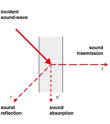
flections and undesirable background noise. In fact, the aim of an acoustic absorp-tion is to achieve an optimal value for reverberaabsorp-tion time depending on the type of environment and the activities that take place inside. Each material, in acoustic terms, is characterized by an absorption coefficient representing the relationship between the absorbed energy and the energy that strikes the material itself. When a sound-wave encounters a surface, three phenomena take place onto the inter-face between air and the surinter-face: a part of energy is absorbed by the material (α’), a part is reflected back in the air (r), the remaining part is transmitted through the material to the other side of the surface (t). According to the law of conservation of energy (3), the sum of the three coefficients that express the rate of incident sound energy that is absorbed (a’) reflected (r) and transmitted (t) is 1.
Figure 11. Sound-wave propagation.
The factors that influence this phenomenon are the surface’s material properties, its texture, and the relationship between the dimension of the surface patterning and the wavelength of the sound [68]. If, indeed, the object is much smaller than the wavelength, it is unable to interfere with the sound, that will propagate as if is it were not there; vice-versa when the obstacle is much bigger, the sound will reflect back in a specular manner; finally, if the wavelengths’ dimensions are comparable with the ones of the obstacle or surface’s roughness, that complex phenomenon of reflection, known as scattering, takes place [69]; but we will discuss about that (3) α’+ r + t = 1 sound trasmission α’ r t incident sound-wave sound
later, in the fifth chapter.
Although all materials, when stroked by a sound-wave, absorb, transmit and re-flect sound energy, they are commonly classified according to the predominant phenomenon that occurs as absorbing, reflecting or scattering materials.
Figure 12. Correlation between reflection phenomenon and absorbing materials.
During the last century, there has been great effort in exploring and studying sound absorptive materials, and in recent years several innovative absorptive solutions have been developed. On the contrary, the study of scattering and diffusers be-longs to a more recent period, over the past 20-30 years.
Nevertheless, both absorption and diffusion play significant roles in the acoustic design of spaces to reduce sound distortion. According to the primary function
absorption
acoustic treatment time response spatial response
reflection diffusion attenuated reflection -90° 90° -30° 30° -60° 60° 90° 60° 90° 60° 0° specular reflection -90° -30° 30° -60° 0° diffuse reflection -90° -30° 30° -60° 0°
to ensure acoustic quality. When sound energy plays a critical role, as concert halls, diffusers work best as they preserve the sound energy produced by the in-struments. Differently, whenever speech intelligibility is a concern, absorbers are employed to reduce the reverberation time and sound pressure level (SPL), while diffusers may be applied as well to ensure that early reflections would support the speech without creating distortions [68]. Although absorptive materials are able to minimize most of room effect over sounds, a high level of absorption can cause the space to be perceived as dead, so a balance use of diffusers and absorbers has to be preferred as it allows to control sound reflections while ensuring sound liveliness.
2.5.1. Absorbing materials
Absorbing materials are the primary technique to control the amount of reflected sound-waves, as they are able to dissipate a part of the sound energy of the inci-dent sound-wave into heat. This phenomenon can take place in several ways and depending on the materials it is effective in for some frequencies. As said above, absorbing material are used to control the reverberation time and SPL, but also to address distortion effects generated by sound reflections as echoes, flutter echoes and focusing effects, and to increase speech intelligibility. Nonetheless, an exces-sive amount of absorbing materials may lead to other undesirable effects, as a dry or dead perception of the space, so a balanced solution must be achieved [68]. In common practice, the parameter employed to describe the absorbing performance of a material is the sound absorption coefficient α (4). It defines the amount of sound energy that does not return to the space as reflected sound-wave, and thus, is either absorbed by the wall, or transmitted through the material.
The values may vary from 0 to 1; usually a material is considered sound-reflecting if α < 0.2, while if α > 0.5, it is considered sound absorbing. It is important to re-mark that the acoustic coefficient does not provide information about the amount of sound that is transmitted through the material. The sound absorption coefficient of materials is correlated with frequency, and it varies with different frequencies. The sound absorption coefficient frequency characteristic curves can be used to illustrate the sound absorption properties of different frequencies exactly.
The three main categories of sound-absorbing materials that have been used in (4) α’ + t = α
• porous absorbers; • resonant absorbers; • membrane absorbers.
Figure 13. Absorption curves for absorbent materials.
These materials have varying absorption coefficient across the spectrum range, and their efficiency may change according to the frequency of the incident sound. In general, porous materials are most efficient in higher frequencies but can have good performances also in middle and low frequencies. Differently, resonant and membrane absorbers are more effective with medium-low frequencies, with poor performances in the resting part of the spectrum [70]. To get broadband passive absorption across the frequencies of most interest to design, usually requires a combination of porous, resonant and membrane absorbers.
The following discusses these different sound absorbers explaining calculating formulae, employed in their acoustic design, that will be implement into the algo-rithm.
2.5.2. Porous absorbers
Porous materials are the most common and broadband types of absorbers: typical porous absorbers are carpets, acoustic tiles, acoustic (open cell) foams, curtains, cushions, cotton and mineral. They are categorized as cellular, fibrous or granular according to their micro-structure where sound propagation occurs in a network of interconnected pores in such a way that viscous and thermal effects cause acous-tic energy to be dissipated.
To enable these mechanisms, pores have to be inter-connected through the mate-porous absorber resonant absorber membrane absorber 1.0 0.9 0.8 0.7 0.6 0.5 0.4 0.3 0.2 0.1 0 63 125 250 500 1000 2000 4000 absorption coef ficient [-] frequency [Hz]
rial, and have openings on the material exposed surface, to enable the air flow to enter the material and dissipate its energy. When the incident sound-waves strikes the material, enters these interstices and is dissipated into heat through viscous effect. Given the fact that the porosity is the fraction of the total pore volume to the overall volume of the material; in general, the higher the porosity, the better the absorptivity. It must be noted that in the determination of porosity, closed pores should not be considered as they do not provide sound absorption [71].
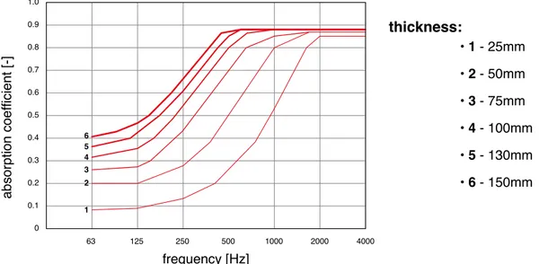
Porous materials are generally most effective at high frequencies: at lower fre-quencies, the absorptivity increases as the thickness of the material increases: Figure 14 shows the absorption coefficients for mineral wool absorbers illustrating the effect of material thickness; the porous absorber is mounted on a rigid backing.
Figure 14. Incidence of different thickness sound on the mineral wool absorbers’ absorption coefficient.
These curves follow the characteristic shape of porous absorption coefficients, a high pass filter response, although the curves can shift in frequency and move up and down in absorption depending on the characteristics of the material and how it is mounted. For low frequencies, where the wavelength is large, one must go a considerable distance from the wall to reach a point where the particle velocity is significant. This makes porous absorbers inefficient and not particularly useful at low frequency. Hence, a method to exploit this phenomenon without increasing the thickness of the material is to install the absorptive panel at a proper distance from the boundary surfaces, where air particles move at higher velocity : at least 1/10 of wavelength to provide significant absorption while at 1/4 wavelength provide maximum absorption [68]. 1.0 0.9 thickness: 0.8 0.7 0.6 0.5 0.4 0.3 • 1 - 25mm • 2 - 50mm • 3 - 75mm • 4 - 100mm • 5 - 130mm • 6 - 150mm 0.2 0.1 0 1 2 3 4 5 6 63 125 250 500 1000 2000 4000 absorption coef ficient [-] frequency [Hz]
A maximum absorption spectrum can be achieve through design of the minimum frequency the following equations [70]:
where
c is the speed of sound in air, c = 343 m/s at 20°C; λmax is the wavelength of maximum absorption, in m; d is the material thickness, in m;
d’ is the distance between the material and the rigid backing, in m.
Finally, as porous absorbers are generally prone to damage, they are protected thought the use of acoustical transparent device that also improve their visual appearance. These are facings such as, thin membrane (<2 mm) wrapped around the panel, or perforated panels with a structure opened enough (30%-50%) not to impede the propagation of sound-waves through it [68].
2.5.3. Resonant absorbers
In order to ensure absorption for lower frequencies, resonant absorbers are usu-ally preferred since their dimensions are more compact than porous absorbers. Furthermore, treatments are often placed at room boundaries where porous ab-sorbers are inefficient as the particle velocity is low. By exploiting resonance, it is possible to get absorption at low to mid-frequencies. The absorption characteris-tics of these resonant devices are a peak of absorption. Unlike porous materials, wide band absorption is difficult to achieve in such devices, resonant absorbers offer a high rate of absorption within a limited range of frequencies [72]. So, one of the frequent challenges in the design of resonant structures is to extend the bandwidth. A typical resonant device is the Helmholtz absorber, which is named after the German physician and physicist Hermann von Helmholtz (1821–94). In (6) (5) effective ineffective λ/4 vmax v d’ d vmax v d’=0 d
the case of a Helmholtz absorber, the mass is a plug of air in the opening of the perforated sheet. The resonance is produced by the same mechanism which gen-erates a note when you blow across a beer bottle. It is rarely used in the classroom acoustics but absorbing panels that use its physical principle have been construct-ed by perforating, milling or punching hole-openings in panels: the assumption is that the hole spacing should be large in comparison to hole diameter. The result-ing panel works as a multiple Helmholtz resonator, in which the small openresult-ings are the necks, and the air gap behind the panel is the cavity. Absorbers like these, come in a great variety of materials, finishes and form, and thus, are greatly em-ployed in architectural projects. In fact, they play a crucial role in controlling SPL, reverberation time and addressing issues occurring at low frequencies, as room modes.
Resonant absorbers function as a mass vibrating against a spring and provide maximum absorption around their resonant frequency: therefore, by changing the mass and the stiffness of the spring, it is possible to tune these devices to make them effective at a frequency of interest. If wider bandwidth of absorption is re-quired it is possible to apply porous absorption in the cavity of resonant absorb-ers. Under the assumption that the panel thickness and the hole radius are much smaller than the acoustic wavelength, the resonant frequency of the overall panel can be determined with the following equation [70]:
where
c is the speed of sound in air, c = 343 m/s at 20 °C; ρ is the drilling percentage;
D is the cavity depth, in m; h is panel thickness, in m.
By reducing the number of openings, the peak absorption of the panel will
de-v
h D
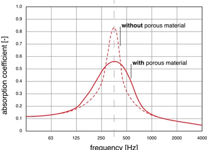
crease in frequency and the bandwidth over which it is effective will be shortened. However, decreasing the resonant frequency, may reduce the peak absorption co-efficient, lowering the efficiency of the device. Under the constraints of maintaining the same overall thickness of panel and cavity, the resonant frequency would de-crease for growing thickness of the panel. To improve the absorption of the system it is possible to place a layer of porous material in the cavity, close to the neck, or even directly in the openings, where the air velocity is maximum, in order to pro-vide dampening [68, 72]. A method to increase the absorption of perforated panels of oblique-incidence sound-waves at low frequencies, it is to physically subdivide the cavity in single volumes, this way reducing the lateral propagation within the air gap. In case, instead, a layer of porous absorptive is present in the cavity, the physical subdivision is a lower requirement.
Figure 15. Absorption curve of an acoustic resonator as a function of frequency, with and without porous material inside the air cavity.
2.5.4. Membrane absorbers
Membrane absorbers are also mass-spring systems, this time however the vi-brating mass is a flexible membrane or plate and the spring is air in the cavity between the membrane and the reflective surface. When a sound-wave strikes the membrane, it is set into motion: the vibration alternately compress the air com-prises in the cavity and part of the sound energy is dissipated into heat: smaller depth generates higher resistance and moves the absorptive bandwidth to upper frequencies.
Their employment in architectural spaces is due by the great variety of materials
1.0 0.9 0.8 0.7 0.6 0.5 0.4 0.3 0.2 0.1 0 63 125 250 500 1000 2000 4000 absorption coef ficient [-] frequency [Hz]
with porous material without porous material
that can be used as panels. However, a small size of the panel can compromise the ability of the panel to vibrate freely since it must be fixed at the edges, reduc-ing the effective mass vibratreduc-ing: hence, panels should be at least 0.5 m2; in case
of smaller membrane, a resilient fixing should allow the whole plate to vibrate, solving this issue [68, 72]. Similar to Helmholtz resonators, they provide only nar-row band absorption, in most cases is below 400Hz, and the peak of absorption is reached at the resonant frequency of the system.
The resonant frequency of this system can be found [70]:
where
M is material surface mass, in kg/m2;
d is the air-gap depth, in m;
ρ is the material density, in kg/m3;
s is panel thickness, in m.
This formula provides a useful first approximation but often yield inaccurate re-sults with errors of up to 10 per cent because, unlike Helmholtz absorbers, the prediction of the behaviour of membrane absorbers is difficult as the exact mount-ing conditions and properties of the membrane are hard to predict and model. The bandwidth can be increased by increasing the damping, but as with any mass-spring system, this has the effect of decreasing the maximum efficiency of the absorber. Again, the installation of porous absorbers within the air cavity would increase the performances of the device by extending the frequency range of operation, exploiting the velocity of the air particles within the cavity that are set into motion by the membrane. In this case the layer of porous absorbers should be placed behind the membrane, ensuring that they are not in contact [68, 71]. A trade off therefore ensues between bandwidth and maximum absorption.
d s L ρ (8) (9)
Figure 16. Absorption curve of a membrane absorber as a function of frequency with and without porous material in the air cavity.
1.0 0.9 0.8 0.7 0.6 0.5 0.4 0.3 0.2 0.1 0 125 250 500 1000 2000 4000 absorption coef ficient [-] frequency [Hz] with porous material without porous material
3. UNI 11532 STANDARD
Poor acoustic quality is common in the Italian educational panorama. Although there are standards stating acoustic requirements that should be met in class-rooms or other educational spaces, it is too often not observed.
As in other countries, also in Italy, there is a lack of acoustic expertise in archi-tects, engineers, school principals, teachers and student’s education.
The new Italian UNI11532 standard returns to the North-European legislation, for a long time most up-to-date in this field [22]. It is a review of the UNI11532-2014; at the time of writing, it is composed by two parts: the first is in force since March 2018, the latter currently in public consultation and ready to be published.
The new developments regard the introduction of new aspects relating to acous-tic comfort and the noise within the measurement environment, generated by the equipment for example. The standard addresses architects, building designers, building owners, and specialist engineers who are involved in the planning, con-struction and renovation of rooms covered by this standard. However, the latter still needs to be investigated.
The purpose and fields of application, calculating formulas and the reference val-ues of the acoustic parameters that will be implement in the algorithm described in the fourth chapter, will be presented below. Finally, an overview on the spatial distribution of sound-absorptive and sound-reflecting surfaces in classroom envi-ronments will be given. For all the rest, see the full-text of the standard.
3.1. Purpose and scope of the standard
The first part of the standard describes the general common aspects of different application sectors, as well as, defines the descriptors that represent the acoustic quality of an environment in relation to the intended use of the environment itself [73].
Based on the defined descriptors, it recommends evaluating methods and verifi-cation techniques. The standard applies to environments with different uses in the following sectors:
• school sector: communicative / collective, small conference; • health sector;
• catering sector; • service sector; • sports sector;
• museum sector: fair, exhibition.
The standard does not cover the acoustic quality of rooms with special require-ments, such as theatres, concert halls, cinemas, sacred spaces, or in rooms for the high-quality recording of music and speech (e.g. studios, central control rooms for radio, film, television and sound storage media productions). However, this standard can be applied by analogy to rooms for general musical presentations, multi-purpose rooms.
The UNI11532-2 takes up the room acoustic parameters defined in the first part providing the target values for the school sector and all other uses related to it, both in relation to the intended use of the environment and considering people with hearing impairment, concentration, non-native speakers or with language dif-ferences or with different needs.
In the educational environments, the understanding of speech is a primary impor-tance requirement, for which many determinant factors are considered, such as: • soundproofing to airborne and impact noise between different environments to
avoid mutual interaction between spaces;
• sound insulation from outside in order to avoid excessive residual noise;
• the noise level of fixed installations for use by the structure and individual rooms;
• the reverberation of the room; • the intelligibility of speech. 3.2. Evaluating method 3.2.1. Reverberation Time
The evaluating method recommended for calculating the reverberation time is
de-scribed by UNI EN 12354-6 [74]. It is essentially the Sabine formula as expressed in (1) which take into account the acoustic air absorption.
3.2.2. Speech Clarity
The Speech Clarity C50 can be determined in an approximate way with the formu-la (10) or in a precise way with the formuformu-la (11), in dB, according the Barron & Lee revised theory [75]:
where
T is the reverberation time, in s;
where
V is the total room volume, in m3;
T is the reverberation time, in s;
r is the distance of the source from the receiver, in m. 3.2.3. Speech Transmission Index
The measurement method of STI, including the limitations of applying the two pa-rameters, is described in IEC 60268-16 [67].
3.2.4. Overall noise in the environment
Two factors affecting the prediction of STI values are both the noise that occur in the room with not-operating plants, and linked to the environmental context in which the building is located, L2, and the noise of the room equipment, Lic,int. The noise level inside the room Lamb is the energetic sum of both contributions, it is ex-pressed as the spatial energy average of the values obtained in the user positions indicated in Figure 17.
The residual noise level in the room, in octave bands from 125 Hz to 4 kHz, is obtained for the different positions shown in Figure 17, starting from the average sound pressure levels in the internal environment due to external noise, L2, in oc-tave bands from 125 Hz to 4 kHz, in according to the formula:
(10)
L2 = L1,2m-D2m,nT +10log(T/T0) [dB] where
L1,2m is the sound pressure level outside the building, at a distance of 2 m from the facade, in dB;
D2m,nT is the façade sound insulation standardized to the reverberation time, in
dB;
T is the reverberation time, in s;
T0 is the reverberation time reference value, it is equal to 0,5 s for all octave bands in s.
Since L1,2m is considered at a distance of 2m from the façade, if the external sound pressure level refers to the incident noise without considering the building, or ante operam, L1,2m must be increased by 3 dB for all frequency bands considering the reflection on the facade. The noise level of the equipment inside the room is ex-pressed through the Lic,int descriptor, obtained from the spatial energy average of the Lpu,c values in the user positions as specified in Figure 17.
Lpu,c= LAeq - K1 + K2 [dB(A)] where
LAeq is the equivalent continuous sound level, measured with operating systems, in dB(A);
K1 is the noise correction term measured with not-operating systems, in dB; K2 is the standardized term to the reverberation time.
If the difference between the sound pressure level of the noise induced by the systems and the residual noise level Lr is between 4 dB(A) and 10 dB(A) the cor-rection term is calculated using the following relations:
K1 = – 10log(1 – 10–ΔL/10) ΔL = LAeq – Lr (12) (13) (14) (15) where
Lr is the equivalent continuous sound level, measured with system not in op-eration in dB(A);
If ΔL is less than or equal to 4 dB(A) the correction term K1 is equal to 2,2 dB. K2 = – 10log(T/T0)
where
T is the arithmetic average of the reverberation times measured in the octave bands between 125 Hz and 4 kHz, measured in the user positions in the environ-ment, in s;
T0 is the reverberation time reference value depending on the volume, in s (Table 03).
Table 03. Reverberation time reference value depending on the volume.
3.3. Target values
In order to define the objectives to be pursued, it is fundamental:
• to determine the primary use of the environment according to the categories identified in Table 04.
Table 04. Rooms categories in relation to the primary use.
(16)
volume reverberation time reference
V ≤ 100 m3 T 0 = 0.5 s 100 < V < 2500 m3 T 0 = 0.05·V·0.5 s V ≥ 2500 m3 T 0 = 2.5 s
category room primary use
A1 music
A2 speech/conference
A3 teaching, teacher-pupil interaction
A4 lecture/ communication, special classrooms
A5 sport