Alma Mater Studiorum · Universit`
a di Bologna
Scuola di Scienze
Dipartimento di Fisica e Astronomia Corso di Laurea Magistrale in Fisica
Big Data Analytics towards Predictive
Maintenance at the INFN-CNAF
computing centre
Relatore:
Prof. Daniele Bonacorsi
Correlatore:
Dott.ssa Barbara Martelli
Presentata da:
Simone Rossi Tisbeni
Abstract
La Fisica delle Alte Energie (HEP) `e da lungo tra i precursori nel gestire e proces-sare enormi dataset scientifici e nell’operare alcuni tra i pi`u grandi data centre per applicazioni scientifiche. HEP ha sviluppato una griglia computazionale (Grid) per il calcolo al Large Hadron Collider (LHC) del CERN di Ginevra, che attualmente coordina giornalmente le operazioni di calcolo su oltre 800k processori in 170 centri di calcolo e gestendo mezzo Exabyte di dati su disco distribuito in 5 continenti.
Nelle prossime fasi di LHC, soprattutto in vista di Run-4, il quantitativo di dati gestiti dai centri di calcolo aumenter`a notevolmente. In questo contesto, la HEP Software Foundation ha redatto un Community White Paper (CWP) che indica il percorso da seguire nell’evoluzione del software moderno e dei modelli di calcolo in preparazione alla fase cosiddetta di High Luminosity di LHC. Questo lavoro ha individuato in tecniche di Big Data Analytics un enorme potenziale per affrontare le sfide future di HEP.
Uno degli sviluppi riguarda la cosiddetta Operation Intelligence, ovvero la ri-cerca di un aumento nel livello di automazione all’interno dei workflow. Questo genere di approcci potrebbe portare al passaggio da un sistema di manutenzione reattiva ad uno, pi`u evoluto, di manutenzione predittiva o addirittura prescrittiva. La tesi presenta il lavoro fatto in collaborazione con il centro di calcolo dell’INFN-CNAF per introdurre un sistema di ingestione, organizzazione e processing dei log del centro su una piattaforma di Big Data Analytics unificata, al fine di prototipiz-zare un modello di manutenzione predittiva per il centro. Questa tesi contribuisce a tale progetto con lo sviluppo di un algoritmo di clustering dei messaggi di log ba-sato su misure di similarit`a tra campi testuali, per superare il limite connesso alla verbosit`a ed eterogeneit`a dei log raccolti dai vari servizi operativi 24/7 al centro.
Contents
Introduction 1
I
Big Data Analytics on WLCG Tiers
5
1 HEP Computing evolution and Big Data Analytics 7
1.1 Computing in HEP in the next decades . . . 7
1.2 Big Data Analytics . . . 9
1.3 Machine Learning in HEP and at LHC . . . 13
1.4 The raise of operation intelligence . . . 14
2 LHC Computing Tiers 17 2.1 The WLCG project . . . 17
2.2 Tiers in the Grid . . . 18
2.3 The INFN-CNAF Tier-1 . . . 20
2.3.1 Farming . . . 21
2.3.2 Storage . . . 21
2.3.3 Networking . . . 22
3 Overview of maintenance strategies 25 3.1 Maintenance classification . . . 26
3.2 Reactive Maintenance . . . 26
3.3 Preventive Maintenance . . . 28
3.3.1 Planned Preventive Maintenance . . . 28
3.4 Predictive Maintenance . . . 29
3.4.1 Log-based Predictive Maintenance . . . 30
3.5 Prescriptive Maintenance . . . 32
II
Towards predictive maintenance at CNAF
35
4 Logging data at CNAF 37 4.1 Metrics and Logs . . . 374.1.1 Rsyslog . . . 38 4.1.2 InfluxDB . . . 38 4.2 Log Repository . . . 39 4.3 StoRM logs . . . 41 4.3.1 Frontend server . . . 41 4.3.2 Backend server . . . 43 5 Infrastructure setup 45 5.1 DODAS . . . 47 5.2 Hadoop-HDFS-Yarn . . . 48 5.3 Flume-Kafka . . . 49 5.4 Spark . . . 50
6 Log files analytics 53 6.1 Preliminary investigation of CNAF log files . . . 54
6.1.1 Log ingestion and visualisation . . . 54
6.1.2 Log parsing and structuring . . . 55
6.1.3 Log features extraction with ML . . . 57
6.2 Case study: text-based log clustering . . . 58
6.2.1 Log anonymisation . . . 60
6.2.2 Comparison of similarity measures . . . 60
6.2.3 Time complexity . . . 65
6.2.4 Levenshtein similarity threshold . . . 68
6.3 Backend log clustering . . . 78 6.3.1 Results . . . 78 6.4 Future developments . . . 82 Conclusion 87
Appendices
91
A Frontend plots 91 B Backend plots 103 Bibliography 118List of Figures
1.1 Upgrade schedule for the LHC/HL-LHC. Shutdown periods and data-taking periods, each with its intended instantaneous luminos-ity and centre-of-mass energy, are shown [1]. . . 8 1.2 Infographic break down of the 4 Vs, as defined by IBM data
scien-tists: volume, variety, velocity and veracity. For higher resolution see [6]. . . 11 1.3 Processes for extracting insights from big data as defined by [4]. . . 12 2.1 Schematic representation of the Tier levels, as defined by the MONARC
model [21]. See text for details. . . 19 3.1 Timeline of maintenance generations [28]. See text for details. . . . 27 3.2 Stage model for characterising data analytics use cases [40]. . . 32 4.1 Total size of the log files stored into the Log Repository as a function
of time. . . 40 4.2 Simple StoRM Service Architecture schema with one Backend and
one Frontend. . . 42 5.1 Schematic representation of the unified monitoring system in use at
CERN [47]. . . 46 5.2 Schematic representation of the distributed log ingestion and
anal-ysis platform being implemented at CNAF. . . 47 6.1 Fuzzy string search in a common web search engine. . . 63
6.2 Number of clusters as a function of lines per log, in FE server log (02/12/2018) with similarity threshold = 0.7. . . 66 6.3 Number of log lines parsed as a function of the running time, and
the matching fit line for FE server log (02/12/2018). The markers correspond to the creation of a new cluster. . . 67 6.4 Close up of Figure 6.3 for the first seconds of runtime. The markers
correspond to the creation of a new cluster. . . 68 6.5 Number of log lines clustered as a function of the running time for
the FE server log (02/12/2018). The slope of the curve decreases for higher similarity thresholds. . . 69 6.6 Mean in-cluster variance as a function of the similarity threshold
and the corresponding number of cluster for the FE server log (02/12/2018). . . 70 6.7 Mean cluster variance at different similarity levels for the entire log
file (p100) for the 95th percentile (p95) for the 90th percentile (p90) and the 80th percentile (p80) for the FE server log (02/12/2018). . 72 6.8 Clusters population for FE server log file (02/12/2018), with
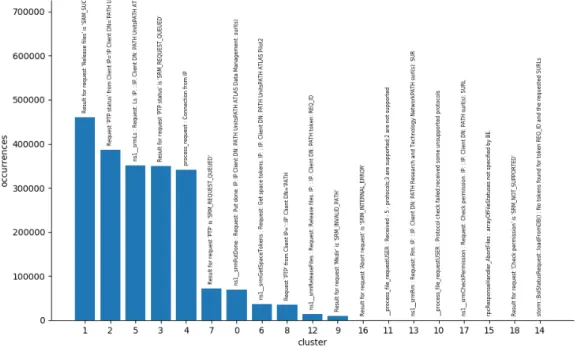
similar-ity threshold 0.675. Every bar is labelled with the cluster’s reference message. . . 73 6.9 Clusters population for FE server log file (02/12/2018) with
simi-larity threshold 0.675, in logarithmic scale. Details in the text. . . . 75 6.10 Clusters population for FE server log file (02/12/2018), with
simi-larity threshold 0.7. Every bar is labelled with the cluster’s reference message. . . 77 6.11 Clusters population for a random sample of 90% of the FE server
log file (02/12/2018), with similarity threshold 0.7. Every bar is labelled with the cluster’s reference message. . . 77 6.12 Clusters population for BE server critical log file (23/05/2019), with
similarity threshold 0.65. Every bar is labelled with the cluster’s reference message. . . 79
6.13 Clusters population for BE server critical log file (23/05/2019) with similarity threshold 0.6, in logarithmic scale. Details in the text. . . 80 6.14 Log messages at time of logging, visualised after the cluster creation
process. The y-axis refers to the clusters id generated by the cluster creation algorithm. The x-axis is the time. Every dot in the graph represents an actual message from the log, showing its mapping to one of the discovered clusters. . . 83 6.15 Correlation between clusters created from two different log days
measured as the similarity between their reference message. Lighter red shades for similarities lower than the threshold of 0.675, darker greens for similarities higher than the threshold. . . 84 A.1 Mean variance in clusters for Jaccard similarity applied on a sample
file of 20000 lines from FE. . . 91 A.2 Mean variance in clusters for Cosine similarity applied on a sample
file of 20000 lines from FE. . . 92 A.3 Mean variance in clusters for Levenshtein similarity applied on a
sample file of 20000 lines from FE. . . 93 A.4 Number of clusters as a function of lines per log, in FE server log
(06/12/2018) with similarity threshold = 0.7. . . 94 A.5 Number of log lines clustered as a function of the running time for
the FE server log (06/12/2018). The slope of the curve decreases for higher similarity threshold. . . 95 A.6 Number of clusters as a function of lines per log, in FE server log
(07/12/2018) with similarity threshold = 0.7. . . 96 A.7 Number of log lines clustered as a function of the running time for
the FE server log (07/12/2018). The slope of the curve decreases for higher similarity threshold. . . 96 A.8 Mean cluster variance at different similarity levels for the entire log
file (p100) for the 95th percentile (p95) for the 90th percentile (p90) and the 80th percentile (p80) from the FE server log (06/12/2018). 97
A.9 Mean cluster variance at different similarity levels for the entire log file (p100) and for lower percentiles (p80, p90, p95) from the FE server log (07/12/2018). . . 98 A.10 Clusters population for a second random sample of 90% of the FE
log file (02/12/2018), with similarity threshold 0.7. . . 98 A.11 Clusters population for a third random sample of 90% of the FE log
file (02/12/2018), with similarity threshold 0.7. . . 99 A.12 Clusters population for FE server log file (06/12/2018), with
similar-ity threshold 0.675. Every bar is labelled with the cluster’s reference message. . . 99 A.13 Clusters population for FE server log file (07/12/2018), with
similar-ity threshold 0.675. Every bar is labelled with the cluster’s reference message. . . 100 B.1 Number of log lines clustered as a function of the running time for
the BE server log (25/05/2019). The slope of the curve decreases for higher similarity thresholds. . . 103 B.2 Mean cluster variance at different similarity levels for the entire log
file (p100) for the 95th percentile (p95) for the 90th percentile (p90) and the 80th percentile (p80) from the BE server log (25/05/2019) . 104 B.3 Clusters population for BE log file (22/05/2019), with similarity
threshold 0.6. . . 105 B.4 Clusters population for BE log file (22/05/2019), with similarity
threshold 0.6. Y-axis in logarithmic scale to highlight the least populated clusters. . . 105 B.5 Clusters population for BE log file (24/05/2019), with similarity
threshold 0.6. . . 106 B.6 Clusters population for BE log file (24/05/2019), with similarity
threshold 0.6. Y-axis in logarithmic scale to highlight the least populated clusters. . . 106 B.7 Clusters population for BE log file (25/05/2019), with similarity
B.8 Clusters population for BE log file (25/05/2019), with similarity threshold 0.6. Y-axis in logarithmic scale to highlight the least populated clusters. . . 107 B.9 Clusters population for BE log file (26/05/2019), with similarity
threshold 0.6. . . 108 B.10 Clusters population for BE log file (26/05/2019), with similarity
threshold 0.6. Y-axis in logarithmic scale to highlight the least populated clusters. . . 108 B.11 Clusters population for BE log file (27/05/2019), with similarity
threshold 0.6. . . 109 B.12 Clusters population for BE log file (27/05/2019), with similarity
threshold 0.6. Y-axis in logarithmic scale to highlight the least populated clusters. . . 109 B.13 Clusters population for BE log file (28/05/2019), with similarity
threshold 0.6. . . 110 B.14 Clusters population for BE log file (28/05/2019), with similarity
threshold 0.6. Y-axis in logarithmic scale to highlight the least populated clusters. . . 110
List of Tables
4.1 Sample directory structure for the Log Repository. Details in the
text. . . 39
4.2 Sample log line from storm-frontend-server.log from 8/12/2018. . . 42
4.3 Sample of log line from storm-backend-server.log from 8/12/2018. . 43
4.4 Sample of log line from storm-backend-metrics.log from the 8/12/2018. 43 6.1 Log line from storm-backend-metrics.log with fields replaced by identifiers. . . 55
6.2 Truncated storm-backend-metrics parsed .csv file. . . 56
6.3 Four sample lines from storm-frontend-server.log. . . 56
6.4 Sample of a truncated storm-frontend-server.csv file. . . 57
6.5 Pseudocode of the log clustering algorithm. Details in the text. . . 59
6.6 Sample log messages with highlighted fields to be masked. . . 60
6.7 Sample log messages with masked fields. . . 60
6.8 Comparison of the results between different similarity measure ap-plied on sample sentences. . . 64
6.9 Total number of clusters and slope of the fit line for the evalua-tion time of the FE server log (02/12/2018) at different similarity thresholds. . . 69
6.10 Cluster population and reference message for FE server log file (02/12/2018) with similarity threshold 0.675. . . 74
6.11 File size of the log files from StoRM CMS’s BE in the week from 22/05/2019 to 28/05/2019. The highlighted row marks the critical day. Details in the text. . . 81
A.1 Number of clusters and iteration per second for Jaccard similarity with different similarity thresholds on sample file of 20000 lines from FE. . . 92 A.2 Number of clusters and iteration per second for Cosine similarity
with different similarity thresholds on sample file of 20000 lines from FE. . . 92 A.3 Number of clusters and iteration per second for Levenshtein
simi-larity with different simisimi-larity thresholds on sample file of 20000 lines from FE. . . 93 A.4 Total number of clusters and slope of the fit line for the
evalua-tion time of the FE server log (06/12/2018) at different similarity threshold. . . 95 A.5 Total number of clusters and slope of the fit line for the
evalua-tion time of the FE server log (07/12/2018) at different similarity thresholds. . . 97 A.6 Cluster population and reference log for FE server log file (06/12/2018)
with similarity threshold 0.675. . . 100 A.7 Cluster population and reference log for FE server log file (07/12/2018)
Introduction
High Energy Physics (HEP) has been a driver in managing and processing enor-mous scientific datasets and the largest scale high throughput computing cen-ters. Part of the HEP community developed a large scientific computing Grid for the Large Hadron Collider (LHC) at CERN in Geneva, that nowadays regularly overview the operations of 800k computer cores from over 170 sites in 42 countries, and half of an exabyte of disk storage distributed on 5 continents.
With the upcoming start of Run-3, and especially Run-4, the amount of data managed by the Tiers centres is expected to massively increase. In this view, the HEP Software Foundation — that published a Community White Paper providing a roadmap for the future research in software and computing in preparation for the HL-LHC — highlighted the enormous potential advantages that might come from applying Big Data Analytics techniques in the LHC physics endeavour.
One of the advancements discussed in that context is in Operations Intelligence in computing systems. A team effort has recently been promoted by a group of HEP computing teams, and one of the goals is to explore the logging data and apply data mining and analytics approaches to extract actionable insight and hence increase the level of automation in various systems. This effort, once applied to computing centers, may result into stepping out of Reactive maintenance to a Predictive or even Prescriptive approach.
This thesis will present the preliminary steps taken to introduce a unified Log ingestion and analytics platform at the INFN-CNAF Tier-1 across its services, with the purpose of exploring possible solutions for the development of a Predic-tive Maintenance model to detect and anticipate failures. This thesis explores the
design and deployment of such an infrastructure as well as the development of proper algorithms to extract insight from log data.
This dissertation is divided in two parts: in Part I this work is contextualised, introducing the evolution in HEP, the structure of WLCG and discussing the concept of maintenance. Part II, instead, will focus on the exploratory work started at INFN-CNAF Tier-1 in the last year revolving around the analysis of the log data of the centre and their possible use to define a Predictive Maintenance model to apply in the future.
In particular, Chapter 1 will discuss the upgrade schedule of LHC and the plan defined by the HSF to prepare for the future improvements in software and computing. The main concepts of Big Data, Analytics and Machine Learning will be briefly presented as well as an overview of the interest of LHC experiments in these fields.
Chapter 2 will focus on the WLC Grid, presenting the various tiers and later focusing on the INFN-CNAF Tier-1; the structure of the computing centre will be discussed, highlighting the main challenges as a major WLCG Tier-1.
Chapter 3 will close Part I, and will offer an overview on the different Main-tenance classes, reviewing their characteristics and use cases; some examples of effective use of various maintenance models in data centres will be briefly pre-sented, concluding with a description of most advanced Prescriptive Maintenance models.
Chapter 4 will open Part II by showcasing the types of data logged at INFN-CNAF; it will present the recent developments of a Log Repository solution to unify and collect all the log sources of the data centre; it will also include an overview about the log files from StoRM that will be analysed in the last chapter. Chapter 5 focuses on the set up of a first Log ingestion and processing dis-tributed platform to analyse the data stored in the Log Repository; the chapter also includes a brief description of the open source technical components used to design and deploy the platform.
clus-tering in an unsupervised way the verbose event log files from StoRM, using text-based similarity measures. The Chapter will begin by discussing the previous work done during the CNAF Summer School program, it will then follow the develop-ment of the log clustering algorithm discussing the choice of similarity measure and the parameters that can influence the results. The developed procedure will be tested on different log files and the results compared to highlight their ability to detect possible anomalous behaviours. The concluding section in the chapter will focus on future developments of this work.
Part I
Big Data Analytics on WLCG
Tiers
Chapter 1
HEP Computing evolution and
Big Data Analytics
1.1
Computing in HEP in the next decades
In the long path that will bring the existing LHC systems towards new life in the High Luminosity regime, several technical upgrades are envisaged in the course of the next few years. The upgrade plans towards the HL-LHC are pictorially depicted in Figure 1.1.
The LHC is currently in its Long Shutdown 2 (LS2), scheduled to last until 2020 included, and in which experts are busy on the Phase-I upgrade of the LHC injectors, with aim of reaching the 14 TeV centre-of-mass energy and increasing the instantaneous luminosity by a factor of 3, for the start of the Run-3 data taking period. Subsequently, the Phase-II upgrade will take place between 2024 and 2026, and will eventually complete the increase in luminosity, yielding to HL-LHC with a peak luminosity of about L = 7 × 1034cm−2s−1. An integrated luminosity of
250f b−1 per year will be made possible thanks to the installation of new elements including new focusing magnets and crab cavities. In the final luminosity scenario, the expected mean number of 200 interactions per bunch crossing will be reached. Such a large and wide scope project requires large investments also in the R&D of software and computing systems needed to acquire, manage, process,
Figure 1.1: Upgrade schedule for the LHC/HL-LHC. Shutdown periods and data-taking periods, each with its intended instantaneous luminosity and centre-of-mass energy, are shown [1].
and analyse the huge amount of data that will be recorded. In fact, despite the programme evidently requires investments in detector hardware - both to build new facilities or experiments, and to upgrade existing ones - it is also true (and often mistakenly underestimated) that a commensurate financing effort is needed on software and computing in order to efficiently and successfully exploit the future facilities.
In this view, the HEP Software Foundation (HSF) [2] made a planning exercise in 2016 and published a Community White Paper (CWP) [3]. The document provides a roadmap for software and computing R&D in preparation for the HL-LHC and for other HEP experiments on a similar timescale: it clearly identifies areas of work and priorities in the investments. Quoting from [3], these priorities are:
• to achieve improvements in software efficiency, in its scalability and perfor-mance, and make use of all possible advances in CPU, storage and network technologies in order to cope with the challenges in front of the HEP com-munity;
• to enable new approaches to software and computing that could radically extend the physics reach of the upgraded detectors;
• to ensure the long-term sustainability of the software through the entire lifetime of the HL-LHC;
• to ensure data (and knowledge) preservation beyond the specific lifetime of each individual experiment;
• to attract the required new expertise by offering appropriate career recogni-tion to physicists that specialise in software development and/or computing systems design and development, and by effective training efforts able to target all software-level contributors in the community.
A description of the activities that started already and will bring the LHC community to stage that will ensure that software and computing will still be -as they have been in Run-1 and Run-2 - an enabling technology for HL-HLC, will bring us far out of the scope of this thesis. In this thesis, instead, a focus will be maintained on two specific aspects of this vast community effort, namely the effectiveness of Big Data Analytics and the raise of Machine Learning and Deep Learning.
1.2
Big Data Analytics
Big Data (BD) nowadays is a widespread term, defining almost any type of data analysis and statistics performed on large amount of data, but most of the time is used as a buzzword with almost no relation to the original meaning.
Gandomi et al. [4] follow the definition of BD back to sparse references in the mid-nineties through its widespread use since 2011, and suggests that as low as 4 different definitions are mainly used in the industry to understand BD.
The current widespread use of the term can be attributed to the promotional initiatives of IBM that also brought to the mass public attention the concept of the “five Vs”. First defined by [5], the original definition described BD by just three characteristics that elaborate on the dimensions of challenges in data management.
• Volume - Refers to the magnitude of data, reported in multiple terabytes or even petabytes. The definition of BD volumes is not strict since it strictly correlates to Variety: two datasets of the same size may require different magnitude of work if one of them is strictly numerical values, while the other are structured objects.
• Variety - Refers to the structural heterogeneity in a dataset. Structured data refers to the tabular data found in databases while unstructured data are for example raw images, text, numerical values etc. A characteristic of BD is the high level of variety between structured and unstructured data and their content.
• Velocity - Velocity refers to the rate at which data are generated and the speed at which it should be analysed and acted upon. Traditional data analysis systems are not able to handle fast flowing data streams, while BD technologies should be developed to ingest large amount of data quickly. An additional term is commonly used, after IBM coined it in [6]:
• Veracity - Represents the unreliability inherent in some sources of data. Another big factor in defining BD is the need to deal with imprecise and uncertain data, often derived from human subjectivity and lack of standards. This situation is usually managed through the use of data mining and fuzzy matching.
More recently Oracle [7] introduced a new term as a defining attribute of BD: • Value - Refers to the ability to extract value from the data. The assumption is that the value density in BD is low, since the information is spread into an higher volume of data.
Based on these definition, the data source from LHC respect the concept of Variety, Volume and Velocity; it is harder to find correspondence for the other Vs, the output data from the experiment is strictly structured and follow a defined
Figure 1.2: Infographic break down of the 4 Vs, as defined by IBM data scientists: volume, variety, velocity and veracity. For higher resolution see [6].
pattern that is not subject to Veracity and most of the information is relevant with high Value density.
With the definition of Big data often comes the term Big Data Analytics (BDA). BDA encompasses the process of decision making and analysis that extract value from BD. The overall process can be broken down into the five stages shown in Figure 1.3. These five stages are divided into two processes: data management and analytics. Data management involves processes and supporting technologies to acquire the data, store it in a structured database, and prepare it for analysis by extracting the relevant features, cleaning the data and integrating the miss-ing values. Analytics, on the other hand, refers to techniques used to analyse and interpret the information from BD; this process can either involve data min-ing techniques, classical statistical methods or the more recent Machine Learnmin-ing approaches.
The application of BDA of interest in this thesis is related to LHC experi-ments at CERN. As it will be discussed and introduced in Chapter 2, LHC is a
Figure 1.3: Processes for extracting insights from big data as defined by [4].
major worldwide scientific enterprises, one of the largest and most complicated pieces of experimental apparatus that were ever constructed. At the same time, the LHC experiments are enormous, extremely complicated detectors that are able to extract physics information from proton-proton and heavy-ion collisions at ex-ploiting the most advanced detecting techniques existing nowadays. In addition, the overall data handling and processing relies on a scientific computing Grid that now regularly operates O(1M ) processor cores and half of an exabyte (EB) [8] of disk storage located on 5 continents through hundreds of connected comput-ing facilities, and orchestratcomput-ing all this through a large set of different software services.
This extreme complexity, at various levels, is concretely able to eventually produce physics results via the capability to manage -in a wide sense - extremely large volumes of data.
The application of BD techniques in the LHC physics endeavour is hence cru-cial. At the same time, such application is different in face of a very diverse variety of existing LHC data. The data produced at LHC is of different types, e.g. original collisions data (coming from particle collisions), non-collisions data (e.g. alignment and calibration data), simulation data (coming from Monte Carlo techniques), de-rived data (coming from users’ manipulation of original data through selections, skimming, reconstructions, etc), and various type of additional data like logging data (data coming from messages of running systems and servers) and meta-data (namely, data that contains information on the data itself).
In this thesis, the focus is on the application of BDA techniques on logging data coming from services running at the INFN-CNAF computing centre. While this might seem a limitation to a relatively small subset of LHC BD, a few numbers should suffice to clarify that actually this is indeed a subset, but its size is far from being small and easy to manage.
The CNAF centre hosts of the orders of O(100) different services of various complexity. Some consist of just one machine, and some other of dozens or hun-dreds of different nodes. Each node/machine regularly prompts a log with most relevant operational messages. To give an example - as it will be described in more details in Chapter 4 - the machines that are currently logging and whose log data are being kept into the BD infrastructure described in this thesis are a total of 1130; each one archives several types of logs, on average around 17 different log files; the size of each log ranges from few MBs to tens of GB; all this logging hap-pens daily: a rough count gives an average of 12 GBs of logs daily, for an estimate of 4 to 5 TB of data each year.
The work presented in Part 2 of this thesis will focus on the development of a BDA framework to ingest this type of data, and the development of an exper-imental algorithm for extracting information from the log files, this falls into the Data Management process of BDA described above; future development would likely involve a dive into Analytics tool, possible with the aid of Machine Learning approaches.
1.3
Machine Learning in HEP and at LHC
Machine learning (ML) is defined as the study of statistical models used to perform a specific task without using explicit instructions, but by inferring and relying on pattern in the data.
Machine Learning (ML) is a very rapidly evolving approach over recent years for building data-driven models, as it is able to characterise any class of data and extract information from it in the form of pattern extraction and eventually predic-tions. Despite it is being massively used so far, but in specific HEP applications,
it is worth saying that ML is - in general - an approach to data that brings the potential to eventually change radically how HEP data is conceived, reduced and analysed.
The application of ML techniques in HEP are diverse in scope and objectives. A recent review and prospect of future usage of ML in HEP can be found in [9]. Some applications are aimed directly at qualitatively improving the physics reach of datasets. Other applications serve physics in a more indirect way, e.g. they allow a much more efficient use of all processing and storage resources, which are expensive and complex to set-up and run (in terms of hardware and people), thus indirectly extending the physics reach of experiments by effectively allowing the HEP community to achieve the same physics “throughput” by spending less money on computing.
As a first approximation, the majority of HEP community is not re-writing entirely all code to meet the ML paradigm, but it is actually building/upgrading its own, domain-specific applications on top of existing toolkits and ML algorithms and frameworks. The latter have not been developed in-house, and HEP faces such toolkits and frameworks as a customer community, exactly as the bioinformatics and genomics community, the earth sciences community, as well as commercial and finance sectors, etc. Examples of such tools in the ML domain are scikit-learn [10], Tensorflow [11], Keras [12], Pytorch [13], etc.
These tools have been developed by computer scientists, data scientists, and scientific software developers from outside the HEP world. A large part of the work that is being done in this context is to understand where HEP problems do not actually map well onto existing paradigms and solutions, and how such HEP problems might be recast into an abstract formulation that might be of more general interest, and thus meet possibly existing solutions.
1.4
The raise of operation intelligence
An advancement towards more AI in HEP experiments recently came on the floor in the discussions around what is being called “Operations Intelligence” (OpsInt).
In this Section a brief overview of this topic is given, and connections to the work presented in this thesis are discussed.
It is becoming evident that, in the near future, very large international scientific collaborations that operate in the High Energy Physics and Astro-particle Physics sectors will face unprecedented computing challenges in terms of quantity of data to manage, quality of software, requirements on computing operations, etc. Some concrete examples can be given.
The task of processing and storing very large (multi-PetaByte) datasets will require ad advanced, globally federated computing infrastructure of distributed resources. Despite the existing system has proven to be working, and to be mature enough to meet current data taking challenges and to deliver physics results in a timely manner (e.g. Run-1 and Run-2 at LHC), all post data taking analyses indicate a heavy crucial contribution from manual interventions by computing experts and shifters on duty. In other words, the existing infrastructures are able to work coherently and deliver experimental results as expected, but the cost in terms of operations of such heterogeneous infrastructures is far from being negligible.
At the same some, the computing operations of so many systems and ser-vices yielded a massive amount of logging information, and all this data has been archived on BD systems like ElasticSearch [14], Hadoop [15], no-SQL databases, etc. With respect to few years ago, when all this data was indeed archive but rarely - or never - accessed by anyone, this data has recently started to be ex-plored by various experts in HEP computing teams with a shared goal: try to extract actionable insight from this massive amount of data. The initial goal is evidently to explore the data with data mining and analytics approaches, but the ultimate goal is to be able to understand the data well enough to model how experiments run computing operations, and eventually develop next-generation, intelligent, adaptive systems.
Such an ambitious plan, needless to say, can only be realized in subsequent steps. At the time of this thesis, there are various effort in this direction in different experiments, and all these efforts are recently steered into a unique “OpsInt” team, who kicked-off its activities in Spring 2019 under the umbrella of WLCG [16] and
the HEP Software Foundation (HSF) [17]. The goal of the team is to explore the richness of information in all logging data and work on specific project that increase the level of automation in computing operations in various systems. Given the need of data-driven modelling, this work implies the use of adequate techniques, such as ML or even Deep Learning (DL), with solutions tailored to attack specific problems.
Examples of these efforts exist from the past, before this group was created. For example, ML models have been designed and applied to the prediction of data transfer efforts, with goal to predict a possible network congestion. Similar ML methods were applied for the prediction of data access patterns across a distributed storage systems, aiming at increasing the efficiency in resource exploitation. Time-series applications have been used to estimate the time needed for the completion of certain tasks, such as processing a certain number of events. Anomaly detection techniques have been employed to predict system failures. The act of recording and analysing shifters’ actions started to be used to automatise tasks such as creating tickets (i.e. notifying issues with a problem tracking system) to computing centers’ administrators, as well as suggesting possible solutions to typical issues that can be encountered.
In general, all these efforts aim at increasing the efficiency of HEP computing operations, i.e. the overall throughput of the experiments’ distributed computing infrastructures (in other words, to perform “more computing at the same cost”). This effort will result in stepping from a Reactive approach to maintenance, were the intervention is performed after the rise of a problem, to a Predictive or possibly Prescriptive maintenance, were the human intervention is guided or even replaced by the Analytics framework. This argument will be further discussed in Section 3.1. The following chapter will present an overview of the WLCG Project, with focus on the INFN-CNAF Tier-1 system, that will be the subject of our work in Part 2 of this thesis.
Chapter 2
LHC Computing Tiers
2.1
The WLCG project
The Worldwide LHC Computing Grid (WLCG) project is a global collaboration of more than 170 computing centres in 42 countries, linking up national and in-ternational Grids to build and maintain of a distributed computing infrastructure arranged in so-called “tiers” – giving near real-time access to LHC data [16].
The WLCG cooperates with several Grid projects such as the European Grid Infrastructure (EGI) [18] and Open Science Grid (OSG) [19]. WLCG provides seamless access to computing resources which include data storage capacity, pro-cessing power, sensors, visualisation tools and more. The main Grid building blocks the infrastructure is composed of are:
• the Computing Element (CE) service, that manages the user requests; • the Worker Node (WN), the resource where the computation actually
hap-pens;
• the Storage Element (SE), that gives access to storage and data. Data can be stored on disks, for quick data access (e.g. end-user analysis), or on tapes, for long term storage and custody;
• the User Interface (UI), the front-end (FE) resource on which users interact with other Grid components and services;
Users can submit jobs which is turn are made of a complex set of atomic requests — such as a request for data in input, a request to apply algorithms and hence need for processing power, a request to write and save the outcome of such processing, etc — and this can happen from one of the many entry points into the system. The Grid systems check the credentials of the user, and search for available sites that can provide resources adequate to satisfy the user’s requests, without any need for the user to have a deep technical knowledge on the available computing resources and systems that are serving her/his needs behind the scenes. For a omni-comprehensive overview in more details about Grid services, see e.g. [20]. Focus in this thesis is given the operational needs of grid computing centres, which are described in the next section.
2.2
Tiers in the Grid
The WLCG is composed of computing centres organised by levels, called “Tiers”. Each Tier provides specific services, storage capacity, CPU power and network connectivity. This structure made by Tiers was formalised in the work done by the “Models of Networked Analysis at Regional Centres for LHC Experiments” team (MONARC), which produced a model still referred today as “the MONARC model” [21]. Following this model, the Tier levels are labelled with numbers from 0 to 3, with the number intended to indicate the level and complexity of services offered by the centre: namely, the lower the number the higher the level and quantity of services.
• Tier-0 is responsible for the safe-keeping of the RAW data (first copy), first pass reconstruction, distribution of RAW data and reconstruction output to the Tier-1s, and reprocessing of data during LHC down-times. The Tier-0 centre for LHC is located at the European Organisation for Nuclear Research (CERN) laboratory in Geneva, Switzerland. The role of the Tier-0 is to receive RAW data from detectors and store them onto tapes for safe-keeping (first copy), as well as perform first pass reconstruction. The Tier-0 also distributes the RAW data and the reconstructed output to Tier-1s.
Figure 2.1: Schematic representation of the Tier levels, as defined by the MONARC model [21]. See text for details.
The integrity and availability of the data is guaranteed by a redundancy mechanism that stores the data (at least) in two copies: one at CERN (the so-called “cold” copy) and (at least) one distributed to Tier-1s (the so-called “hot” copy).
To securely transfer data and ensure high performance, a dedicate high-performance network infrastructure based on fiber optic - called LHCOPN [22] has been designed and deployed to connect the Tier-0 to all the Tier-1s and later expanded to also cover all the Tier-1 to Tier-1 connection, adding a crucial redundancy to the overall system.
Despite all the data from LHC passes through this central hub, the Tier-0 itself provides a relatively low fraction of the total Grid computing capacity, of the order of less than 20%.
• Tier-1 centers are thirteen large computer centres, spread all around the globe, with sufficient storage capacity to store LHC data round-the-clock support for the Grid. They are responsible for storing a proportional share of RAW and reconstructed data, the “hot copies”, on both disk caches (for high performing access) and tapes (for persistent archive). They manage large-scale reprocessing and safe-keeping of corresponding output and distribution
of data to Tier-2s and safe-keeping of a share of simulated data produced at these Tier-2s.
• Tier-2s are typically universities and other scientific Institutes, which can store sufficient data and provide adequate computing power for specific anal-ysis tasks. There are currently around 160 Tier-2 sites in WLCG, covering most of the globe capable of handling analysis requirements and a propor-tional share of simulated event production and reconstruction.
• Tier-3 centers typically refer to local computing resources through which individual scientists access the WLCG facilities. Unlike 2 centres, Tier-3 sites do not sign any Memorandum of Understanding (MoU) with WLCG, meaning there is no formal engagement between WLCG and Tier-3 resources. This implies no check on their availability is regularly made, and resources should not be relied upon on a stable basis — despite some can be extremely important for the needs of local communities of analysts.
A schematic representation of the Tier levels, as defined by the MONARC model, is shown in Figure 2.1.
2.3
The INFN-CNAF Tier-1
The National Institute for Nuclear Physics (INFN) is the Italian research agency dedicated to the study of nuclear, particle and antiparticle physics [23]. INFN carries out research activities in many facilities across Italy, including the National Centre for Research and Development in Information Technology (INFN-CNAF), based in Bologna [24].
CNAF is one of the central actors in the overall INFN strategy on computing in Italy. Since the creation of the WLCG distributed computing system, CNAF has been deeply involved in the development of its middleware and in taking its share of the load in managing part of this efficient and complex infrastructure. Since 2003, CNAF also hosts the Italian Tier-1 data centre, providing the resources, support and services needed for data storage, data distribution, data processing
and data analysis, including a high load of Monte Carlo simulation, for all 4 LHC experiments, but also for more than 20 other experiment in both experiment and theoretical high-energy physics, astroparticle physics, geophysics, and beyond [24]. The Tier-1 operations inside CNAF are structured in few major groups: the Farming group, the Data Management group, and the Network group will be described below; the Facility Management group manages the general facilities of the centre, and the Experiment Support group provides support to all researchers while exploiting the deployed infrastructure.
2.3.1
Farming
The bulk of the computing resources (WNs, UIs and grid services) are operated by the Farming group.
The computing farm infrastructure acts as the service underlying the workload management system of all experiments connected with the processing resources at CNAF. The jobs running on the farm have direct access to files stored at CNAF, with the disk storage system organised by several file systems directly mounted on the WNs. Each experiment has at least a dedicated queue, and the computing resources are centrally managed by a unique batch system.
On average, a total of the order of 100k batch jobs are executed every day at CNAF, with resources available 24/7.
2.3.2
Storage
Disk and tape storage services, together with the data transfer services - that constitute a middleware layer on top of them - are operated by the Data storage group.
Magnetic tapes are used as the main long-term storage medium, with more than 50 million experiment files stored as of today. The high-speed disks are mostly SATA, a good-performance/low-cost solution, with SSDs used for applications with higher requirements in I/O access.
developed at CNAF, based on a home-made integration of IBM General Parallel File System (GPFS) for disk access with the IBM Tivoli Storage Manager (TSM) for tapes. More details on StoRM are available in Section 4.3.
The amount of data currently stored and being processed at CNAF is in the order of tens of Petabyte, with a breakdown - at the time of this thesis - of about 23 PB of data on disk, and 48 PB of data on tape. This is expected to grow massively in the following years[24].
2.3.3
Networking
All the network connectivity and network security related activities are in charge of the Network group of the Tier-1.
Network resources must be distinguished between Wide Area Network (WAN) and Local Area Network (LAN): CNAF is connected to the WAN with links at various level of performances and redundancies, and the WAN connectivity is pro-vided by GARR (the Italian National Research and Educational Network) [26]; Ethernet is the main technology used for the local interconnection LAN, designed and continuously updated to allow all the data to be efficiently distributed inter-nally to the site.
The needs for the processing of huge amount of data with a great number of CPUs led to recent effort to provide a data access bandwidth of the order of hundreds Gigabit per second, and to the implementation of the Datacenter Interconnection with CINECA at a rate of 400 Gbps [24].
A more in-depth description of the WLCG Tiers in general, or of the INFN-CNAF Tier-1 centre in particular, from either the technical set-up point of view or the experiment applications point of view, would go beyond the needs and scope of this thesis. In fact, the brief description offered in this chapter is sufficient for the second part of this thesis, which will focus on the design and implementation of a
new Big Data Analytics infrastructure inside the INFN-CNAF Tier-1 computing centre.
The work described in this thesis is part of a major INFN-CNAF project, namely a first coherent and Tier-1 wide effort towards equipping the centre with a modern analytics framework that would be able to efficiently process the vast (and increasing) amount of data coming from services operated at a Tier-1 centre, with the purpose of extracting insight as of how to monitor, support and maintain the computing centre in the most effective way.
Chapter 3
Overview of maintenance
strategies
The Oxford dictionary define Maintain as the act of keeping something in good condition by checking or repairing it regularly. Webster extends this definition to the act of preserving it from failure and decline.
In trying to define Maintenance, one needs to answer the following questions: What defines the good condition of a system? When is a system efficiency declining or failing? Moubray [27] answers these question by determining that every system is put into service because someone wants it to do something. As such, he proposes the following definition for maintenance:
Ensuring that physical assets continue to do what their users wants them to do.
This user-centred view stands at the basis of the industry standard definitions of maintenance processes. Over time, multiple different terms have been used to categorised the various practices, depending on their cost, intervention time, criticality and resources needed.
3.1
Maintenance classification
While it is easy to qualitatively distinguish maintenance processes based on these factors, standard definitions have never been established and the incorrect use of adopted names and neologisms in literature can be a barrier for the definition and understanding of clear concepts when deciding on the most appropriate mainte-nance type to apply for a system.
Trojan et al. [28] reviewed multiple traditional classifications and presented a proposal for dividing types of maintenance in four distinct groups: Reactive (or Corrective) maintenance, Preventive (or Proacting) maintenance, Predicting main-tenance and Advanced mainmain-tenance. The Reactive class includes every mainte-nance model in which the maintemainte-nance procedure follows the failure of the system. The intermediate classes operate based on preventive detection of failure, the dif-ference between the two being determining the course of action based on expected behaviour and lifetime for the former, or by constantly monitoring the behaviour of the system for the latter. The Advanced class includes models that requires higher planning and investments. These include Reliability-centred maintenance processes, in which every single aspect of a product line is monitored to ensure a high reliability, and prescriptive models, where the system adapts automatically to avoid stress-related failures and reduces the need of manual intervention.
These classes of maintenance processes show a sort of chronological evolution, where the complexity of the model increases with the growth of the industry ex-pectations and needs (Figure 3.1). But while the efficiency of the latest models is indisputable, the older reactive models are still the most widely used.
The following sections review the different classes listed so far, and present an example of the more advanced prescriptive models and their possible future applications in fields such as OpsInt (See Section 1.4).
3.2
Reactive Maintenance
Reactive Maintenance (RM) is a type of maintenance process that occurs after failure or loss of device performance. In this operation, intervention is performed
Figure 3.1: Timeline of maintenance generations [28]. See text for details.
as needed and reacts to emergencies as they arise; it is often defined as a “fire fighting” strategy [29].
When a breakdown occurs, the operator must move fast and make the decisions necessary to minimise the effect of the breakdown on the production system: it is worth underlining that “minimise” here is indeed the keyword. In fact, in many cases, temporary repairs may be made so that the facility can return to function quickly and be repaired — correctly, or permanently — at a later time.
The cost of RM is virtually zero, and is based on a loss control policy that minimises downtime. If a repair is needed, the cost of maintenance — being either an actual cost of repair or replacement, or a cost in manpower — is accounted for, otherwise the maintenance cost is nonexistent. The downside being that, in case of a serious breakdown or more time-consuming repairs, the system is more prone to unplanned downtimes, whose duration is completely unpredictable.
Another disadvantage to RM is the inefficient use of staff resources, that often need to be redirected to maintenance upon needs, unexpectedly stopping standard production activity.
Even with all the apparent disadvantages, RM is still the most recurrent main-tenance policy applied in industries [30] and data centers [31].
3.3
Preventive Maintenance
The Preventive Maintenance (PM) class includes all the maintenance model based on recurrent preemptive maintenance operations that are performed on a system to improve its reliability, reduce the chance of breakdowns and in general increase its lifetime expectancy.
On a PM model, the health of a system is checked on a schedule, with the objective of having the equipment make it from one service to the next without any failures. This services may include partial or complete overhauls or replacements at specific periods [29].
3.3.1
Planned Preventive Maintenance
When the schedule of the preventive maintenance services is based only on the age of the system it is commonly referred as Planned Preventive Maintenance (PPM). PPM is pre-planned, at fixed time intervals, on specific dates, or based on the equipment running hours. The scheduled service ensures that the system is operational and fixes the faulty equipment to avoid breakdowns and failures.
The cost of the single maintenance service is often low but, being based on a fixed timetable, often time involves unnecessarily maintenance services on perfectly functioning systems.
3.3.2
Condition-based Maintenance
A slight improvement over standard Planned maintenance models is Condition-based Maintenance (CBM). It is the first maintenance model in this brief review in which Data Analytics is actually used in support of maintenance operations [27].
The principle of operation of CBM is to use real-time data to observe the health of the system, in a process known as Condition Monitoring. While still often based on a pre-planned schedule, in CBM maintenance is only performed if the Condition Monitoring system deems it necessary.
CBM models have great advantages over standard PPM models: the nance cost is lower, mainly because of the lower number of unnecessary mainte-nance services performed. This also reduces downtimes, improving the reliability of the system [29].
On the other side, this type of models brings several challenges. In order to be reliable, the system requires monitoring instrumentation on all the equipment that needs to be maintained, adding a high initial cost. Also, the raw data from the monitoring system may not be directly correlated to the health of the equipment, requiring a prior analysis of the data. The CBM installation, moreover, adds itself to the number of parts that need to be maintained.
3.4
Predictive Maintenance
A step forward from CBM, Predictive Maintenance (PdM) methods utilise mea-surements on the actual equipment in combination with measurement of process performance, measured by other devices, to trigger equipment maintenance. PdM uses this data in conjunction with analysed historical trends to evaluate the system health and predict a breakdown before it happens [32].
The “predictive” component of PdM stems from the goal of predicting the fu-ture trend of the system’s condition. This approach uses principles of statistical process control to determine at what point in the future maintenance activities would be appropriate. The ultimate goal of the approach is to perform mainte-nance at a scheduled point in time only when the maintemainte-nance activity is most cost-effective and before the system loses performance, going below an acceptable threshold.
PdM can be offline when the monitoring is periodic, or online when the mon-itoring is performed continuously from a stream of data.
The PdM approach is based on fast analysis of large amount of data, as such it needs accurate and complete information for optimal decision-making. As big data technology is getting mature, systematic analysis of massive streaming data have been developed for exploring hidden patterns.
The literature on PdM techniques is vast and varied. These models are in-creasingly widely used in industry and science. Some of the most recent works on PdM focus on large-scale data centres, and highlight the most effective tech-niques applied. For example, [32] and [33] use disk sensors’ data to predict the likelihood of disks failures in large-size data centres; [34] applies time series based PdM to predict the future workload of the Wikimedia Grid data centre; [35] uses a large openly available industrial data centre’s dataset to perform prediction on catastrophic data centre’s failure.
3.4.1
Log-based Predictive Maintenance
A more involved approach to monitoring the system status used in the field of computer management and intelligence, is the log file analysis.
Modern equipment is usually operated via software applications. These appli-cations produce logs while they operate. Such logs reflect the developers’ original ideas about what are the valuable events to report out, and hence contain in-formational/warning/error messages, but also internal states, or exceptions. By analysing a service’s log files, one can trace back how a system has performed. Mining such rich information may result in a precious tool to detect symptoms of issues in advance with respect to their occurrence. Log datasets can be large and have the advantage that they can be collected for PdM techniques without any special need to implement specific monitoring equipment or sensors.
It must be underlined, though, that since logs are mainly used for debugging purposes, they rarely contain explicit information that could be used for failure prediction. Moreover, they contain heterogeneous data including symbolic se-quence, numeric time series, categorical variables and unstructured text and, in general, can be very verbose (and hence result in large size files), posing some computational challenges to the log analysis efforts, especially if a relatively low latency requirements do apply [36]. Another point to consider is that, due to their purpose, log files are usually written in a human-readable form, that includes re-dundant data and descriptive text that may not be needed for any PdM. To make use of this data, as a consequence, a first step is usually to interpret the logs by
filtering out all the irrelevant text that acts as noise with respect to the predictive features that one wants to extract.
Some recent examples of Log-based PdM including the following approaches: the use of simple parsing techniques to extract data from event log to predict failures in medical equipment [36]; the use of clustering techniques to assign differ-ent IDs to the log messages to predict failures in telecommunication data cdiffer-entres [37]; the use of dictionaries to classify system event logs in order to predict switch failures in the network of a data centre [38].
A well-designed PdM program can minimise unscheduled breakdowns of all equipment in the system and ensure that the system performance is always kept above an acceptable threshold. The method can also identify problems before they become serious. If the problem is detected early, major repairs can usually be prevented. Note however that PdM is not a substitute for the more traditional Planned maintenance routines. It is, instead, a valuable addition to a comprehen-sive, total maintenance program.
As for CBM, the downside of the PdM approach is the cost of installation, the necessity of performing deep analysis on the data, and often, for bigger system, the implementation of a scalable big data management infrastructure to store not only the most recent measurements from the equipment but also all the relevant historical data.
It should be noted that the investment in PdM is made earlier than when those costs would be incurred if equipment were run until failure. Even though the cost will be incurred earlier, and may even be larger than the cost for RM methods, the benefits in terms of system availability should be substantially greater from doing preventive tasks. These solutions, although, are not usually affordable for small centres: often they require specialists to have PdM processes in place, and to be able to understand and digest the vast amount of logging data [39].
Figure 3.2: Stage model for characterising data analytics use cases [40].
3.5
Prescriptive Maintenance
A further advancement over PdM is the so called Prescriptive Maintenance (PsM). This maintenance methods fall under the Advanced maintenance class presented in Section 3.1. AI-enabled PsM is unique in that instead of just predicting impending failure it strives to produce outcome-focused recommendations for operations and maintenance from analytics.
When a change in the system occurs, PsM will not only show what and when a failure is going to happen, but why it is happening. Taking it one step further, PsM will take the analysis and determine different options and the potential outcomes, suggesting a plan of action to the support team. Leading up to the maintenance action, the data will be continuously analysed, constantly adjusting the potential outcomes and making revised recommendations, improving the accuracy of the results. Once the maintenance activity is completed, the analytics engine will continue to monitor the system and determine if the maintenance activity was effective.
PsM systems are able not only to make recommendations (Decision support) but also to act on those recommendations (Decision automation). See Figure 3.2. For example, a PdM solution might recommend that a system get checked
based on analysis of log data and measurements, but a PsM system would kick off a work order to support staff based on this information and oversee the entire maintenance workflow. Systems like these must be able to understand the causes of an event, and differentiate between the services normally applied in response to a given signal. This technology makes large use of big data analytics techniques and machine learning algorithms.
It is straightforwards that, in principle, PsM can be a great improvement over a standard maintenance system, as it would greatly improve the reliability and reduce the human intervention for maintenance, which in turn leads to reduced costs of operation. On the other side, the disadvantage is - as discussed for pre-viously mentioned methods - the high cost of implementation, in terms of needed equipment as well as in the necessary knowledge to put the process in place and keep it effective.
With respect to other approaches, the literature on PsM is relatively scarce, as it is a fairly recent advancement in maintenance technologies, with industry being the major stakeholder and actor. To quote a couple of examples, a proposal on how to implement a PsM strategy in manufacturing companies can be found in [41]; a commercial PsM model acting as a ’maintenance control centre’, which presents an application in the automotive sector, can be found in [42].
Part II
Towards predictive maintenance
at CNAF
Chapter 4
Logging data at CNAF
As briefly discussed in Chapter 2, the INFN-CNAF Tier-1 manages and stores tens of Petabytes of data from various scientific experiments. Among all this data, only a small percentage is produced by the data centre in the form of service logs and monitoring data. Still, the amount of data produced is sizeable and requires a proper infrastructure to be efficiently and effectively managed and analysed.
4.1
Metrics and Logs
Most of machines in the centre are monitored to extract metrics of their oper-ation (e.g. the percentage of memory in use, the number or synchronous and asynchronous requests, the average load, etc). All these metrics are stored in a relational database.
In addition to these metrics, every machine and service running on them prompts the writing of one or multiple log files containing various sort of informa-tion (e.g. the type of requests send and their status, the shell command launched, debug information on the condition of the machine, etc).
All these log files present heterogeneous structures, often non standard and specific for the machine they originate from. Frequently, even when the type of log files is the same across different machines, its generation is different based on which team developed that logger.
4.1.1
Rsyslog
The system used to collect the log files from every machine is rsyslog.
The Rocket-fast system for Log processing (rsyslog) is an open source project used for forwarding log messages in a network [43]. The service is based on syslog which is a common standard for messaging logging.
The standard consists in adding to the log message information such as the hostname, the timestamp of the logging and in some case a tag corresponding to the severity level (i.e. INFO, WARN, ERROR etc.).
The log messages collected by the system are usually directed to a text file in the machine that produced the log.
4.1.2
InfluxDB
Some information not included in log messages are acquired by a monitoring sys-tem, that collects various metrics from the machines in the centre and stores them into a database called InfluxDB.
InfluxDB is a time-series database used to store large amount of timestamped data [44]. The data collected from the monitoring system is stored into different tables in the database, one for each metric acquired.
A database table is indexed by the timestamps and contains a column corre-sponding to the hostname of the machine to which that measure corresponds and the value of the measure. Various tags are used to group the different machine corresponding to the same service or experiment.
The system grants the use of different retention policies according to the lifetime of the data — i.e. the measurements are logged every 5 minutes for a week, with the ‘one week’ retention policy; every 15 minutes for one month, with the ‘one month’ retention policy, etc.
The data collected this way is then visualised through the use of a Grafana web interface. Grafana is an open source platform used to visualise InfluxDB data (and data from other sources) into dynamic dashboards [45]. The dynamicity of the dashboard allows the user to filter the data coming from the InfluxDB databases
without the need of manually typing queries.
4.2
Log Repository
In April 2019, the CNAF management, started exploring the development of a single Log repository to be used in the centre. The purpose of this repository is to unify the collection of log files and store them into a single storage system both for safe-keeping and to ease the collection and analysis effort in view of future improvement to the maintenance process of the centre.
The system developed so far makes use of rsyslog to redirect the flow of logs from every machine in the centre to the same repository. The repository is struc-tured in the way shown in Table 4.1.
host 1 year month day 1 log file 1 log file 2 day 2 log file 3 host 2 year month 1 day log file 4 month 2 day log file 5
Table 4.1: Sample directory structure for the Log Repository. Details in the text. This platform allows for easier retrieval of the log files. The access to the repository is allowed via Network File System (NFS), a distributed file system that allows to access files over network as if they were in local storage. The NFS is an open standard defined in a Request For Comments (RFC) [46].
Figure 4.1: Total size of the log files stored into the Log Repository as a function of time.
The number of log files redirected into the Log Repository increased gradually in the last month, while more and more machines were configured to start logging into the repository. At the time of this thesis, the machines that are logging into the Log Repository are 1133 and include all of the Storage hosts, all of the Network hosts and all of the Farm hosts with every Worker Node included. Each machine stores daily an average of 16 log files, for an average of 14 GB and a maximum of 19 GB of data daily. Figure 4.1 shows the amount of data stored in the Log Repository in the last two weeks. Every day more than 18000 log files are stored; the number of log files in the repository at the time of recording was 577585, for a total of 502 GB of data.
Few characteristic log files from StoRM will be briefly presented in the following section. These log types are relevant since they are the type of log files studied in the last part of this thesis.
4.3
StoRM logs
StoRM is a storage manager service for generic disk-based storage systems [25]. StoRM is the storage management solution adopted by the INFN-CNAF Tier-1, and it has been developed in the context of WLCG computational Grid framework with the specific aim of providing high performing parallel file systems to manage the resource distribution for the storage of data in disks. StoRM has a multilayer architecture made by two stateless components, called Frontend (FE) and Backend (BE), and one database use to store the SRM requests and its metadata. A simple StoRM architecture is shown in Figure 4.2.
StoRM supports the Storage Resource Manager (SRM) protocol dividing the operation int synchronous and asynchronous requests. The asynchronous requests include srmPrepareToPut, srmPrepareToGet, srmBringOnLine, srmCopy; while synchronous requests are Namespace operations (srmLs, srmMkdir,etc.), Discovery operation (srmPing) and space operations (srmReserveSpace, srmGetSpaceMeta-data, etc.).
The logging activity represents an important functionality of both BE and FE StoRM components, and of the services linked to them. There are different kind of files in which specific information is stored. A summary of the roles of the two main components is discussed below, with example of their log files.
4.3.1
Frontend server
The FE provides the SRM web service interface available to the user, manages user credentials and authentication, stores SRM requests data into a database, retrieves the status of ongoing requests, and interacts with the BE.
Frontend services logs into two different files: storm-frontend-server.log and monitoring.log. The former has been the first log type analysed throughout Section 6.2; a sample line of the log file is shown in Table 4.2.
When a new SRM request is managed, the FE logs a new line on the file. A log line contains information on the type of request, the user, the success of failure of the request and the token that links it to the BE process.
Figure 4.2: Simple StoRM Service Architecture schema with one Backend and one Fron-tend.
12/07 03:16:09.282 Thread 28 - INFO [0c79ddfe-07cd-48e8-8547-53d9ca38d154]: Result for request ’PTP’ is
’SRM REQUEST QUEUED’. Produced request token: ’cae6a710 -d292-4404-9bdf-c7a67dad4759’
![Figure 1.3: Processes for extracting insights from big data as defined by [4].](https://thumb-eu.123doks.com/thumbv2/123dokorg/7403521.97854/27.892.140.764.154.351/figure-processes-extracting-insights-big-data-defined.webp)
![Figure 2.1: Schematic representation of the Tier levels, as defined by the MONARC model [21]](https://thumb-eu.123doks.com/thumbv2/123dokorg/7403521.97854/34.892.151.780.145.418/figure-schematic-representation-tier-levels-defined-monarc-model.webp)


![Figure 5.1: Schematic representation of the unified monitoring system in use at CERN [47].](https://thumb-eu.123doks.com/thumbv2/123dokorg/7403521.97854/61.892.144.759.151.445/figure-schematic-representation-unified-monitoring-use-cern.webp)