AIP Advances 6, 065004 (2016); https://doi.org/10.1063/1.4953805 6, 065004
© 2016 Author(s).
Microfabrication of large-area circular
high-stress silicon nitride membranes for
optomechanical applications
Cite as: AIP Advances 6, 065004 (2016); https://doi.org/10.1063/1.4953805
Submitted: 16 December 2015 . Accepted: 30 May 2016 . Published Online: 07 June 2016
E. Serra , M. Bawaj , A. Borrielli, G. Di Giuseppe, S. Forte, N. Kralj , N. Malossi, L. Marconi, F. Marin, F. Marino , B. Morana, R. Natali , G. Pandraud, A. Pontin, G. A. Prodi , M. Rossi , P. M. Sarro, D. Vitali , and M. Bonaldi
ARTICLES YOU MAY BE INTERESTED IN
High quality mechanical and optical properties of commercial silicon nitride membranes
Applied Physics Letters 92, 103125 (2008); https://doi.org/10.1063/1.2884191
Silicon nitride membrane resonators at millikelvin temperatures with quality factors exceeding 108
Applied Physics Letters 107, 263501 (2015); https://doi.org/10.1063/1.4938747
A phononic bandgap shield for high-Q membrane microresonators
Microfabrication of large-area circular high-stress silicon
nitride membranes for optomechanical applications
E. Serra,1,2M. Bawaj,3,4A. Borrielli,1,5G. Di Giuseppe,3,4S. Forte,2,6
N. Kralj,3N. Malossi,3,4L. Marconi,7,8F. Marin,7,8,9F. Marino,8,10B. Morana,2
R. Natali,3,4G. Pandraud,2A. Pontin,7,8G. A. Prodi,1,6M. Rossi,3
P. M. Sarro,2D. Vitali,3,4and M. Bonaldi1,5,a
1Istituto Nazionale di Fisica Nucleare, TIFPA, 38123 Povo (TN), Italy
2Delft University of Technology, Else Kooi Laboratory, 2628 Delft, The Netherlands 3Physics Division, School of Science and Technology, Università di Camerino, 62032 Camerino (MC), Italy
4INFN, Sezione di Perugia, 06123, Perugia, Italy
5Institute of Materials for Electronics and Magnetism, Nanoscience-Trento-FBK Division, 38123 Povo (TN), Italy
6Dipartimento di Fisica, Università di Trento, 38123 Povo (TN), Italy 7Dipartimento di Fisica e Astronomia, Università di Firenze, Via Sansone 1, 50019 Sesto Fiorentino (FI), Italy
8INFN, Sezione di Firenze, Via Sansone 1, 50019 Sesto Fiorentino (FI), Italy 9LENS, Via Carrara 1, 50019 Sesto Fiorentino (FI), Italy
10CNR-INO, L.go Enrico Fermi 6, 50125 Firenze, Italy
(Received 16 December 2015; accepted 30 May 2016; published online 7 June 2016)
In view of the integration of membrane resonators with more complex MEMS structures, we developed a general fabrication procedure for circular shape SiNx
membranes using Deep Reactive Ion Etching (DRIE). Large area and high-stress SiNxmembranes were fabricated and used as optomechanical resonators in a
Michel-son interferometer, where Q values up to 1.3 × 10⁶ were measured at cryogenic
temperatures, and in a Fabry-Pérot cavity, where an optical finesse up to 50000 has been observed. C 2016 Author(s). All article content, except where other-wise noted, is licensed under a Creative Commons Attribution (CC BY) license (http://creativecommons.org/licenses/by/4.0/).[http://dx.doi.org/10.1063/1.4953805] The optomechanical coupling between a laser beam and a microdevice via radiation pressure is of great interest in quantum-optics and fundamental research.1 In fact, the latest micro- and nano-mechanical resonators, when used in a high-finesse Fabry-Pérot optical cavity, offer great potential for precision sensing2,3and for manipulation of the quantum state of light.4,5
In many cases the resonators consist of a free-standing high-stress silicon nitride (SiNx)
mem-brane supported by a silicon (Si) frame, where Q-frequency product above 1013Hz can be obtained
thanks to the large tensile stress (of the order of GPa).6 These setups usually exploit dispersive
coupling of the dielectric membrane placed in an optical cavity,7but there are a number of ongoing
efforts to extend the capabilities of SiNxmembrane resonators, for instance by coating them with
a metal for use in hybrid optical-microwave setups8or by enhancing optomechanical coupling by
patterning of photonic crystal structures.9We also mention recent studies aiming to understand and
possibly overcome the current limits in their mechanical performance.10
Large area free-standing SiNx membranes were originally proposed as TEM windows.
Gen-erally, these are fabricated on a Si support by low pressure chemical vapour deposition (LPCVD) and then released by wet etching the Si substrate. For this last step potassium hydroxide (KOH) solutions are typically employed. However, this etching is highly selective along silicon crystal planes and allows precise control of dimensions only if the desired structure can be bounded by < 111 > planes,11as in rectangular membranes. On the other hand the integration of the resonator in
aCorresponding author:[email protected]
065004-2 Serra et al. AIP Advances 6, 065004 (2016) complex microsystems requires a greater flexibility in terms of layout. We note that SiNxmembrane
of arbitrary shape have been obtained by HF etching of a sacrificial SiO2layer,12but these devices
are suspended over the silicon wafer and cannot be used in the membrane-in-the-middle cavity configuration, that is used for optomechanical experiments with semi-transparent membranes.
In this paper we describe a general fabrication procedure for opto-mechanical membranes based on Deep Reactive Ion Etching (DRIE) through-wafer etching. DRIE, that was already used to produce SiN membranes for filtration and separation,13allows the fabrication of membranes of any
shape, because the design is not constrained by the crystal planes as in the case of KOH etching. At the same time it enables the fabrication of complex hybrid systems around the membrane. This is required to ease the integration of the SiNxmembrane with on-chip mechanical isolation, useful for
improving the overall reproducibility of the resonator by reducing the mechanical coupling with the sample holder. We remark that this strategy has recently allowed the production of optomechanical microresonators where quality factors higher than 106can reproducibly be obtained for specifically
designed normal modes.14,15So far SiN
x resonators suspended from phononic band-gap isolation
structures have been built by combining DRIE with a wet etch release of the SiNx layer, but the
process could not attain an optimal control of the membrane cleanliness.16,17
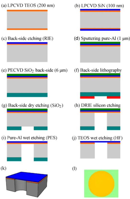
Membranes were fabricated following the steps shown in Figure1(a)-1(j). As substrate we em-ployed a double-side-polished Si wafer with a thickness of 500 µm and a RMS surface roughness lower than 1 nm. Prior fabrication the wafers were cleaned by immersing them in 99% HNO3and
in 65% HNO3at 110◦C. A 200-nm-thick SiO2layer was then deposited by LPCVD using
tetraethy-lorthosilicate (TEOS) as precursor [step(a)]. The LPCVD TEOS has a low compressive stress and works as etching stop layer during the DRIE etch. The fabrication followed with the LPCVD depo-sition of a 100-nm-thick SiNx layer [step (b)]. The depodepo-sition recipe was optimized for a residual tensile stress of about 1 GPa,18measured by wafer curvature (TENCOR Flexus FLX-2908). After
the back-side etching [step (c)], a low-stress 1-µm-thick layer of pure Al was sputtered on the front side [step (d)]. This layer served to protect the SiNxduring the DRIE etch. A 6-µm-thick oxide layer
was deposited on the backside by means of plasma enhanced chemical vapor deposition (PECVD) [step (e)]. Circular (square) holes with a diameter (side) up to 1.5 mm were patterned into this layer [step (f-g)]. The Si was then locally removed [step(h)] by means of DRIE (two pulse BOSCH process in Omega i2L Rapier). The etching rates were about 1.38 µm/cycle for Si and 5 nm/cycle for the PECVD oxide. Finally, the SiNxmembrane was released by first stripping the Al layer [step(i)] using
a PES solution and then by etching the TEOS oxide [step (j)] by means of an HF-based solution. We point out that metal and oxide layers are only protective and do not concur in determining the shape. The etching of the silicon frame, that defines the membrane’s shape, is fully realized by DRIE.
We focus the analysis of the mechanical resonance frequencies on the circular membranes, due to their original shape with respect to the more common square membranes. The theoretical resonance frequencies in a circular membrane are given by the expression fmn= f0αmnwhere αmnis the n-th
root of the Bessel polynomial of order m, and f0=2π1
T
ρ1R (T is the stress, ρ the density, R the
radius of the membrane). The modal shapes of the first 0n and 1n modes are shown in Figure2. We have measured the modal frequencies from a thermal spectrum acquired using a Michel-son interferometer (Fig.3), with the sample kept in a vacuum chamber. In Fig.4(a)we show the experimental resonance frequencies divided by the respective αmn, for the first m= 0 and m = 1
order modes. We expect a constant value, equal to f0. It appears that the lower modes slightly (but
systematically) deviate from the predicted behavior, with a maximum spread of just 4%, probably due to boundary effects, likely influenced by the clamping. We can extrapolate an asymptotic exper-imental value of f0≃ 114 kHz, to be compared with f0= 118.6 kHz that is calculated using the
nominal parameters R= 0.75 mm, T = 1 GPa and ρ = 3200 kg/m3. The agreement is very good.
We also remark that measurements taken at different times (entailing few degrees variations of the room temperature) yield fluctuations of the experimental f0by 2 − 3%.
An interesting property of the circular membrane is that the effective modal mass depends on the modal index, as opposed to the square membranes. Namely, the effective mass of the 0n modes for a centered, δ–like readout is M0n= M(J1(α0n))2, where M is the physical mass of the
FIG. 1. (a)-(j) Fabrication steps. (k) Section view of the finished device. (l) Optical microscope image of a circular membrane of diameter 1.5 mm.
0.043). The mass is lower at higher index because the modal displacement is more concentrated in the center, while it remains homogeneous for a square membrane. For comparison, in the case of a square membrane the effective mass of the odd modes is M/4. A reduced effective mass, increasing the susceptibility, is a useful property in opto-mechanics experiments. In the realistic case of a
065004-4 Serra et al. AIP Advances 6, 065004 (2016)
FIG. 2. Modal shape of the first 0n and 1n modes of a circular membrane. The color scale, from light gray to red, is proportional to the absolute displacement from the equilibrium position.
centered, Gaussian readout with 1/e2width w, the effective mass becomes:
M0n = M*. , J1(α0n) 4 w2 J0(α0nr/R) exp ( −2r2 w2 ) rdr + / -2 . (1)
In Fig.4(b)we report the experimental values of M0nfor the first modes, derived from the areas A0n
of the thermal peaks in the displacement spectrum using A0n= M kBTK
0n(2π f0n)2 (kB is the Boltzmann constant and TK the temperature). They are compared with the theoretical values calculated for a
realistic w = 0.15 mm (showing a good agreement) and with a pointlike readout.
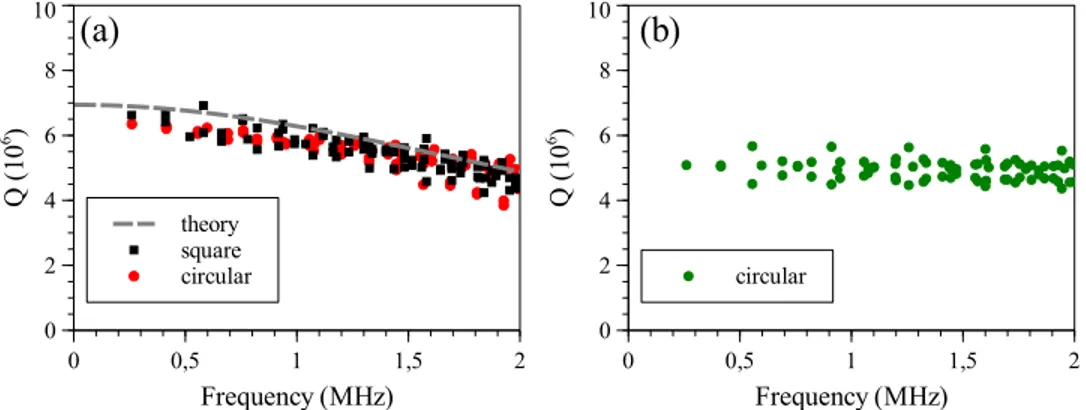
We have verified by Finite Element (FE) analysis that the expected quality factor is similar to that of a square membrane with the same modal frequency of the first mode. In fact, for each mode, a FE routine can evaluate the energy stored in different parts of the systems and can estimate the overall quality factor from the loss angle assigned to each part.19To validate our procedure we have
verified (Figure5(a)) that the quality factors of the modes of the square membrane evaluated by FE are in good agreement with the values expected from the theory. For a square membrane of side 1.52 mm, thickness 100 nm and internal stress 1 GPa, the quality factor envelope can been evaluated as:20
Qsquare≃
1.1 × 10⁷
1+ 1.35 × 10⁻¹³f2 (2)
where f is the frequency of the modes and the intrinsic loss has been set as 1/Q= 2 × 10⁻³, the
room temperature value.10The case of a circular membrane is then solved with the same FE routine,
obtaining quite similar values (Fig.5(a)). Note that the loss (1/Q) grows with the frequency because higher order modes have an increasing number of nodal lines.
The simulation can take into account also the loss from the substrate supporting the membrane, that has not been obtained in closed form yet. In fact the borders of the membrane bends during the oscillation and the first layer of the substrate is subjected to a mechanical strain. This contribution is
FIG. 3. Typical noise power spectral density (PSD) of the interferometer output; the modal frequencies can be clearly seen above background noise.
FIG. 4. (a) Resonance frequencies of the first 0n (open circles) and 1n (stars) modes af a R= 0.75 mm circular membrane, divided by the respective αm n. (b) Experimental effective mass M0nof the first modes (crosses), theoretical values calculated for a centered Gaussian readout with width w= 0.15 mm (closed circles) and for a pointlike readout (triangles).
negligible when the SiNxlayer is directly grown on silicon, but it may become relevant in our case,
as the membrane is grown over a SiO2layer. At room temperature the loss angle of SiO2is as low
as 1/Q= 5 × 10⁻⁵and we have not found an additional contribution.21At liquid helium temperature
the expected loss22for SiN
x reduces to 1/Q= 2 × 10⁻⁵, while for SiO2it grows to 1/Q= 7 × 10⁻⁴.
In this case the substrate becomes the main source of loss and limits the maximum quality factor to 5 × 10⁶, as shown in Figure5(b). We note here that the loss is set by the contribution of the border
and the frequency dependence can no longer be seen in the simulation data. We point out that these results are necessarily approximate, as the intrinsic loss angle value can be strongly dependent on the deposition procedure or on the thickness of the adhesion layer.22
The mechanical quality factor Q of the modes of different membranes has been measured both at room and at cryogenic temperatures, by driving the different resonances with a piezoelectric glued on the sample mount, and observing the ring-down with a Michelson interferometer. At room temperature, the Q values are very scattered, ranging from few thousands up to 2 × 10⁵. This feature is very common in SiNxmembranes, and is due to the coupling with the frame and, through it, with
the sample holder. At cryogenic temperatures, the values of Q are still scattered, but globally higher. With a 1.5 mm diameter membrane on a 5 mm side, square frame clamped between two copper plates, we could measure a maximum Q of 0.65 × 10⁶, at 8 K. With a 1 mm side, square membrane
close to the edge of a 5 × 20 mm2frame, glued on the opposite edge to a copper block, we could
measure Q values up to 1.3 × 10⁶ at 13 K. As we aim to develop a general-purpose device, with
FIG. 5. Finite Elements estimate of quality factor of tensioned membranes. (a) Room temperature simulations for a square membrane (squares) with side 1.52 mm and for our circular membrane (closed circles). The dashed line is the theoretical prediction Eq. (2) for the square membrane. (b) Low temperature simulation for the circular membrane. Here the quality factor is limited by the SiO2adhesion layer.
065004-6 Serra et al. AIP Advances 6, 065004 (2016) features independent from the details of the experimental apparatus, we did not optimize the efforts to improve the best measured quality factor by trying different mounting systems. We also note that, even if the meaningful clamping losses do not permit a better assessment, the FEM calculations indicate that the loss from the SiO2adhesion layer limits the expected Q for membranes of our size
to about 5 × 10⁶(Figure5(b)). In this context, we estimate that a Q higher than 106it is enough to
motivate the future development of on-chip isolation system for these membranes.
We characterized the optical properties of a circular membrane of nominal radius R= 0.6 mm, with thickness Ld= 97.27 ± 0.01 nm and index of refraction at λ = 1064 nm nR= 2.0210 ± 0.0005,
measured during production [step (b)] by variable angle spectroscopic ellipsometry (VASE). These values have been confirmed by polarization-resolved transmission measurements again at λ = 1064 nm, performed on the final, diced samples. These latter measurements provide an intensity reflectivity at normal incidence |rd|2= 0.355 ± 0.002, perfectly consistent with the expression for
the amplitude reflection and transmission coefficients of a dielectric membrane of thickness Ldand
refractive index n,
rd= (n 2− 1
) sin β
2in cos β+ (n2+ 1) sin β, (3)
td=
2n
2in cos β+ (n2+ 1) sin β, (4)
where β= nkLd= 2πnLd/λ. When n = nR is real there is no optical absorption, but in general
n= nR+ inI, with the small but nonzero imaginary part nI providing a measure of optical
absorp-tion. In order to accurately evaluate it, we have placed the membrane between two Al cylinders, and we have inserted it in a L= 9.03 cm long cavity at room temperature formed by two spherical mirrors of radius of curvature 7.5 cm. The high-frequency component of the Pound-Drever-Hall (PDH) signal used to lock the cavity was acquired for the preliminary analysis of the mechanical modes at a vacuum chamber pressure of 1.7 × 10⁻²mbar. The fundamental eigenfrequency is found
to be f01∼ 348.5 kHz, consistent with the theoretical expectation if we assume R= 0.615 mm.
The detected optical cavity modes as a function of the membrane position are also consistent with the theoretical model obtained with the cavity and membrane parameters.23,24 Finally the cavity
finesse, FT, as a function of the membrane position has been measured (see Fig.6) by the ringdown
technique. The laser beam, deflected by an acousto-optic-modulator (AOM) and sent into the cav-ity, is switched off in 50 ns after the transmitted light has reached a threshold level. The leakage of transmitted light is monitored to estimate the cavity decay-time, which is fitted with a single exponential form whose time constant, τ, is related to FT via FT = πcτ/L. Repeating the finesse
measurement for different positions of the membrane as reported in Fig.6, allows to estimate nI
and the roughness of the membrane. For fitting the finesse data we consider the transfer function of a cavity with a membrane in the middle. The cavity consists of two semi-cavities; denoting with z the position of the membrane with respect to the cavity center, and assuming for the reflection and transmission coefficients of the mirrors r1= r2=
√
R and t1= t2=
√
T , we derive the following expression for the intensity transmission:
Tc = |T td| 2 1+ 2rd √ R cos(2k z)eik L+ R(t2 d+ r 2 d)e2ik L 2. (5)
In the ideal case R= 1 and n is real, so that t2 d+ r
2
d= exp {2i arg(rd)} = exp {2iφr}, the
eigenfre-quencies of the cavity modes are given by the zeros of the denominator of the cavity transmission [cos(k L + φr) + |rd| cos(2k z)]2= 0, which gives the results in Ref.24
2k L= ν 2π
∆νF S R = −2φ
r+ 2cos−1[−|rd| cos(2k z)] . (6)
When R < 1 and in the presence of absorption the resonance frequencies of the cavity modes are determined by the maxima of the transmission Tc given by Eq. (5), and the finesse can be obtained
from the width of the transmission peaks. Roughness can be introduced following Refs.25–27, ac-cording to which any optical element with a given roughness is responsible for a modification of the
FIG. 6. Plot of the cavity finesse, FT versus membrane position along the cavity axis. Red-symbols represent data for a circular-membrane, 1.2 mm diameter, and 97 nm thickness. Red-line represents the best fit with fitting parameters ¯nI = (1.97±0.08)×10−6and ¯σ
opt= (287±4) pm, and with the following fixed parameters: the membrane thickness Ld= 97 nm, the real part of the refractive index nR= 2.021, the cavity length L = 9.03 cm, the wavelength λ = 1064 nm, and the empty-cavity finesse Fv= 53500±100, which is evaluated as mean value of the data shown as blue-symbols. Green-symbols represent data for a square-membrane, 1 mm side, 50 nm thickness by Norcada, The green-line is the fitting with parameters nI= (1.0±0.01)×10−5and σopt= (280±10) pm. Dashed-gray (dotted-gray) curves represent theoretical expectation for the circular membrane with parameters fixed as σopt= 0 (nI= 0) and nI/ ¯nI= .5, 1, 2 (σopt/ ¯σopt= .5, 1, 2), from upper to lower curve. They demonstrate the different contribution of absorption and roughness to the finesse behaviour upon membrane position.
wavefront and therefore leads to a scattering loss from the incident optical mode into all the other cavity modes. This scattering into other modes induced by an effective optical roughness σoptcan be
modeled by including a factor
exp[−(2kσopt)2] multiplying rdin eq. (3). Fig.6shows the best fits
for the set of data (red symbols) taken for the 1.2 mm–diameter circular membranes. We have taken nI and σoptas fitting parameters, while we have kept fixed all the other parameters (Ld= 97 nm,
nR= 2.021, L = 9.03 cm, λ = 1064 nm, and Fv= 53500 ± 100 corresponding to R = 0.9999413).
While the λ/2 periodicity is caused by the absorption which is maximum at the antinodes and minimum at the nodes of the cavity field, the membrane roughness causes scattering which instead does not significantly depend upon the membrane axial position (as shown in Fig.6). The fit gives an imaginary part of the refractive index ¯nI = (1.97 ± 0.08) × 10−6and ¯σopt= (287 ± 4) pm. As a
comparison, the results for a 1 mm side, 50 nm thickness membrane by Norcada28are reported with fitting parameters nI= (1.00 ± 0.01) × 10−5and σopt= (280 ± 10) pm. The circular membranes we
fabricated present a similar effective optical roughness with respect to a commercial square one but a lower absorption. As regards standard AFM measurement of roughness, we measured for our membranes σrms= 0.7 ± 0.1 nm over scan areas of 1µm × 1µm.
In conclusion, we developed and validated a general fabrication procedure for free-standing large area high-stress SiNx membranes of any shape with a good dimensional precision by using
DRIE etching. Possible improvements of the process could be obtained by the use of silicon sub-strates with a lower initial roughness. This work is a crucial step toward the integration of SiNx
membranes in hybrid systems and on-chip mechanical isolation.
We mention that some interesting development have been recently reported,29,30published
af-ter the submission of this work. Here small membranes (about 100 × 100 µm2) are supported by
trampolines that act as flexure elements, and demonstrate the effectiveness of a careful engineer-ing in obtainengineer-ing high quality factors. These resonators also have a very small mass, obtained at the expense of a reduced heat management capability, and therefore target different experimental regimes compared to large membranes.
This work has been supported by MIUR (PRIN 2010-2011) and by INFN (HUMOR project). A.B. acknowledges support from the MIUR under the “FIRB-Futuro in ricerca 2013” funding program, project code RBFR13QUVI.
065004-8 Serra et al. AIP Advances 6, 065004 (2016) 1M. Aspelmeyer, T.J. Kippenberg, and F. Marquardt,Rev. Mod. Phys.86, 1391 (2014).
2T.P. Purdy, R.W. Peterson, and C.A. Regal,Science339, 801 (2013).
3M. Bawaj, C. Biancofiore, M. Bonaldi, F. Bonfigli, A. Borrielli, G. Di Giuseppe, L. Marconi, F. Marino, R. Natali, A. Pontin, G.A. Prodi, E. Serra, D. Vitali, and F. Marin,Nat. Commun.6, 7503 (2015).
4A.H. Safavi-Naeini, S. Groblacher, J.T. Hill, J. Chan, M. Aspelmeyer, and O. Painter,Nature500, 185 (2013). 5T.P. Purdy, P.-L. Yu, R.W. Peterson, N.S. Kampel, and C.A. Regal, Phys. Rev. X 3, 031012 (2013).
6D.J. Wilson, C.A. Regal, S.B. Papp, and H.J. Kimble,Phys. Rev. Lett.103, 207204 (2009).
7J.D. Thompson, B.M. Zwickl, A.M. Jayich, Florian Marquardt, S.M. Girvin, and J.G.E. Harris,Nature452, 72-75 (2008). 8R.W. Andrews, R.W. Peterson, T.P. Purdy, K. Cicak, R.W. Simmonds, C.A. Regal, and K.W. Lehnert,Nat. Phys.10, 321326
(2014).
9Catvu H. Bui, Jiangjun Zheng, S. W. Hoch, Lennon Y. T. Lee, J. G. E. Harris, and Chee Wei Wong,Appl. Phys. Lett.100, 021110 (2012).
10L.G. Villanueva and S. Schmid,Phys. Rev. Lett.113, 227201 (2014). 11C.T. Leondes, Mems/Nems Handbook (Springer, 2006).
12D. R. Southworth, R. A. Barton, S. S. Verbridge, B. Ilic, A. D. Fefferman, H. G. Craighead, and J. M. Parpia,Phys. Rev. Lett.102, 225503 (2009).
13P. Galambos, K. Zavadil, R.J. Shul, C. Lober Willison, and S.L. Miller, Proc. SPIE 3877, Microfluidic Devices and Systems II, 273 (1999).
14E. Serra, A. Borrielli, F. S. Cataliotti, F. Marin, F. Marino, A. Pontin, G. A. Prodi, and M. Bonaldi,Appl. Phys. Lett.101, 071101 (2012).
15A. Borrielli, A. Pontin, F. S. Cataliotti, L. Marconi, F. Marin, F. Marino, G. Pandraud, G. A. Prodi, E. Serra, and M. Bonaldi, Phys. Rev. Applied3, 054009 (2015).
16P.-L. Yu, K. Cicak, N.S. Kampel, Y. Tsaturyan, T.P. Purdy, R.W. Simmonds, and C.A. Regal,Appl. Phys. Lett.104, 023510 (2014).
17Y. Tsaturyan, A. Barg, A. Simonsen, L.G. Villanueva, S. Schmid, A. Schliesser, and E.S. Polzik,Opt. Express22, 6810 (2014).
18P.J. French, P.M. Sarro, R. Mallée, E.J.M. Fakkeldij, and R.F. Wolffenbuttel,Sens. Actuators A58, 149 (1997).
19E. Serra, M. Bonaldi, A. Borrielli, L. Conti, G. Pandraud, and P.M. Sarro,Sensors and Actuators A: Physical227, 48 (2015). 20P.-L. Yu, T. P. Purdy, and C. A. Regal,Phys. Rev. Lett.108, 083603 (2012).
21M. Principe, I.M. Pinto, V. Pierro, R. DeSalvo, I. Taurasi, A.E. Villar, E.D. Black, K.G. Libbrecht, C. Michel, N. Morgado, and L. Pinard,Phys. Rev. D91, 022005 (2015).
22X. Liu, T.H. Metcalf, Q. Wang, and D.M. Photiadis,Mater. Res. Soc. Symp. Proc.989, A22-01 (2007).
23C. Biancofiore, M. Karuza, M. Galassi, R. Natali, P. Tombesi, G. Di Giuseppe, and D. Vitali,Phys. Rev. A84, 033814 (2011).
24A.M. Jayich, J.C. Sankey, B.M. Zwickl, C. Yang, J.D. Thompson, S.M. Girvin, A.A. Clerk, F. Marquardt, and J.G.E. Harris, New J. Phys.9, 095008 (2008).
25D. Kleckner, W.T.M. Irvine, S.S.R. Oemrawsingh, and D. Bouwmeester,Phys. Rev. A81, 043814 (2010). 26W. Winkler, R. Schilling, K. Danzmann, J. Mizuno, A. Rüdiger, and K.A. Strain,Appl. Opt.33, 7547 (1994). 27The Virgo collaboration, The VIRGO physics book, Vol. II, available online athttp://www.virgo-gw.eu/vpb/. 28Norcada Inc.,http://www.norcada.com.
29C. Reinhardt, T. Müller, A. Bourassa, and J.C. Sankey, Phys. Rev. X 6, 021001 (2016). 30R.A. Norte, J.P. Moura, and S. Gröblacher,Phys. Rev. Lett.116, 147202 (2016).