School of Advanced Studies
Dottorato di Ricerca in Scienze e Tecnologie
Computer Science - XXXI Ciclo
Formalisation of BPMN Models:
a Focus on Correctness Properties
Relatore Dottorando
Prof. Flavio Corradini Chiara Muzi
Co-Relatore
Prof. Francesco Tiezzi
Commissione Esaminatrice Prof. Thomas T. Hildebrandt Prof. Alberto Lluch Lafuente
School of Advanced Studies
Doctor of Philosophy in Sciences and Technology
Computer Science - XXXI Cycle
Formalisation of BPMN Models:
a Focus on Correctness Properties
Supervisor PhD Candidate
Prof. Flavio Corradini Chiara Muzi
Co-Supervisor Prof. Francesco Tiezzi
Doctoral Examination Committee Prof. Thomas T. Hildebrandt
Prof. Alberto Lluch Lafuente
The BPMN standard has a huge uptake in modelling business processes within the same organisation or involving multiple ones. Its primary goal is to create a standardised bridge for the gap between process design and process implementation in order to entirely automate the business process management lifecycle. In this context, the BPMN lack of a precise seman-tics represents a big issue, since it can lead to different interpretations, and hence implementations, of its features. Thus, providing a formal semantics of the BPMN notation is crucial for shaping IT systems and guaranteeing that these systems behave as they are supposed to do. On the one hand a formal semantics allows to overcome misunderstandings due to the use of natural language in the standard; on the other hand it enables the study of model properties, paving the way for correctness verification. This is in-deed a clearly perceived need, as business process models, while primarily intended for process documentation and communication, are nowadays of-ten also used as input for developing process-aware information systems and service-oriented applications. High quality of business process models is im-portant for all these goals and correctness is an imim-portant indicator of it. Its relevance is also highlighted by the observation that incorrect models can lead to wrong decisions regarding a process and to unsatisfactory implemen-tations of information systems.
Tackling the above issues, this thesis contributes to the definition of a direct BPMN operational semantics, providing a uniform formal framework to study BPMN models and their main correctness properties. The formal-isation allows to formally characterise important properties in the business process modelling domain, namely well-structuredness, safeness and sound-ness, thus classifying BPMN models according to the properties they satisfy. This leads to achieve advances in classifying BPMN models, by directly ad-dressing BPMN models and their specificities. Concerning the formalisation, first a formal semantics for a core subset of BPMN elements is provided and then it is extended, by including other elements and business perspectives.
Specifically, are considered features widely recognised as tricky and challeng-ing to be formalised such as the OR-Join gateway, the sub-process element and multiple interacting participants, who exchange messages and data, in order to check if the obtained results are still valid in an extended framework.
Pursuing a PhD project is both a difficult and enjoyable experience. It’s just like playing a tennis match, game after game, accompanied with bitterness, hardships, frustration, encouragement and trust and with so many people’s kind help. When I reached this beautiful win, I realised that it was, in fact, teamwork that got me there. Though it will not be enough to express my gratitude in words to all those people who helped me, I would still like to give my many, many thanks to all these people.
The PhD process successfully ends with the thesis defence, that could be not possible with the feedback provided by the committee members, professor Thomas T. Hildebrandt and professor Alberto Lluch Lafuente; thank you for your brilliant comments and suggestions.
Before coming to an end a process has to start; this was possible thanks to the PhD admissions committee, in particular to professor Emanuela Merelli, coordinator of the PhD program, and professor Andrea Polini.
The PhD process continued thanks to the whole PROS Lab group that welcomed me and contributed immensely to my personal and professional time at Unicam. The group has been a source of friendships as well as good advice and collaboration.
In parallel, I would like to thank my supervisor professor Flavio Corradini for having the opportunity to learn from his research expertise and for the excellent example he has provided as a successful professor and rector of my university. Many thanks to my co-supervisor professor Francesco Tiezzi for his valuable guidance, inputs and support I received throughout the research work. He offered me so much advice, supervising me and always guiding me in the right “formal” direction. Many many thanks to professor Barbara Re, who encouraged me in undertaking this PhD programme. She was the first person who believed I could make the big jump from Mathematics to Computer Science. This was possible also because of her unconditional support with an amicable and positive disposition. She has always made herself available to clarify my doubts despite her busy schedules and she has always been present
with moral and material support, advice and encouragement, contributing in avoiding an abnormally termination of the PhD process!!! I am also deeply thankful to the activity performed by my colleagues of adventures, Fabrizio, Andrea and Lorenzo. They offered me constant support and cooperation and, most of all, they had considered me as the most beautiful woman of the office!!!!
A real process involves many other external participants, who can pro-vided support by sharing experiences, messages, and love. Among these I have to thank my family, that always believed in me and was there for prac-tical and moral support in all those things of life beyond doing a PhD.
Last but not least, I thank a very special person, my boyfriend, David for his continued and unfailing support and understanding, that contributed in making the thesis completion possible. I know you are the person who expresses feelings with actions rather than words: you were always around at times I thought that it is impossible to continue, you pushed and motivated me and most of all you have always made me happy!
• Corradini, F., Fornari, F., Muzi, C., Polini, A., Re, B., and Tiezzi, F. On Avoiding Erroneous Synchronization in BPMN Processes. 20th International Conference on Business Information Systems, BIS 2017, Poznan, Poland, Volume 288 of LNBIP Springer, pp. 106-119, 28-30 June 2017.
• Corradini, F., Muzi, C., Re, B., Rossi, L. and Tiezzi, F. Global vs. Lo-cal Semantics of BPMN 2.0 OR-Join. 44th International Conference on Current Trends in Theory and Practice of Computer Science, SOFSEM 2018, Krems an der Donau, Austria, Volume 10706 of LNCS Springer, pp. 321-336, 29 January - 2 February 2018.
• Corradini, F., Muzi, C., Re, B., and Tiezzi, F. A Classification of BPMN Collaborations based on Safeness and Soundness Notions. Com-bined 25th International Workshop on Expressiveness in Concurrency and 15th Workshop on Structural Operational Semantics, EXPRESS/-SOS 2018, Beijing, China, Volume 276 of Electronic Proceedings in Theoretical Computer Science, pp. 37-52, 3 September 2018.
• Corradini, F., Muzi, C., Re, B., Rossi, L. and Tiezzi, F. Animating Multiple Instances in BPMN Collaborations: from Formal Semantics to Tool Support. 16th International Conference on Business Process Management, BPM 2018, Sydney, Australia, Volume 11080 of LNCS Springer, pp. 83-101, 9-14 September 2018.
• Corradini, F., Muzi, C., Re, B., Rossi, L. and Tiezzi, F. MIDA: Mul-tiple Instances and Data Animator. 16th International Conference on Business Process Management, BPM 2018 (Demo), Sydney, Australia, Volume 2196 of CEUR Springer, pp. 86-90, 9-14 September 2018. • Muzi, C., Pufhal, L., Rossi, L., Weske, M., and Tiezzi, F. Formalising
con-ference on the Practice of Enterprise Modelling Vienna, Volume 335 of LNBIP Springer, pp. 3-20, 31 October - 2 November, 2018.
Abstract of the Dissertation v
Acknowledgements vii
List of Publications ix
List of Figures xv
List of Tables xix
I
Introduction & Background
1
1 Introduction 3
1.1 Motivations . . . 3
1.2 Research Objectives . . . 4
1.3 Thesis Structure . . . 5
2 Background 7 2.1 Business Process Management . . . 7
2.2 Business Process Model and Notation 2.0 . . . 9
2.2.1 BPMN Notation . . . 10
2.2.2 Running Example . . . 15
2.3 Relevant Business Process Properties . . . 16
2.4 Operational Semantics . . . 18
II
BPMN Formalisation and Correctness Properties 21
3 Core BPMN Operational Semantics 23 3.1 Running Example . . . 243.2 Formal Framework . . . 25
3.2.1 Syntax . . . 25
3.2.2 Semantics . . . 29
3.3 Comparison with other Approaches . . . 34
3.3.1 BPMN Direct Formalisations . . . 34
3.3.2 BPMN Formalisations via Mapping . . . 35
4 BPMN Correctness Properties 37 4.1 Properties of BPMN Collaborations . . . 38
4.1.1 Well-Structured BPMN Collaborations . . . 38
4.1.2 Safe BPMN Collaborations . . . 40
4.1.3 Sound BPMN Collaborations . . . 41
4.2 Relevance into Practice . . . 42
4.3 Classification Results . . . 44
4.3.1 Advances with respect to already available classifications 44 4.3.2 Advance in Classifying BPMN Models . . . 46
4.4 Relationships among Properties . . . 47
4.4.1 Well-structuredness vs. Safeness in BPMN . . . 48
4.4.2 Well-structuredness vs. Soundness in BPMN . . . 49
4.4.3 Safeness vs. Soundness in BPMN . . . 50
4.5 Class of (Sound) Unsafe Models . . . 51
4.5.1 Motivating Scenario . . . 51
4.5.2 Methodology . . . 53
4.5.3 Approach at Work . . . 56
4.6 Compositionality of Safeness and Soundness . . . 57
4.6.1 On Compositionality of Safeness . . . 57
4.6.2 On Compositionality of Soundness . . . 59
4.7 Comparison with other Approaches . . . 60
III
Extended Framework
63
5 OR-Join Gateway 65 5.1 Running Example . . . 665.2 Towards the OR-Join Formal Definition . . . 67
5.2.1 From BPMN 2.0 Specification to Process Execution . . 67
5.2.2 Preliminaries . . . 69
5.3 Formal Framework . . . 70
5.3.1 Syntax . . . 70
5.3.2 Semantics . . . 71
5.4 Local Semantics of BPMN OR-Join . . . 74
5.4.1 Syntax . . . 74
5.5 Global vs. Local Semantics . . . 85 5.6 Properties of BPMN Processes . . . 87 5.6.1 Well-Structured BPMN Processes . . . 87 5.6.2 Safe BPMN Processes . . . 88 5.6.3 Sound BPMN Processes . . . 89 5.7 Classification Results . . . 89
5.8 Comparison with other Approaches . . . 90
5.8.1 OR-Join Formalisations . . . 90
5.8.2 Reasoning on Correctness Properties . . . 94
6 Sub-Processes 95 6.1 Running Example . . . 96 6.2 Formal Framework . . . 97 6.2.1 Syntax . . . 97 6.2.2 Semantics . . . 99 6.3 Properties of BPMN Collaborations . . . 100 6.3.1 Well-Structured BPMN Collaborations . . . 100 6.3.2 Safe BPMN Collaborations . . . 101 6.3.3 Sound BPMN Collaborations . . . 102 6.4 Classification Results . . . 102
6.5 Relationships among Properties . . . 103
6.5.1 Well-structuredness vs. Safeness in BPMN . . . 104
6.5.2 Well-structuredness vs. Soundness in BPMN . . . 105
6.5.3 Safeness vs. Soundness in BPMN . . . 105
6.6 Compositionality of Safeness and Soundness . . . 106
6.6.1 On Compositionality of Safeness . . . 106
6.6.2 On Compositionality of Soundness . . . 106
6.7 Comparison with other Approaches . . . 106
6.7.1 Sub-Processes Formalisations . . . 107
6.7.2 Reasoning on Correctness Properties . . . 107
7 Multiple Instances and Data 109 7.1 Running Example . . . 110 7.2 Formal Framework . . . 112 7.2.1 Syntax . . . 112 7.2.2 Semantics . . . 116 7.3 Properties of BPMN Collaborations . . . 124 7.3.1 Well-Structured BPMN Collaborations . . . 124 7.3.2 Safe BPMN Collaborations . . . 125 7.3.3 Sound BPMN Collaborations . . . 126 7.4 Classification Results . . . 127 7.4.1 Well-structuredness vs. Safeness in BPMN . . . 128 7.4.2 Well-structuredness vs. Soundness in BPMN . . . 129
7.4.3 Safeness vs. Soundness in BPMN . . . 130
7.5 Compositionality of Safeness and Soundness . . . 130
7.5.1 On Compositionality of Safeness . . . 130
7.5.2 On Compositionality of Soundness . . . 131
7.6 MIDA Animator . . . 131
7.7 Comparison with other Approaches . . . 135
7.7.1 Multiple Instances and Data Formalisations . . . 135
7.7.2 Reasoning on Correctness Properties . . . 136
8 Formalising BPMN Patterns 139 8.1 Core BPMN Patterns . . . 140
8.2 BPMN Patterns with OR Gateways . . . 153
8.3 BPMN Patterns with Sub-Processes . . . 154
8.4 BPMN Patterns with Multiple Instances . . . 155
8.5 Semantics Validation . . . 160
IV
Conclusions & Future Work
163
9 Conclusions and Future Work 165 Bibliography 171 A Appendix: Notation Correspondence 183 A.1 Core BPMN . . . 183A.2 OR-Join . . . 185
A.3 Sub-Processes . . . 186
A.4 Multiple Instances and Data . . . 186
B Appendix: Definitions 189 C Appendix: Proofs 195 C.1 Core BPMN . . . 195
C.2 OR-Join . . . 208
C.3 Sub-Processes . . . 217
2.1 Business Process Perspectives [85, Sec. 2.4]. . . 8 2.2 BPMN Pools. . . 10 2.3 Considered BPMN Activities. . . 10 2.4 BPMN Connecting Edges. . . 11 2.5 Considered BPMN Events. . . 12 2.6 Considered BPMN Gateways. . . 12 2.7 Considered BPMN Artefacts. . . 13
2.8 BPMN Types of Data Objects. . . 14
2.9 Paper Reviewing Collaboration Model. . . 15
3.1 Paper Reviewing Collaboration Model. . . 24
3.2 Syntax of BPMN Collaboration Structures. . . 25
3.3 BPMN Semantics - Process Level. . . 32
3.4 BPMN Semantics - Collaboration Level. . . 34
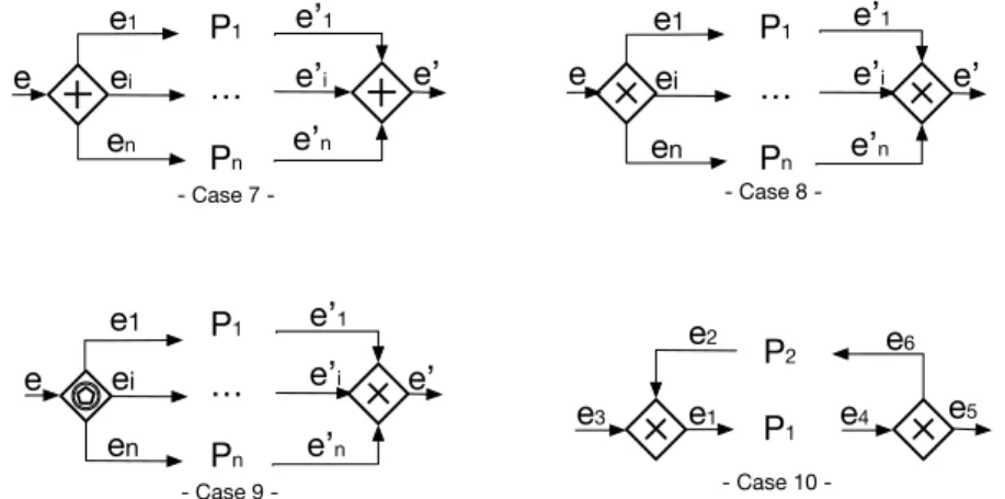
4.1 Well-structured Core Elements (cases 7-10). . . 40
4.2 Classification of BPMN Collaborations. . . 45
4.3 Impact of the Terminate Event on the Classification. . . 47
4.4 Unsound Process. . . 47
4.5 Sound Process. . . 47
4.6 Safe BPMN Collaboration not Well-structured . . . 49
4.7 Example of Sound Process not Well-Structured. . . 50
4.8 Paper Reviewing Collaboration Model (revisited). . . 52
4.9 Graphical notation of check-in and check-out annotations. . . 55
4.10 Paper Reviewing Collaboration Execution with Tokens id. . . 56
4.11 Safe Collaboration with Safe and Unsafe Processes. . . 58
4.12 Safe Collaboration with Unsafe Processes. . . 58
4.13 Unsafe Collaboration with Unsafe Processes. . . 58
4.14 Example of Unsound Collaboration with Sound Processes. . . 60
5.1 Paper Submission Process. . . 66
5.2 Paper Submission Process Structure. . . 67
5.3 OR-Join Semantics According to the OMG Standard BPMN 2.0 (p. 436). . . 68
5.4 OR-Join Activation. . . 68
5.5 Syntax of BPMN Process Structures. . . 71
5.6 BPMN Global Semantics. . . 71
5.7 Running Example. . . 73
5.8 BPMN Syntax of Marked Processes. . . 75
5.9 BPMN Local Semantics - Evolution of Live Tokens. . . 77
5.10 BPMN Local Semantics - Dead Status Propagation. . . 80
5.11 Running Example. . . 81
5.12 Example of Vicious Circle. . . 82
5.13 OR-Join Model Fragment. . . 85
5.14 Experiment Trend. . . 86
5.15 OR-Join with Deadlock Upstream. . . 93
5.16 Signavio Simulation Error. . . 93
6.1 Paper Reviewing Collaboration Model . . . 97
6.2 BPMN Sub-Process Semantics. . . 100
6.3 Reasoning at Process (a) and Collaboration (b) Level. . . 102
6.4 Unsound Process. . . 103
6.5 Sound Process with an Unsound Sub-Process. . . 103
6.6 Example of Unsound and Message-Relaxed Unsound. . . 104
6.7 Example of Message-Relaxed Sound and Unsound Collabora-tion. . . 104
6.8 Example of Message-Relaxed Sound and Sound Collaboration. 104 7.1 Paper Reviewing Collaboration Model. . . 110
7.2 Structures of Data Objects (a) and Messages (b) of the Paper Reviewing Example. . . 112
7.3 BNF Syntax of BPMN Collaboration Structures. . . 112
7.4 Textual Representation of the Running Example (Part I). . . 115
7.5 Textual Representation of the Running Example (Part II). . . 116
7.6 BPMN Process Semantics (Part I). . . 119
7.7 BPMN Process Semantics (Part II). . . 120
7.8 BPMN Collaboration Semantics. . . 123
7.9 MIDA Web Interface. . . 132
7.10 MIDA Animation. . . 133
7.11 Guard Violation. . . 134
8.1 Sequence. . . 141
8.3 Synchronisation. . . 142 8.4 Exclusive Choice. . . 142 8.5 Simple Merge. . . 143 8.6 Deferred Choice. . . 143 8.7 Cancel Case. . . 144 8.8 Direct Allocation. . . 144 8.9 Commencement on Creation. . . 145 8.10 Send. . . 146 8.11 Receive. . . 147 8.12 Send/Receive. . . 148
8.13 Racing Incoming Messages (a). . . 149
8.14 Racing Incoming Messages (b). . . 149
8.15 Multi-responses. . . 150
8.16 Request with Referral. . . 152
8.17 Example of Relayed Request. . . 153
8.18 Multiple Choice. . . 153 8.19 Synchronising Merge. . . 154 8.20 Implicit Termination. . . 155 8.21 One-To-Many-Send. . . 156 8.22 One-From-Many-Receive. . . 157 8.23 One-To-Many Send/Receive. . . 158 8.24 Contingent Requests. . . 159
C.1 Example of Unsound Collaboration with Sound WS Processes. 206 C.2 Example of Unsafe but Sound Process. . . 207
C.3 Example of Unsafe but Sound Collaboration. . . 207
C.4 Example of Unsafe but Sound Process. . . 218
C.5 Example of Unsafe but Sound Collaboration. . . 219
C.6 Example of Unsound Process. . . 220
4.1 Classification of the Models in the BPM Academic Initiative
Repository. . . 43
5.1 Experiment Results. . . 86
5.2 Review on the OR-Join Semantics. . . 91
8.1 Semantics Validation Results. . . 161
Chapter
1
Introduction
Modelling activities is recognised as an important phase in the software life cycle. In particular, modelling business processes in complex organisations allows a better understanding on organisations work and, at the same time, it supports the development and the continuous improvement of related IT systems [69, 34]. A significant challenge is to provide a precise semantics of the used modelling languages to guarantee that the modelled behaviours do what they are supposed to do. This permits, not only to overcome misun-derstanding due to the use of natural language in the modelling languages specification, but also enables formal reasoning on model properties, so that diagnostic information can be reported on the diagram in a way that is under-standable by all process stakeholders. This is especially useful in the case of organisations involving different participants that need to properly interact. The main objective of this thesis is to provide a uniform formal frame-work to characterise business processes and their main correctness properties. This permits to classify models according to the properties they satisfy, thus providing systematic methodological advices for modelling business processes in a correct way. This chapter introduces the motivations and objectives that have driven this work and describes the thesis structure.
1.1
Motivations
The effective and efficient handling of business processes is a primary goal of organisations. Business Process Management (BPM) provides methods and techniques to support these endeavours [109]. Thereby, the main artefacts are business process models which help to document, analyse, improve, and automate organisation processes. For conducting a successful business, an organisation does not act alone, but it is usually involved in collaborations with other organisations. Therefore, it is interesting to consider collaborative
systems where participants can interact and share information and data. To ensure proper carrying out of such interactions, the participants should be provided with enough information about the messages they must or may send in a given context.
In this regard, Business Process Model and Notation (BPMN) [68] collab-oration diagrams result to be an effective way to represent how multiple par-ticipants cooperate to reach a shared goal. Even if widely accepted, BPMN has a major drawback related to the complexity of the semi-formal definition of its meta-model and the possible misunderstanding of its execution se-mantics defined by means of natural text description, sometimes containing misleading information [90]. These issues worsen when taking into account BPMN elements that have a particularly tricky behaviour and when consid-ering BPMN supporting tools, such as animators, simulators and enactment tools, whose implementations of the execution semantics may not be com-pliant with the standard and be different from each other, thus undermining models portability and tools effectiveness.
To overcome these issues, several formalisations have been proposed, usu-ally by means of mapping the BPMN notation to formal languages (e.g. Petri Nets [29], process calculi [113]). However, on the one hand models resulting from a mapping inherit constraints given by the target formal language and so far none of them considers specific and distinctive features of BPMN such as different abstraction levels (i.e., collaboration, process, and sub-process), the asynchronous communication model, and the notion of completion due to different types of end event (i.e., simple, message throwing, and terminate). On the other hand, less attention has been paid to provide a formal seman-tics capturing the interplay between control features, message exchanges, and data. This is a particularly important challenge in the BPM domain, as a precise semantics does not leave any room for ambiguity and is a prereq-uisite to ensure the appropriate carrying out, in practice, of processes and interactions among them. Moreover, a precise characterisation enables to formal reason on model properties at a level as close as possible to BPMN diagrams, so that the resulting findings are easily understandable by process stakeholders, and provide advices for modelling business process models in a correct way, avoiding errors in execution.
1.2
Research Objectives
The main objective of this thesis is to provide a formal characterisation of the BPMN semantics specifically given for collaboration models, with the aim of formally defining a classification of these models according to relevant properties of the business process domain. The intention is to introduce a unique formal framework to allow BPMN designers to achieve a better
understanding of their models, and relative properties. In order to deal with this objective, a set of sub-objectives has been established.
1. Provide a formal semantics for the core of BPMN elements by means of an Operational Semantics, specifically and directly given for BPMN, to enable the application of formal methods.
2. Consolidate the state of the art on business process correctness prop-erties through their formal definition in a uniform formal framework. 3. Achieve advances with respect to already available classifications of
BPMN models, by directly addressing BPMN collaboration models and their specificities.
4. Extend the formal framework by considering the OR-Join gateway, sub-processes, data objects and multiple interacting participants, who exchange messages and data, in order to show that the obtained results are still valid in an extended framework.
5. Validate the formal framework, both in terms of the considered BPMN elements and of the expected semantic behaviour.
1.3
Thesis Structure
The thesis is organized into four parts.
Part I - Introduction and Background is divided into two chapters. Chapter 1, Introduction, motivates the research work of this thesis, presenting its target objectives. Chapter 2, Background, provides back-ground materials for the understanding of the thesis with concepts from the Business Process Management area, with a focus on relevant prop-erties of the domain and some notions on formal methods techniques.
Part II - BPMN Formalisation and Correctness Properties is
di-vided into two chapters that exploit a formal characterisation of the collaborations’ semantics, specifically and directly given for core BPMN elements, to provide their classification. Chapter 3, Core BPMN Operational Semantics, presents the syntax and operational semantics defined for a relevant subset of BPMN elements and compares the given formalisation with existing approaches present in the literature. This permits to achieve sub-objective 1. Chapter 4, BPMN Correctness Properties, provides a rigorous characterisation, with respect to the introduced BPMN formalisation, of the key properties studied in this thesis: well-structuredness, safeness and
(message-relaxed) soundness. This permits to achieve sub-objectives 2 and 3.
Part III - Extended Framework is divided into four chapters that ex-tend the BPMN formalisation and classification in order to reason on a more complete set of BPMN elements and validate the proposed se-mantics. Chapter 5, OR-Join Gateway, provides a global and local semantics of the OR-Join gateway, proves the correspondence between them and checks the correctness behaviour of models including the OR-Join gateway. Chapter 6, Sub-Processes, adds another abstraction level, the sub-process, and investigates how it can impact on the satis-faction of the considered properties. Chapter 7, Multiple Instances and Data, discusses and formalises the interplay between control features, message exchanges, and data in multi-instance collaborative scenarios. This allows to classify a wider set of models by taking into account also the data perspective. The contribution of these chapters permits to achieve the sub-objective 4. Finally Chapter 8, Formalising BPMN Patterns, visualises and formalises the workflow patterns expressed in BPMN, thus validating the provided semantics. This permits to achieve sub-objective 5.
Part IV - Conclusion and Future Work is formed by Chapter 9, Con-clusion and Future Work, that summarises the work done and presents areas and topics that could be investigated in the future.
Chapter
2
Background
Background notions are set for the fully understanding of the dissertation content. In particular, BPM and BPMN 2.0 are introduced together with an overview of business process correctness properties. Finally, relevant notions about formal methods techniques are given, focussing on the process of model formalisation via an operational semantics.
2.1
Business Process Management
BPM is the set of all activities to support and improve organisation perfor-mance by managing chains of events, tasks, and decisions that ultimately add value to the organisation. It includes concepts, methods, and techniques to support the design, administration, configuration, enactment, and analysis of business processes [109].
A Business Process is described as “a collection of related and structured activities undertaken by one or more organisations in order to pursue some particular goal. Within an organisation a business process results in the pro-visioning of services or in the production of goods for internal or external stakeholders. Moreover business processes are often interrelated since the ex-ecution of a business process often results in the activation of related business processes within the same or other organisations” [51].
In order to analyse, improve and enact business processes, one has first to identify business process goals and stakeholders, and design a business process model, that is a set of activities and execution constraints between them. This step represents the Design Phase of the business process life cycle [109, 110, 13]. During this phase the business process model is designed by a business process designer. Since process models are meant to facilitate communication between stakeholders they should be easy to understand. To this aim, modelling languages are used to design business process models, so
that different stakeholders can efficiently communicate, refine and improve the models.
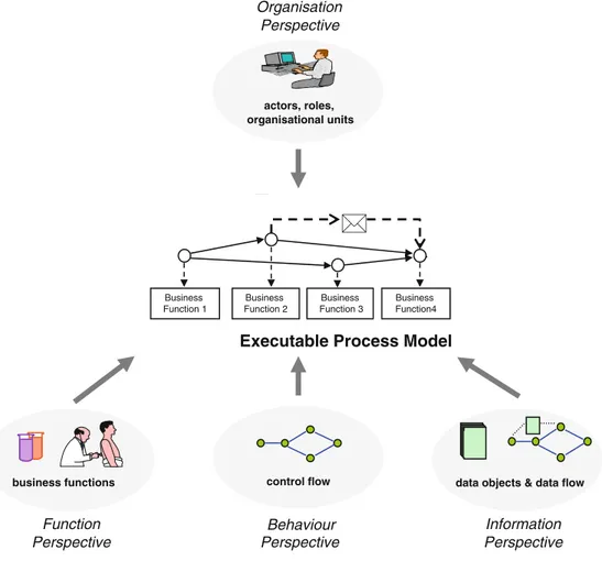
In deriving a business process model many different information and per-spectives of an organisation can be captured [85]. Among the others, the thesis focuses on: information related to the activities to be performed (func-tion perspective), who should perform them (organisa(func-tion perspective), when they should be performed and how they are organised in a flow (behaviour perspective) and finally which data are needed and produced (information perspective). These perspectives are shown in Figure 2.1 (that is a revised version of the figure in [2.4 Perspectives on a PAIS 85, Sec. 2.4]). 21
Business Function 1
...
Business
Function 2 Function 3Business Business Function4 Function nBusiness ...
business functions Function Perspective
Executable Process Model
control flow
Perspective
data objects & data flow Information Perspective time constraints Time Perspective actors, roles, Perspective application services Operation Perspective
Fig. 2.6 Perspectives in a PAIS
support of these perspectives and their integration with executable process models are needed in order to offer the right business functions at the right time and to the right users along with the information and the application services needed. In the following, the different perspectives are presented in detail.
2.4.1 Function Perspective
The function perspective covers the functional building blocks from which activity-centric process models can be composed; i.e., atomic activities representing ele-mentary business functions as well as complex activities representing subprocess models. To be more precise, an atomic activity constitutes the smallest unit of work, i.e., a description of a business function that forms one logical step within an executable process model. Usually, atomic activities require human or machine
resources for their execution (cf. Example 2.7). In the former case, the activity
organisational units Behaviour Organisation 2.4 Perspectives on a PAIS 21 Business Function 1 ... Business
Function 2 Function 3Business Business Function4 Function nBusiness ...
business functions Function Perspective
Executable Process Model
control flow
Perspective
data objects & data flow Information Perspective time constraints Time Perspective actors, roles, Perspective application services Operation Perspective
Fig. 2.6 Perspectives in a PAIS
support of these perspectives and their integration with executable process models are needed in order to offer the right business functions at the right time and to the right users along with the information and the application services needed. In the following, the different perspectives are presented in detail.
2.4.1 Function Perspective
The function perspective covers the functional building blocks from which activity-centric process models can be composed; i.e., atomic activities representing ele-mentary business functions as well as complex activities representing subprocess models. To be more precise, an atomic activity constitutes the smallest unit of work, i.e., a description of a business function that forms one logical step within an executable process model. Usually, atomic activities require human or machine
resources for their execution (cf. Example 2.7). In the former case, the activity
organisational units
Behaviour Organisation
Figure 2.1: Business Process Perspectives [85, Sec. 2.4].
Considering the behaviour perspective, the dynamic behaviour of a process model comes into play. In this regard, it is necessary to verify that the busi-ness process model designed in the design phase works seamlessly. Analysis can be done to detect syntactic, structural and behavioural problems. This step constitutes the analysis phase in the business process life cycle. One
of its aim is to ensure correctness of the designed business process model, because an erroneous behaviour can cause high costs for the involved organi-sations and damage their reputation. In order to check for model correctness, the qualities a model has to exhibit have to be clearly defined. This step is highly recommended, and will be addressed in the thesis, to proceed with business process analysis and the other phases of the business process life cy-cle. This latter includes the enactment and execution phase (the execution of the business process by stakeholders) and the monitoring and improvement phase (the monitoring of the running business process instances in order to maintain the business process models updated respect to the reality), that are out of scope of this thesis.
2.2
Business Process Model and Notation 2.0
Many different languages and graphical notations have been proposed to represent business process models, differing both in the possibility to express aspects related to the organisation perspectives and in the level of formality used to define the elements composing the notation. BPMN 2.0 [68] is cur-rently acquiring a clear predominance, also thanks to its capability to close the gap between IT and business teams. It has been standardised by the Object Management Group (OMG) and it is now widely accepted both in industry and academia. Its first goal is to provide a notation that is readily understandable by all business users. This includes the business analysts that create the initial drafts of the processes to the technical developers re-sponsible for implementing the technology that will perform those processes. Business process models are expressed in business process diagrams. Each diagram consists of a set of modelling elements. These elements are parti-tioned into a core element set and a complete element set. In particular, the BPMN notation allows to design different kinds of diagrams: process, collab-oration, choreography and conversation diagrams. For a complete and de-tailed description of each BPMN diagram, please refer to the official BPMN Specification.1 The thesis focuses on process diagrams, which are used to represent processes within a single organisation, and on collaboration dia-grams, that model processes of different organisations exchanging messages and cooperating to reach a shared business goal.
Next sections describe the BPMN elements that will be considered in the thesis and then introduce a running example used to show the reader how to employ the BPMN notation and through the work as a running example to show the thesis results.
1BPMN Specification –
10 CHAPTER 2. BACKGROUND
2.2.1
BPMN Notation
This section illustrates the BPMN elements considered in this thesis which include: pools, activities, events, gateway, connecting edges and data objects. • Pools (Figure 2.2) are used to represent participants or organisations involved in the collaboration, and include details on internal process specifications and related elements. Pools are drawn as rectangles, and they usually have a name associated with, referring to the name of the organisation. BPMN allows to assign a multi-instance marker (three vertical lines) to a pool, representing multiple instances playing the same role.
Send Task Receive Task Collapsed Sub-Process
Message Edge Sequence Edge
Start Event Start Message Event
Start Events
Catch Intermediate
Message Event Throw Intermediate Message Event
Intermediate Events
End Event Terminate Event End Message Event End Events Data Object [state] Text Annotation Exclusive Gateway
(or XOR Gateway) (or AND Gateway)Parallel Gateway Inclusive Gateway(or OR Gateway) Event Based Gateway
O rg an isa tio n O rg an isa tio n Figure 2.2: BPMN Pools.
• Activities (Figure 2.3) are used to represent a specific work to be performed within a process. They can be atomic or non-atomic (com-pound) and are drawn as rectangles with rounded corners. A Task is an atomic activity which represents work that can not be interrupted. It can be also used to send (Send Task) and receive (Receive Task) messages. It can have a multi-instance marker (three vertical or hor-izontal lines) when several activity instances are needed. This means that an activity is performed many times with different data sets. A Sub-Process a self-contained, composite activity that can be broken down into smaller units of work. A sub-process is collapsed when the details of the sub-process are not visible in the Diagram. A “plus” sign in the lower-center of the shape indicates that the activity is a sub-process and has a lower-level of detail. The sub-sub-process is expanded when the details (a Process) are visible within its boundary.
Multi-Instance Sequential Task Multi-Instance Parallel Task Send Task Receive Task Collapsed Sub-Process Message Edge Sequence Edge
Start Event Start Message Event Start Events
Catch Intermediate
Message Event Throw Intermediate Message Event Intermediate Events
End Event Terminate Event End Message Event End Events Data Object [state] Text Annotation
Exclusive Split Gateway (or XOR-split Gateway)
Parallel Split Gateway (or AND-split Gateway)
Event Based Gateway Inclusive Split Gateway
(or OR-split Gateway) Task O rg an isa tio n O rg an isa tio n
Exclusive Join Gateway (or XOR-join Gateway)
Parallel Join Gateway (or AND-join Gateway)
Inclusive Join Gateway (or OR-join Gateway)
Figure 2.3: Considered BPMN Activities.
• Connecting Edges (Figure 2.4) are used to connect process elements inside or across different pools. Sequence Edges are solid connectors
used to specify the internal flow of the process, thus ordering elements in the same pool, while Message Edges are dashed connectors used to visualise communication flows between organizationsReceive Task Sequential TaskMulti-Instance2.
Collapsed Sub-Process
Message Edge Sequence Edge
Start Event Start Message Event
Start Events
Catch Intermediate
Message Event Throw Intermediate Message Event
Intermediate Events
End Event Terminate Event End Message Event End Events Data Object [state] Text Annotation
Exclusive Split Gateway
(or XOR-split Gateway) (or AND-split Gateway)Parallel Split Gateway Inclusive Split Gateway(or OR-split Gateway) Event Based Gateway Task O rg an isa tio n O rg an isa tio n
Exclusive Join Gateway
(or XOR-join Gateway) (or AND-join Gateway)Parallel Join Gateway Inclusive Join Gateway(or OR-join Gateway)
Figure 2.4: BPMN Connecting Edges.
• Events (Figure 2.5) are used to represent something that can hap-pen. An event can be a Start Event representing the point from which a process starts, an Intermediate Event representing something that happens during process execution, or an End Event representing the process termination. Events are drawn as circles. When an event is source or target of a message edge, it is called Message Event. Accord-ing to the different kinds of message edge connections, it is possible to distinguish between the following type of events.
– Start Message Event is a start event with an incoming message edge; the event element catches a message and starts a process. – Throw Intermediate Event is an intermediate event with an
out-going message edge; the event element sends a message.
– Catch Intermediate Event is an intermediate event with an incom-ing message edge; the event element receives a message.
– End Message Event is an end event with an outgoing message edge; the event element sends a message and ends a process. There is also a particular type of end event, the Terminate End Event, displayed by a thick circle with a darkened circle inside; it stops and aborts the running process - all the ongoing activities are aborted and the process is abnormally terminated.
2As a matter of terminology, Sequence Edge and Message Edge are referred in the
12 CHAPTER 2. BACKGROUND Multi-Instance Sequential Task Receive Task Sub-Process Message Edge Sequence Edge Start Event
Start Message Event
Start Events Catch Intermediate Message Event Throw Intermediate Message Event Intermediate Events End Event Terminate Event End Message Event End Events Data Object [state] Text Annotation
Exclusive Split Gateway
(or XOR-split Gateway) (or AND-split Gateway)Parallel Split Gateway Inclusive Split Gateway(or OR-split Gateway) Event Based Gateway Task O rg an isa tio n O rg an isa tio n
Exclusive Join Gateway
(or XOR-join Gateway) (or AND-join Gateway)Parallel Join Gateway Inclusive Join Gateway(or OR-join Gateway)
Figure 2.5: Considered BPMN Events.
• Gateways (Figure 2.6) are used to manage the flow of a process both for parallel activities and choices. Gateways are drawn as diamonds and act as either join nodes (merging incoming sequence edges) or split nodes (forking into outgoing sequence edges). It is possible also to express gateways with multiple incoming and multiple outgoing edges in BPMN. These gateways are called mixed gateways. Since two be-haviours ( split and join) are expressed by a single concept, best practice is not to use mixed gateways but to use a sequence of two gateways with the respective split and join behaviour instead. Different types of gateways are available.
Multi-Instance Sequential Task Parallel Task Send Task Receive Task Collapsed Sub-Process Message Edge Sequence Edge Start Event
Start Message Event
Start Events Catch Intermediate Message Event Throw Intermediate Message Event Intermediate Events End Event Terminate Event End Message Event End Events Data Object [state] Text Annotation
Exclusive Split Gateway
(or XOR-Split Gateway) (or AND-Split Gateway)Parallel Split Gateway
Event Based Gateway Inclusive Split Gateway
(or OR-Split Gateway) Task O rg an isa tio n O rg an isa tio n
Exclusive Join Gateway
(or XOR-Join Gateway) (or AND-Join Gateway)Parallel Join Gateway
Inclusive Join Gateway (or OR-Join Gateway)
Figure 2.6: Considered BPMN Gateways.
– An Exclusive Gateway (or XOR gateway) gives the possibility to describe choices. In particular, a XOR-Split gateway is used after a decision to fork the flow into branches. When executed, it activates exactly one outgoing edge. A XOR-Join gateway acts as a pass-through, meaning that it is activated each time the gateway is reached. A XOR gateway is drawn with a diamond marked with the symbol “ˆ”.
– A Parallel Gateway (or AND gateway) enables parallel execution flows. An AND-Split gateway is used to model the parallel ex-ecution of two or more branches, as all outgoing sequence edges are activated simultaneously. An AND-Join gateway synchronizes the execution of two or more parallel branches, as it waits for all incoming sequence edges to complete before triggering the outgo-ing flow. An AND gateway is drawn with a diamond marked with the symbol “`” .
– An Inclusive Gateway (or OR gateway) gives the possibility to select an arbitrary number of (parallel) flows. In fact, an OR-Split gateway is similar to the XOR-OR-Split one, but its outgoing branches do not need to be mutually exclusive. An OR-Join gate-way synchronizes the execution of two or more parallel branches, as it waits for all active incoming branches to complete before triggering the outgoing flow. An OR gateway is drawn with a diamond marked with the symbol “#”.
– An Event-Based gateway is used after a decision to fork the flow into branches according to external choice. Its outgoing branches activation depends on taking place of catching events. Basically, such events are in a race condition, where the first event that is triggered wins and disables the other ones. An event-based gateway is drawn with a diamond marked with the symbol “D” double rounded.
Notably, XOR and OR splitting gateways may have guard condi-tions in their outgoing sequence edges. The thesis considers both the case in which the decision on XOR-Split gateways is taken non-deterministically and the case where conditions are used to decide which edge to activate according to data values.
• Artefacts (Figure 2.7) are used to show additional information about a business process that “is not directly relevant for sequence flow or message flow of the process”, as the standard mentions. Each artefact can be associated with flow elements. There are different types of artefacts. Among these, the thesis takes into account data objects and text annotations.
Task Send Task Receive Task Sub Process Collapsed
Message Edge Sequence Edge
Start Event Start Message Event
Start Events Catch Intermediate Message Event Throw Intermediate Message Event Intermediate Events
End Event Terminate
Event End Message Event End Events Data Object [state] Text Annotation
– Data objects (Figure 2.8) represent information and material flow-ing in and out of activities. They are depicted as a document with the upper-right corner folded over, and linked to activities with a dotted arrow with an open arrowhead (called data association in BPMN). The direction of the data association is used to es-tablish whether a data object is an input or output for a given activity. Paper documents and electronic documents, as well as information on any type of medium can be represented by data objects. Sometimes data objects can refer to a state. Indicating data objects’ states is optional: it can be done by appending the name of the state between square brackets to a data object’s label. Different types of Data Objects are available, they are reported in the following.
∗ (i) The Data Object Collection element refers to multi-instance Data Objects; using this a designer can express the involvement of more than one Data Object.
∗ (ii) The Data Input element is used to express (external) input data, and it can be read by an activity.
∗ (iii) The Data Output element is used to express output data, and it can be generated by an activity.
∗ (iv) The Data Store element is used to express data that per-sist after the process instance finishes.
– Text Annotations are depicted as an open-ended rectangle encap-sulating the text of the annotation, and are linked to a process modelling element via a dotted line (called association). Text an-notations do not bear any semantics, thus they do not affect the flow of tokens through the process model.
Data Object Collection
Data Input Data Output
Data Store Data Object
Collection
Data Input Data Output
Figure 2.8: BPMN Types of Data Objects.
Finally, a key concept related to the BPMN process execution refers to the notion of token. The BPMN standard states that “a token is a theoretical concept that is used as an aid to define the behaviour of a process that is being performed” [68, Sec. 7.1.1]. A token is commonly generated by a start event, traverses the sequence edges of the process and passes through its elements enabling their execution, and it is consumed by an end event
PC C ha ir Review Managment Assign Paper R evi ew er Paper Received Prepare Review Submit Review Reviews Reviews Evaluation Prepare Acceptance Letter Prepare Rejection Letter Discuss Feedback Received Send
Feedback Send Results Decision Process Completed C on ta ct Au th or Review Request Feedback What is the decision? Reject Accept Borderline Letter Notification Paper Paper Review Receive and Combine Reviews Review Process Completed Review Notification Received Read Notification Notification Processed Evaluation
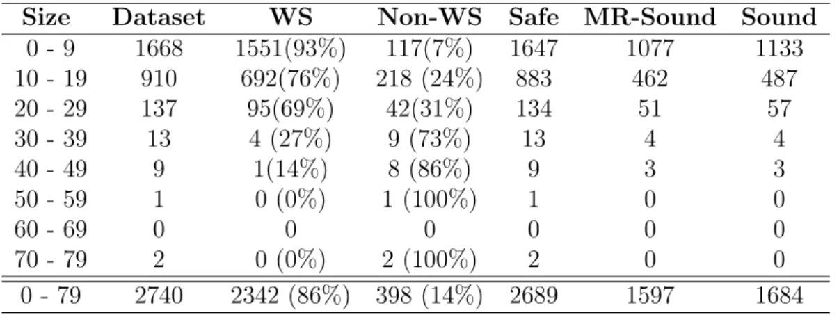
Figure 2.9: Paper Reviewing Collaboration Model.
when process completes. The distribution of tokens in the process elements is called marking, therefore the process execution is defined in terms of marking evolution. In the collaboration, the process execution also triggers message flows able to generate messages. They will be referred as message flow tokens.
2.2.2
Running Example
The business process diagram in Figure 2.9 shows the reader how to use the BPMN notation and will be used through the thesis as a running example. Note, it will be appropriately adapted according to the chapter’s focus.
It concerns the management of a single paper, which is revised by three reviewers; of course, the management of all papers submitted to the confer-ence requires to enact the collaboration for each paper. It is modelled in BPMN as a collaboration whose participants are: Program Committee (PC) Chair, the organiser of the reviewing activities, whose behaviour is represented by the process within the PC Chair pool (for the sake of sim-plicity, it is assumed that the considered conference has only one chair); Reviewer, a person with knowledge in some of the conference topics who performs the reviewing activity and, since more than one reviewer takes part in this, he/she is modelled as a process instance of a multi-instance pool; Contact Author, who submitted a paper to the conference and acts on behalf of the other authors (contact author).
The reviewing process is started by the PC Chair. This is reflected by the start event of the process at the PC Chair pool. The activity enacted first is the assignment of the paper to each reviewer (via a multi-instance sequential activity with loop cardinality set to 3 according to the number of involved reviewers for each paper). The paper is passed to the PC Chair process by means of a data input. After all reviews are received, and combined in the
Reviews data object, the chair starts their evaluation. According to the value of the Evaluation data object, the chair prepares the acceptance/rejection letter (stored in the Letter data object) or, if the paper requires further discussion, the decision is postponed. The decision behaviour is rendered via a data-based XOR-Split gateway. Discussion interactions are here abstracted and always result in an accept or reject decision. The chair then sends back a feedback to each reviewer, attaches the reviews to the notification letter, and sends the result to the contact author, via send tasks.
2.3
Relevant Business Process Properties
Ensuring correctness is crucial in the business process modelling field, because an erroneous behaviour can cause high costs for the involved organisations. This is especially important when considering collaboration diagrams, where many parties need to properly and quickly interact at the base of the models. To avoid undesired behaviours of BPMN models, modelling guidelines suggest to use structured building blocks [55]. This insight has triggered a stream of research on transforming unstructured models into structured ones. Informally, a process is well-structured if, for every element with multiple outgoing edges (a split), there is a corresponding node with multiple incoming edges (a join), such that the fragment of the model between the split and the join forms a single-entry-single-exit process component [44].
However, in some cases structuredness can only be achieved at the ex-pense of increased model size [32], or it cannot be applicable at all [74, 73]. When possible, it would anyway limit BPMN expressiveness and designer freedom [72]. Thus, the thesis considers models with arbitrary topology; this is necessary to enable a classification of both structured and unstructured models.
Regarding the considered properties, the thesis relies on a well-known class of properties in the domain of business process management, namely safeness [100] and soundness [104,99].
A BPMN process model is safe3, if during its execution no more than one token occurs along the same sequence edge. The notion of safeness is inspired by the Petri Net formalisation where it means that the Petri Net does not contain more than one token at each place in all reachable markings [100].
A BPMN process model is sound, if once its execution starts, it is always possible to reach a marking where either (i) each marked end event is marked by at most one token and there are no other tokens around, or (ii) all edges are unmarked. Thus, soundness requires the successful completion of the process execution. Also soundness is inspired by the BPM literature that
3Notably, the notion of safeness is different from that of safety; safeness is a standard
since the mid nineties presents several versions of soundness [100, 104, 99,
36]. The first soundness definition was provided by van der Aalst [96] in the context of workflow nets. However, this property can be applied to a wide range of process description languages either by transformation to workflow nets, if net-based formalisms are available [57], or by considering the corresponding execution semantics and checking the behaviour according to the model completion requirements.
There are other alternative notions of soundness described in the litera-ture, that motivated some results of the thesis. These notions strengthen or weaken some of the requirements mentioned in the already presented sound-ness definition, called classical soundsound-ness [104].
• k-soundness [104] focuses on the “option to complete” property, which requires that any running process instance must eventually complete. It is parametrized with a variable k which indicates the initial number of tokens in the source place.
• Weak soundness [104] for business processes was developed in the context of process choreographies. It disallows deadlocks (i.e. a mark-ing in which no transition is enabled), but it allows certain parts of the process not to participate in any process instance, that is it permits “dead activities”.
• Lazy soundness [80] relaxes weak soundness, because it allows ac-tivities to be executed after the final state has been reached; however, deadlocks are not permitted before the final state has been reached. Furthermore, the final node will be executed exactly once, while other nodes representing activities can still be or become executed. However, they must not trigger the final node again.
• Relaxed soundness [104] states that all activities of a business pro-cess participate in it (dead activity freedom) and each transition is contained in at least one sound firing sequence of the system.
• Easy soundness [104] requires that a final state is reachable from some initial states.
There are a lot of different properties definitions in the literature, referring to different process languages and even for the same process language (e.g. for EPC a soundness definition is given by Mendling [54], and for Workflow Nets van der Aalst [104] provides two equivalent soundness definitions). To escape from the jungle of definitions and aiming to capture the BPMN expressibility the thesis provides a uniform formal framework for BPMN collaboration diagrams that enables to give a precise formal characterisation of relevant properties of the domain.
2.4
Operational Semantics
Providing a formal semantics of informal languages is an essential step to clearly define the requirements a system has to satisfy. In this regard, process algebras are mathematically rigorous languages with well defined semantics that permit describing and verifying properties of concurrent communicating systems [66].
The basic component of a process algebra is its syntax, that defines what well-formed models are. Specifically, it is the combination of operators and more elementary terms. Many different approaches (operational, denota-tional, algebraic) can be used for describing the meaning of processes, that is to provide a semantics of the considered operators. However, the opera-tional approach has become the reference one. By relying on the so called Structural Operational Semantics (SOS), an operational semantics models a process as a labelled transition system (LTS), that consists of a set of states, a set of transition labels and a transition relation. The states of the transi-tion system are just process algebra terms while the labels of the transitransi-tions between states represent the actions or the interactions that are possible from a given state and the state that is reached after the action is performed by means of visible and invisible actions. Formally, an LTS is defined as follows. Definition 1 (Labelled Transition System). A labelled state transition sys-tem is a tuple pS, Σ, δq such that
• S is a finite set of states,
• Σ is a finite alphabet (i.e. a finite, non-empty set of symbols which refer to actions that a system can perform),
• δ Ă S ˆ Σ ˆ S is a state transition relation.
Inference systems are used to associate LTSs to process terms and are defined as follows.
• Inference Systems are a set of inference rule of the form p1, . . . , pn
q
where p1, . . . , pn are the premises and q is the conclusion. Each rule is interpreted as an implication: if all premises are satisfied then also the conclusion is inferred.
• Axiom is a rule without premises and it is written as
• Transition Rules represent transitions between states. In the case of operational semantics the premises and the conclusions will be triples of the form P `
Ý
Ñ Q and thus the rules for each operator op of the process algebras will be alike the one below, where ti1, . . . , imu Ď t1, . . . , nu and E1 i “ Ei when i R ti1, . . . , imu. Ei1 `1 ÝÑ Ei11 . . . Eim `m ÝÑ Eim1 oppE1, . . . , Enq ` Ý Ñ CrE11, . . . , E 1 ns
In the rule the target term Cr s indicates the new context in which the new sub terms will be operating after the reduction. Sometimes, these rules are enriched with side conditions that determine their applicabil-ity. Therefore, transition rules, given a term representing a state of the system, permit to determine the enabled actions and the corresponding reachable states, thus defining an LTS.
• Basic Actions represent the atomic (non-interruptible) step of a com-putation that is performed by a system to move from one state to the next. Actions represent various activities of concurrent systems, like sending or receiving a message, synchronizing with other processes etc. In process algebras two main types of atomic actions are considered, namely visible (or external) actions and invisible (or internal actions), the latter referred by the Greek letter τ.
BPMN Formalisation and
Correctness Properties
Chapter
3
Core BPMN Operational
Semantics
Providing a solid foundation to enable BPMN designers to understand their models in a consistent way is becoming more and more important. It is with the objective of reaching this goal that this thesis defines and exploits a formal characterisation of the collaborations’ semantics, specifically and directly given for BPMN models, to successively provide their classification. More specifically, it is provided an operational semantics to BPMN in the SOS style [71] by relying on the notion of LTS.
Notably, as shown in [64], even if the BPMN specification is quite wide, only less than 20% of its vocabulary is used regularly in designing business process models. Indeed, in this part of the thesis, only a core fragment of BPMN elements will be considered. However, it will be also shown how the proposed framework can be extended including other constructs (Part III).
In detail, this chapter reports the work regarding the definition of an Operational Semantics for the core BPMN notation. A running example is first presented (Section 3.1) to illustrate both the considered elements and the formal framework (Section 3.2).
Highlights. Distinctive aspects of the proposed semantics are:
1. it is a direct semantics, given in terms of features and constructs of BPMN, instead of an encoding into other formalisms (e.g. Petri Nets) as in most proposals in the literature;
2. it is specially given for collaboration diagrams, thus it focuses on ele-ments used for describing communications between different processes (e.g. message events, tasks and pools) that are usually not considered by other formalisations;
3. it is suitable to model both process and collaboration diagrams; 4. it refers to models involving processes with arbitrary topology, thus
overcoming the well-structuredness limitations.
3.1
Running Example
To introduce the core elements set, the business process model shown in Figure 3.1 is discussed. This collaboration diagram represents a modified version of the reviewing process for a scientific conference, which has been already introduced in Section 2.2.2. Since the goal of this example is to introduce the core elements, simplifications are in place. Specifically, the reviewing process usually involves many reviewers and many authors. For convenience, just one author and one reviewer are considered.
R evi ew er PC C ha ir Decision Process Completed Review Managment Assign Paper Acceptance Received Rejection Received Prepare Notification Letter Send Notification Paper Received Check Paper Quality Check Paper Novelty Send Rejection Review Send Acceptance Review Paper Rejected Paper Accepted Quality not okay Novelty not okay Quality okay Novelty okay C on ta ct Au th or Notification Received Read Notification Notification Processed Review Request Rejection Acceptance Notification
Figure 3.1: Paper Reviewing Collaboration Model.
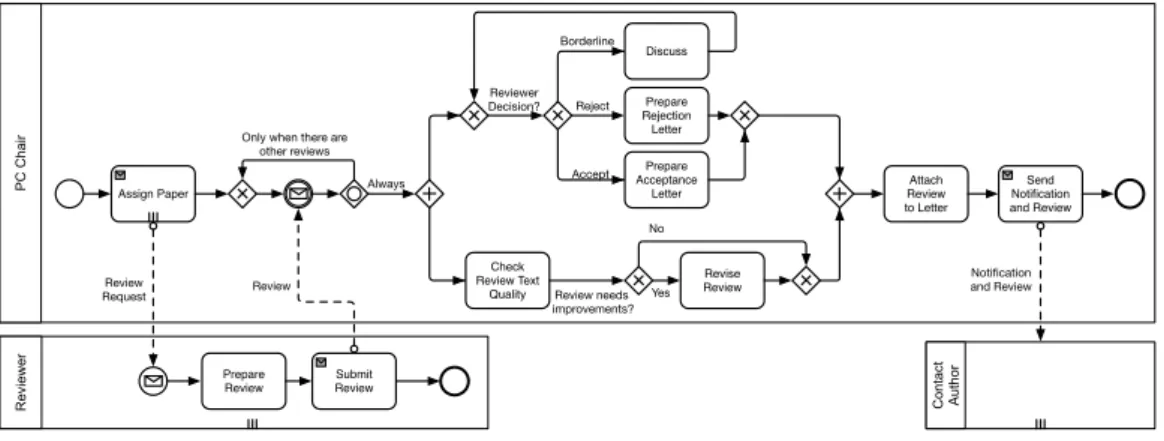
The program committee chairperson is the central role in the collabora-tion; this role is represented by the PC Chair pool. There are two additional roles involved, namely the Contact Author who submitted the research paper (the submission is omitted here) and waits for a notification and the Reviewerwho writes a rejection or acceptance review for the submitted pa-per, according to some requirements. Considering the Reviewer pool, from left to right we have that in order to decide the score of the paper, novelty and quality of the paper are checked in parallel, via an AND-Split gateway.
If the results of both checks are positive, the Reviewer sends an acceptance review to the PC Chair. If one of the check has a negative result (e.g. the paper lacks of novelty), the result of the other check is irrelevant, because the paper will be rejected anyway. Thus, as soon as one check provides a negative results, the Reviewer sends a rejection review to the PC Chair, com-pleting its activities by means of a terminate event which stops and aborts the running process, including the other check. Considering the PC Chair pool, after assigning the paper to the Reviewer, the PC Chair waits either for an acceptance review or for a rejection review. This behaviour is ren-dered by means of an event based gateway. Then, the PC Chair prepares the notification letter and sends it to the Contact Author, who can read and process it.
3.2
Formal Framework
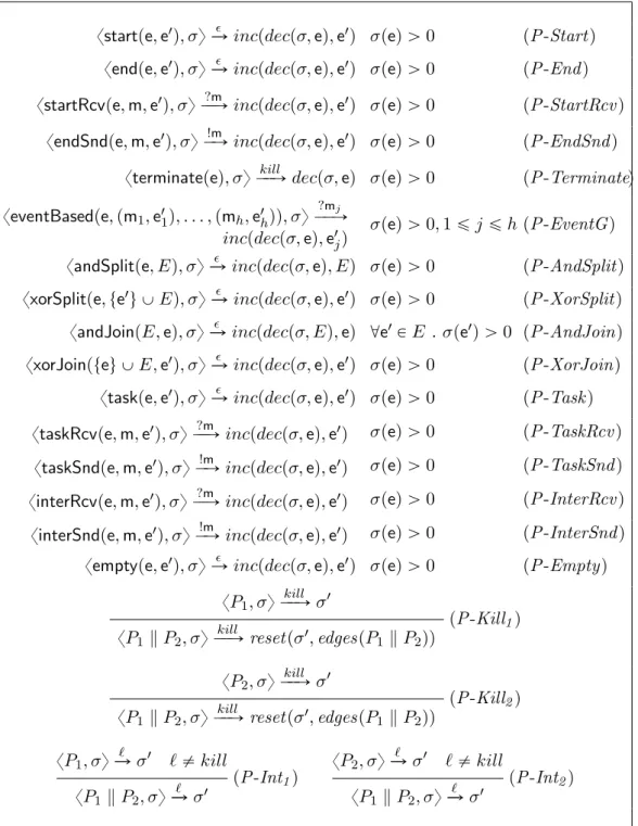
This section presents the BPMN formalisation. The proposed direct seman-tics is inspired by [21], but its technical definition is significantly different and its presentation is more compact and, hence, suitable for a formal study. In particular, configuration states are here defined according to a global per-spective. Specifically, the section first presents the syntax and operational semantics which have been defined for a relevant subset of BPMN elements.
3.2.1
Syntax
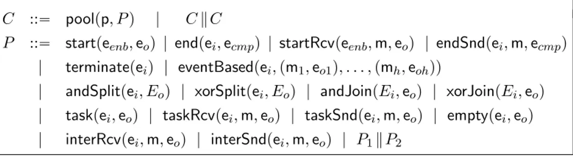
To enable the formal treatment of collaborations’ semantics, a BNF syntax of their model structure is defined (Figure 3.2). In the proposed grammar, the non-terminal symbols C and P represent Collaborations Structure and Processes Structure, respectively. The two syntactic categories directly refer to the corresponding notions in BPMN. The terminal symbols, denoted by the sans serif font, are the typical elements of a BPMN model, i.e. pools, events, tasks and gateways.
It is worth noticing that the syntax is too permissive with respect to the BPMN notation, as it allows to write collaborations that cannot be expressed
C ::“ poolpp, P q | C k C
P ::“ startpeenb, eoq | endpei, ecmpq | startRcvpeenb, m, eoq | endSndpei, m, ecmpq
| terminatepeiq | eventBasedpei, pm1, eo1q, . . . , pmh, eohqq
| andSplitpei, Eoq | xorSplitpei, Eoq | andJoinpEi, eoq | xorJoinpEi, eoq
| taskpei, eoq | taskRcvpei, m, eoq | taskSndpei, m, eoq | emptypei, eoq
| interRcvpei, m, eoq | interSndpei, m, eoq | P1k P2
in BPMN. Limiting such expressive power would require to extend the syntax (e.g., by imposing processes having at least one end event), thus complicating the definition of the formal semantics. However, this is not necessary in this work, as it is not proposing an alternative modelling notation, but it is only using a textual representation of BPMN models, which is more manageable for writing operational rules than the graphical notation. Therefore, the the-sis analythe-sis only considers terms of the syntax that are derived from BPMN models.
Intuitively, a BPMN collaboration model is rendered in this syntax as a collection of pools and each pool contains a process. More formally, a Collaboration C is a composition, by means of operator k of pools of the form poolpp, P q, where: p is the name that uniquely identifies the Pool; P is the Process included in the specific pool, respectively.
Notably, when considering the BPMN core set of elements it is not possi-ble to distinguish the difference between communicative tasks and interme-diate events (see Figure 3.3). This difference would be clear when extending the formal framework with data.
In the following, m P M denotes a message edge, enabling message ex-changes between pairs of participants in the collaboration, while M P 2M. Moreover, m denotes names uniquely identifying a message edge. Besides, e P E denotes a sequence edge, while E P 2E a set of edges; it is required |E| ą 1 when it is used in joining and splitting gateways. Similarly, an event-based gateway is required to contain at least two message events, i.e. h ą 1in each eventBased term. For the convenience of the reader, ei refers to the edge incoming in an element and eoto the edge outgoing from an element. In the edge set E, also spurious edges are included, denoting the enabled sta-tus of start events and the completed stasta-tus of end events, named enabling and completing edges, respectively. In particular, edge eenb, incoming to a start event, is used to enable the activation of the process, while ecmp is an edge outgoing from the end events suitable to check the completeness of the process. It is assumed that a unique sequence (resp. message) edge name is associated to each sequence (resp. message) flow in the BPMN model.
The correspondence between the syntax used here to represent a Process Structure and the graphical notation of BPMN is as follows.
• startpeenb, eoq represents a start event that can be activated by means of the enabling edge eenb and that has an outgoing edge eo.
• endpei, ecmpq represents an end event with an incoming edge ei and a completing edge ecmp.
• startRcvpeenb, m, eoq represents a start message event that can be acti-vated by means of the enabling edge eenb as soon as a message m is received and it has outgoing edge eo.
• endSndpei, m, ecmpqrepresents an end message event with incoming edge ei, a message m to be sent, and a completing edge ecmp.
• terminatepeiq represents a terminate event with incoming edge ei. • eventBasedpei, pm1, eo1q, . . . , pmh, eohqq represents an event based
gate-way with incoming edge ei and a list of possible (at least two) message edges, with the related outgoing edges that are enabled by message reception.
• andSplitpei, Eoq - resp. xorSplitpei, Eoq - represents an AND - resp. XOR - Split gateway with incoming edge ei and outgoing edges Eo. • andJoinpEi, eoq - resp. xorJoinpEi, eoq- represents an AND - resp. XOR
- Join gateway with incoming edges Ei and outgoing edge eo.
• taskpei, eoq represents a task with incoming edge ei and outgoing edge eo; there are also taskRcvpei, m, eoq- resp. taskSndpei, m, eoq- to consider a task receiving - resp. sending - a message m.
• interRcvpei, m, eoq (resp. interSndpei, m, eoq) represents an intermediate receiving - resp. sending - event with an incoming edge ei and an outgoing edge eo that are able to receive - resp. sending - a message m. • P1k P2represents a composition of elements in order to render a process
structure in terms of a collection of elements.
Moreover, to simplify the definition of well-structured processes (given later), an empty task is included in the syntax. It permits to connect two gateways with a sequence flow without activities in the middle.
In terms of collaboration, the correspondence between the syntax and the graphical BPMN notion is as follow.
• poolpp, P q represents a pool element with a pool name p. When acti-vated, the enclosed P behaves according to the elements it consists of, including nested process elements.
• C1k C2 represents a composition of elements in order to render a col-laboration structure in terms of a collection of elements.
To achieve a compositional definition, each sequence (resp. message) edge of the BPMN model is split in two parts: the part outgoing from the source element and the part incoming into the target element. The two parts are correlated since edge names in the BPMN model are unique.
Here in the following some auxiliary functions are defined on the collab-oration and the process structure. Considering BPMN collabcollab-orations they
may include one or more participants; function participantpCq returns the process structures included in a given collaboration structure. Formally, it is defined as follows.
participant pC1 k C2q “ participant pC1q Y participant pC1q participant ppoolpp, P qq “ tP u
To refer to the enabling edges of the start events of the considered process function startpP q is used.
start pP1 k P2q “ start pP1q Y start pP2q
start pstartpe, e1qq “ teu start pstartRcvpe, m, e1qq “ teu start pP q “ H for any element P ‰ startpe, e1
q or P ‰ startRcvpe, m, e1q Notably, it is assumed that each process in the collaboration has only one start event. Function startp¨q applied to C will return as many enabling edges as the number of involved participants.
start pC1 k C2q “ start pC1q Y start pC2q start ppoolpp, P qq “ start pP q
Similarly functions endpP q and endpCq are defined on the structure of pro-cesses and collaborations in order to refer to end events in the considered process.
end pP1 k P2q “ end pP1q Y end pP2q
end pendSndpe, m, e1qq “ te1u end pendpe, e1qq “ te1u
end pP q “ H for any element P ‰ endpe, e1q or P ‰ endSndpe, m, e1q Function endpCq on the collaboration structure is defined as follow.
end pC1 k C2q “ end pC1q Y end pC2q end ppoolpp, P qq “ end pP q
Function edgespP q refers the edges in the scope of P and edgesElpP q indicates the edges in the scope of P without considering the spurious edges (the formal definitions can be found in Appendix B).
Running Example 1. The BPMN model in Figure 3.1 is expressed in the syntax as the following collaboration structure (at an unspecified step of exe-cution):