1
2
3
4
The author would like to thank the following people for their contribution towards this project:
• Prof. Guido Danieli, my supervisor, for his guidance and help throughout the project, his steady hand, calm nature and wisdom without which I would have not reached this point;
• Prof. Maurizio Muzzupappa my thesis supervisor for his helpfulness and his assistance;
• Prof. Beno Benhabib for the opportunity to work in his lab and for his guidance in facing optimization problems;
• PhD Gianluca Gatti, for his assistance in understanding principles of robotics and his willingness.
• PhD Michele Perrelli and Sebastiano Meduri for their help in developing the electronic components of the system and the software.
• Diego Pulice and Renato Bentrovato of the Mechanical Departments Workshop for the manufacturing of the project parts.
• Staff of the Mesere Medical Centre for their assistance and the use of CT
scan system.
5
Contents
1. Introduction ... 12 1.1 Thesis Overview ... 12 1.2 Motivation ... 13 1.3 Biopsy Procedure ... 131.4 Computer Assisted Biopsy Procedure ... 16
1.5 Image-‐Guided Percutaneous Procedures ... 18
1.6 Rationale ... 26
2. Robotic System Overview ... 27
2.1 Direct Kinematic ... 30
2.2 Joint’s Architecture ... 34
2.3 End-‐Effectors ... 35
2.4 Electronic Control ... 37
2.5 Braking System Design ... 38
2.6 Brake Theoretical Analysis ... 40
2.7 Numerical Simulations and Testing ... 45
2.8 Navi-‐Robot Calibration ... 47
3. Computer Vision Theory ... 50
3.1 The Camera Projection Matrix ... 51
3.2 2D to 2D Case ... 52
3.3 The Direct Linear Transform Method (DLT) ... 52
3.4 3D to 2D Case ... 54
3.5 The Camera Model ... 55
3.6 Basic Pinhole Camera Model ... 56
3.7 Epipolar Geometry ... 58
3.8 Fundamental Matrix ... 60
3.9 Triangulation ... 61
4. Fluoroscopy Based Biopsy ... 61
4.1 C-‐Arm Fluoroscopy System Overview ... 62
4.2 Stereo Fluoroscopy ... 64
4.3 System Overview and Working Principle ... 66
4.4 Camera Calibration ... 70
4.5 Optical Navigator User Interface and Software ... 73
4.6 End-‐effector and Needle Orientation Determination ... 74
4.7 Targeting Computation ... 77
4.1 GUI Design and Operation ... 80
5. CT Based Biopsy ... 81
5.1 Graphical User Interface ... 82
5.2 Procedure Workflow for Registration Strategy I ... 83
5.3 Procedure Workflow for Registration strategy II ... 84
5.4 Targeting and Coordinate System Transformation ... 87
6
6.1 Laboratory Testing ... 89
6.2 Setup I: Calibration and Targeting ... 89
6.3 Optical Localizer Accuracy ... 90
6.4 Calibration Procedure Accuracy ... 92
6.5 Targeting ... 93
6.6 Setup II: Registration and Targeting ... 94
6.7 Error Propagation ... 97
7. Conclusions and Recommendations ... 98
7.1 Challenges, Future Improvements and Recommendations ... 98
7.2 Conclusion ... 99
Bibliography ... 101
List of Figures
Figure 1: Fine-needle aspiration ... 14Figure 2: Core-needle biopsy ... 14
Figure 3: Vacuum-assisted biopsy ... 15
Figure 4: Image-guided biopsy ... 15
Figure 5: Diagram of an image-guided robot-assisted percutaneous procedure ... 19
Figure 6: System by Stoianovici et al. [21] ... 21
Figure 7: Needle-guide by Radeka [22] ... 22
Figure 8: Device by Cadeddu et al. [23] ... 23
Figure 9: ROBOPSY™ system [24] ... 23
Figure 10: ultrasound-guided robotic system by Hong et al [30] ... 26
Figure 11: Navi-Robot schematic representation ... 27
Figure 12: Navi-Robot kinemtic model ... 28
Figura 13: four bar likages scheme ... 31
Figure 14: Joint’s architecture ... 34
Figure 15: CAD models of some of the end effectors for orthopedic procedures, being b the pointer, c and d the sawing guide, e the bone clamp, and f and g the drilling guides .... 36
7
Figure 16: End-effector needle holders ... 36
Figure 17: Needle’s cap for friction adjustment ... 37
Figure 18: brake system unlocked position ... 38
Figure 19: brake system locked position ... 38
Figure 20: Brake system assembly prototype ... 39
Figure 21: Braking current load ... 40
Figure 22: Brake's shoe geometry ... 41
Figure 23: Brake’s shoe pressure load ... 42
Figure 24: Brake’s shoe static equilibrium ... 44
Figure 25: Brake system multi-body cad model ... 45
Figure 26: Housing’s velocity during braking ... 46
Figure 27: Brake system experimental test ... 47
Figure 28: Navi-Robot prototype ... 48
Figure 29: Navi-Robot calibration setup ... 49
Figure 30: Basic pinhole camera model ... 56
Figure 31: Epipolar geometry ... 59
Figure 32: C-arm fluoroscopy system’s elements ... 62
Figure 33: Optical coupling system ... 63
Figure 34: C-arm fluoroscopy system setup ... 64
Figure 35: stereovision fluoroscopy ... 65
Figure 36: C-arm Fluoroscopy system calibration ... 67
Figure 37: Biopsy procedure fluoroscopy based setup ... 70
Figure 38: Calibration ring template ... 72
Figure 39: Optical navigator user interface ... 74
8
Figure 41: Needle system coordinate reconstructed ... 76
Figure 42: Needle path planning ... 78
Figure 43: Rotation angles and planes ... 79
Figure 44: C-arm fluoroscopy system user interface ... 81
Figure 45: CT scan user interface ... 82
Figure 46: Biopsy procedure CT based setup ... 84
Figure 47: Biopsy procedure CT based setup using registration strategy II ... 86
Figure 48: Optical marker (left) F-cam calibration setup (right) ... 90
Figure 49: known distances between marker ... 91
Figure 50: Needle targeting procedure ... 94
Figure 51: CT scan of the rigid object simulating the patient ... 95
Figure 52: Registration strategy ... 96
List of Tables
Table 1: Navi-Robot geometric parameters ... 29Table 2: Navi-Robot D-H parameters ... 29
Table 3: Optical navigator accuracy results ... 91
Table 4: Calibration accuracy result ... 92
Table 5: F-cam accuracy result ... 93
Table 6: F-cam based targeting accuracy result ... 94
9
10
Abstract
The goal of this research is the development of a robotic system for needle biopsy guidance under fluoroscopy and computed tomography (CT). The system aims to minimize patient-surgeon radiation exposure, achieving more accurate biopsy diagnosis, lower patient discomfort, and shorter procedure time. Currently, needle biopsy is performed by free-hand passage of the biopsy needle from the skin surface to the area that must be analyzed. The main problem with free-hand method is the limited accuracy when initially the biopsy needle must be aligned, when the planned needle trajectory must be followed and finally, when the physician releases the needle that can drift or tilt away from the desired path due to gravity, particularly when first starting the insertion. Additionally, direct irradiation to the hand of the physician has been considered to be a disadvantage of this modality, since it can result in high cumulative effective doses of radiations.
The robotic system used in this project to guide the needle is the Navi-Robot, a 6-degree of freedom (DoF) hybrid parallel/serial prototype of robot provided by a novel braking system, which was design and manufactured during this study, to allow the robot working both as measurement device and as robot. The first topic investigated in this research was performing a fluoroscopy-based biopsy procedure using the Navi-Robot. To this end, a stereovision setup was built and calibrated using a single camera simulating a C-arm fluoroscopy system, an optical localizer and the relative software as well as a graphical user interface. The system, implementing the stereovision theory, allows reconstructing the 3D locations of the needle entry point and the target point selected by the surgeon in the fluoroscope image space. Thus, performing a registration procedure, or rather a coordinates transformations, the 3D coordinates are mapped from the image space to the robot space and the desired needle path as well as the depth of penetration are calculated. Finally, the
11
position and the orientation of the end-effector carrying the needle-guide is adjusted accordingly, allowing the surgeon inserting the needle until the calculated depth is reached. The second topic investigated was performing a CT based biopsy procedure using the Navi-Robot. To achieve this goal was necessary to register the coordinates of the needle entry point and of the target from the CT space to the robot space. Using rigid marker placed on a phantom simulating the patient two different strategies for registration were tested: the first one was performed using the Navi-Robot as measurement system and its end-effector as a touch probe to localize the markers; the second strategy was implemented providing the end-effector by optical markers and using an optical localizer to track both the marker on the phantom and the marker on the end-effector. Once the registration was performed, the desired needle path was computed to adjust the needle-guide of the robot allowing the surgeon inserting the needle. Simulating the C-arm fluoroscopy system with a digital camera, needle placement accuracies of 10 mm was achieved within the calibrated volume. Using CT images and the optical localizer for the registration procedure, needle placement accuracies of 4 mm was achieved, while using the robot for the registration procedure an accuracy of 2 mm was obtained in the simulated environment.
12
1. Introduction
1.1 Thesis Overview
Chapter 1 presents background on biopsy techniques. Relevant needle-positioning systems developed during the last decade are discussed. Chapter 2 describes the Navi-Robot, the prototype robotic system used to position the needle-guide, as well as its main components and working principle. Moreover, it discusses a novel braking system designed and tested for the robot prototype. Chapter 3 describes the theory implemented to mathematically describe cameras and use them for relative positioning. This leads to Chapter 4 where the elements of the system used to perform a needle biopsy using the robotic system under C-arm fluoroscopy guidance are described. It also depicts the calibration techniques used to implement the stereovision using a single camera and the reasons for their use in the project. This chapter also covers the mathematical computations implemented to rotate and translate the needle-guide for accurate targeting and description of the graphical interface developed for the procedure. In Chapter 5, the procedure used to guide a needle biopsy with the Navi-Robot under CT is shown as well as the software to localize the markers used for the registration procedure, or rather to map the coordinates of the target point from the CT-space to the robot space. Chapter 6 describes the experiments setup and reports on the results obtained. The final chapter presents the conclusions and recommendations of the project. The shortcomings of the designed system are also commented on.
13
1.2 Motivation
Increased use of intraoperative fluoroscopy exposes the surgeon to significant amounts of radiation. The average yearly exposure of the public to ionizing radiation is 360 millirems (mrem), of which 300 mrem is from background radiation and 60 mrem from diagnostic radiographs. A chest radiograph exposes the patient to approximately 25 mrem and a hip radiograph to 500 mrem. A regular C-arm exposes the patient to approximately 1,200 to 4,000 mrem/min. The surgeon may receive exposure to the hands from the primary beam and to the rest of the body from scatter. Recommended yearly limits of radiation are 5,000 mrem to the torso and 50,000 mrem to the hands. Exposure to the hands may be higher than previously estimated, even from the mini C-arm [1].
Needle biopsy is one of the intraoperative procedures that mainly cause a large amount of ionizing radiation absorption when is performed using the free-hand method. Performing a biopsy in fact requires the physician first to adjust the biopsy needle by hand, then to partially insert it towards the target, finally to proceeds with further insertion of the needle, checking its position by scanning the area as necessary.
Potential decreases in radiation exposure and increase in accuracy can be accomplished by using instruments such as robot or positioning systems. These tools have the potential to improve the precision and capabilities of the physicians during surgical procedures. Therefore, a robotic system able to work with as many as possible diagnostic imaging equipment such as: CT-scan, ultrasound, fluoroscopy, MRI, etc., would have a great impact on the surgery scenario.
1.3 Biopsy Procedure
During a needle biopsy, the surgeon uses a special needle to extract cells from a suspicious area. A needle biopsy is often used on tumors that the doctor can
14
feel through your skin, such as suspicious breast lumps and enlarged lymph nodes. When combined with an imaging procedure, such as X-ray, needle biopsy can be used to collect cells from a suspicious area that can't be felt through the skin. Needle biopsy procedures include:
• Fine-needle aspiration. During fine-needle aspiration, a long, thin needle is inserted into the suspicious area. A syringe is used to draw out fluid and cells for analysis.
Figure 1: Fine-needle aspiration
• Core needle biopsy. A larger needle with a cutting tip is used during core needle biopsy to draw a column of tissue out of a suspicious area.
15
• Vacuum-assisted biopsy. During vacuum-assisted biopsy, a suction device increases the amount of fluid and cells that is extracted through the needle. This can reduce the number of times the needle must be inserted to collect an adequate sample.
Figure 3: Vacuum-assisted biopsy
• Image-guided biopsy. Image-guided biopsy combines an imaging procedure, such as X-ray, computerized tomography (CT), magnetic resonance imaging (MRI) or ultrasound, with a needle biopsy. Image-guided biopsy allows your doctor to access suspicious areas that can't be felt through the skin, such as abnormalities on the liver, lung or prostate. Using real-time images, the doctor can make sure the needle reaches the correct spot.
16
One of the more difficult initial decisions is selecting the biopsy site. Generally, lesions with the most advanced inflammatory changes should be chosen; evolutionary changes may take several days and a too-early biopsy may reveal only nonspecific features. For blistering diseases, the reverse is true; the earlier the lesion, the more specific the histopathology. Consequently, only the newest vesicles and blisters should be biopsied, usually within 48 hours of their appearance.Older lesions with secondary changes such as crusts, fissures, erosions, excoriations, and ulcerations should be avoided since the primary pathological process may be obscured. For non-bullous lesions, the biopsy should include maximal lesion skin and minimal normal skin [2].
1.4 Computer Assisted Biopsy Procedure
A number of modern clinical practices involve percutaneous (“through the skin”) diagnosis and local therapies, where a tubular device (needles, catheters, tissue ablation probes, etc.) has to be inserted deep into soft tissue to reach a target. There are several applications for percutaneous needle insertion such as biopsies [3], regional anesthesia, blood sampling [4], neurosurgery [5] and brachytherapy [6]. The effectiveness of a treatment and the success or precision of a diagnosis is highly dependent on the accuracy of percutaneous insertion [7]. There is not a defined tolerance for the accuracy of needle insertion in clinical practice and in general, insertions with less needle misplacement result in more effective treatment [8] or increase the precision of diagnosis. The desired performance depends on the application. In procedures such as biopsy (for prostate, kidney, breast and liver), brachytherapy and anesthetic, placement accuracy of millimeters is desirable while in brain, fetus, eye and ear procedures placement accuracy of micro-millimeter is preferable. Clinical studies have revealed that targeting error (needle misplacement) may be due to imaging limitations, image misalignments, target uncertainty, human errors, target movement due to tissue deformation and needle deflection [9]. In Ref.
17
[9], for imaging misalignment of ±5 mm in only one view, a targeting error of about 10 mm was calculated. Furthermore, in a percutaneous procedure, the target might be in the millimeter neighborhood of another organ, vessel or nerve. Therefore, extra caution is required to avoid any damage or spread of a disease, which in turn may lead to subsequent complications (e.g., seed migration) that may even be fatal [10]. Some of the desired accuracies may be achieved using current tools and models but accurate needle placement for many other applications requires much more research and development. Real-time visualization and high precision imaging techniques can increase the performance of the surgeon in navigating the tool and tracking the target [11]. Advanced mechanical tools that consider the constraints imposed by anatomy using haptic feedback and those that reduce or remove human errors due to fatigue, hand tremor and problems in hand/eye coordination can con- tribute to reduction in targeting error [12]. Medical simulators that can accurately model a clinical procedure are of great advantage for training medical residents, predicting the out-come of complex procedures and practicing new procedures. Percutaneous therapies are constrained procedures where target visibility, target access and tool maneuverability in addition to physiological changes to the target are key issues. During some conventional needle insertion procedures, the surgeon relies on kinesthetic feedback from the tool (needle or catheter) and his or her mental 3D visualization of the anatomical structure [13]. Real-time imaging techniques that are used in some procedures can improve target visibility. However, human errors [10], imaging limitations, target uncertainty [9], tissue deformation and needle deflection [14] are a few known problems that contribute to needle misplacement in percutaneous procedures. Human errors may be related to poor techniques and insufficient skills of a physician. Target uncertainty may be caused by patient motion, physiological or geometry related problems [9]. Despite the availability of different imaging modalities to improve visualization; there are several factors such as high cost, poor resolution, probe availability, X-ray exposure, material compatibility, reliable
18
real-time image processing techniques, etc. that may limit application of imaging in some clinical and research studies. A few examples of these limitations are working with robots where MRI is the imaging modality (magnetic interference), using artificial phantoms when the imaging modality is ultrasound (acoustic properties), and using camera when performing ex vivo experiments (non- visibility of target). Needle deflection is generally due to the bevel tip and diameter of the needle [15]. The tissue, into which the needle is inserted, may also contribute to needle deflection. The factors that affect tissue deformation include mechanical properties of soft tissue, the contact force of the needle tip, and frictional forces between the tissue and the needle shaft [16]. Other causes of inaccuracy in percutaneous therapies are physiological changes in the organ between the planning and treatment phases, glandular swelling during the operation. In addition, difference in tissue types involved in each procedure, differences in mechanical properties of healthy and diseased tissue, changes of mechanical properties when tissue is damaged and variability of soft tissue properties for the same organ in different patients.
1.5 Image-Guided Percutaneous Procedures
To date, a number of researchers have explored ways to improve the process of needle insertion in soft tissue using robotics and medical imaging in order to improve the accuracy of the procedure.
19
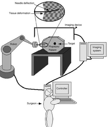
Figure 5: Diagram of an image-guided robot-assisted percutaneous procedure
Fig. 5 shows a schematic diagram of an image-guided robot-assisted percutaneous procedure. Some of these techniques, such as CT and MRI, are overly expensive and can only be implemented in highly equipped facilities. Techniques also exist that are used for keeping the object at the correct position and alignment during insertion. Rigid aligning and laser-guided methods are the most common.
Initial applications of robots in urologic surgery have demonstrated their potential in aiding surgeons. The chief advantages of robotic manipulation of surgical tools are accurate registration of medical images, consistent movement free of fatigue or tremor, the ability to work in environments unfriendly to surgeons, and the ability to position instruments quickly and accurately.
Surgical robots can be divided into two categories: surgeon driven systems and image-guided systems. Surgeon driven systems rely directly on the surgeon‘s movement and simulate that movement by robotic means. Image-guided
N. Abolhassani et al. / Medical Engineering & Physics 29 (2007) 413–431 415 assisted needle insertion system for prostate biopsy and
ther-apy with intraoperative CT guidance. Schneider et al.[40]
presented a robotic device for transrectal needle insertion into the prostate with integrated ultrasound. Ebrahimi et al.
[41]introduced a hand-held steerable device which incorpo-rates a pre-bent stylet inside a straight cannula, and Maurin et al.[42]presented a parallel robotic system for percuta-neous procedures under CT guidance. Hong et al.[43]built an ultrasound-guided needle insertion robot. Their robot has a 5-DOF passive arm for positioning the needle at the skin entry point and 2-DOF for insertion. They developed a real-time image servo system to compensate for tissue deformation and organ movement.
1.4. Scope of this review
Fig. 2shows different stages during the needle insertion procedure as reviewed in this paper. Studies that are reviewed have in general been undertaken to improve both manual and robotic percutaneous procedures. When a needle is inserted percutaneously, visual and haptic feedback are required to enhance the clinical operation. Visual and haptic data provide knowledge about tissue deformation and needle
deflection during the needle insertion procedure and are useful in modeling. Visual data can also be processed and used in image-guided procedures. The models obtained from visual and haptic data can be used for intraoperative path planning and trajectory generation and they can also be used for better off-line planning and simulation for medical training. For deep needle insertion, knowledge of anatomical structures is also a requirement. In manual procedures, the knowledge and expertise can be integrated with visual feedback from an imaging modality to guide the needle with a limited accuracy. In robotic procedures, imaging data is incorporated with precise robotic motion and accurate prediction of needle deflection and tissue deformation to increase the accuracy of the overall procedure.
This paper is intended to give an overview of recent non-clinical work in the field of needle insertion in soft tissue with a focus on the effect of force measurements for modeling the needle–tissue interaction and on guiding robots to improve the precision of needle insertion (shaded area inFig. 2). Knowing interaction forces and developing appropriate nee-dle deflection and tissue deformation models during neenee-dle insertion are the key issues for accurate insertion. This paper reviews those studies that implicitly improve the needle
20
systems use a target specified by the surgeon to manipulate instruments in such a way as to reach the specified target. As the system developed in this project fall in the latter category, the focus will be on current image-guided systems applied in surgery.
In 2003, Stoianovici et al. [17] described the development of a robot for radiological percutaneous interventions using computed tomography (CT) for needle biopsy, radio frequency ablation, cryotherapy, and other needle procedures. The system called “AcuBot” is a compact six-degree-of-freedom robot for manipulating a needle or other slender surgical instrument in the confined space of the imager without inducing image artifacts.
In 1994, Potamianos et al. [18] investigated a robotic system to assist the urologist in obtaining intraoperative percutaneous renal access. The system utilized a passive manipulator mounted on the operating table, guided by a C-arm fluoroscopic unit. Registration between the manipulator and C-C-arm coordinate systems was completed by a personal computer that also displayed the access needle‘s trajectory on each fluoroscopic image. The surgeon could then manipulate the robotic arm until the needle‘s anticipated trajectory aligned with the target calyx. Experiments evaluated system performance with a targeting accuracy of less than 1.5 mm. The system developed by Bzostek et al. [19] differed mainly from Potamianos‘design in that it used an active robot to manipulate the needle and used bi-planar instead of C-arm fluoroscopy. This system achieved in-vitro accuracy results of 1 mm. Ex-vivo tests on porcine kidneys resulted in an 83% insertion success rate. In-vivo tests on cadaveric porcine and live percutaneous renal access resulted in a 50% success rate with needle deflection, bowing, and rib interference stated as the main problems. This system consisted of a three degree of freedom robot with a needle injector end-effector. Calibration and distortion correction was done after which robot to image-space registration was completed.
Rovetta developed another image-guided robotic system that has been evaluated clinically [20]. This system used external video cameras and TRUS
21
(trans-rectal ultrasonography) for robot registration. Stoianovici et al. developed a manual system that mimicked and improved on the standard technique used by the urologist during a percutaneous procedure. Similar to the manual surgical technique as keyhole surgery, the skin insertion site, target calyx and needle was superimposed as a single point in a C-arm fluoroscopic image. The needle was held by a novel mechanism driven by a joystick controlled variable speed DC motor enabling automatic needle insertion. The device was locked so the C-arm could be rotated freely to the lateral view. The advantages of this system were that it did not require computer-based vision or a fully actuated robotic system. Accuracies obtained were claimed to be better than that of the standard procedure [21].
Another needle guidance application was that of Radeka, who used CT- guidance and a needle alignment device to position the access needle inside a specified calyx. Bio modeling for pre-surgery planning was performed prior to the access procedure. In fifteen of the seventeen patients, needle placement was performed successfully with the first attempt [22]. The needle alignment device and its exploded view are shown in Fig 6.
Figure 6: System by Stoianovici et al. [21]
LITERATURE REVIEW AND RATIONALE
16
needle was superimposed as a single point in a C-arm fluoroscopic image. This system is shown in Figure 2-10. The needle was held by a novel mechanism driven by a joystick controlled variable speed DC motor enabling automatic needle insertion. The device was locked so the C-arm could be rotated freely to the lateral view. The advantages of this system were that it did not require computer-based vision or a fully actuated robotic system. Accuracies obtained were claimed to be better than that of the standard procedure [33].
Another needle guidance application was that of Radecka, who used CT-guidance and a needle alignment device to position the access needle inside a specified calyx. Bio-modeling for pre-surgery planning was performed prior to the access procedure. In fifteen of the seventeen patients, needle placement was performed successfully with the first attempt [34]. The needle alignment device and its exploded view are shown in Figure 2-11(a)-(b).
Figure 2-10: System by Stoianovici et al.[33]
(a) Assembled view (b) Exploded view
22
Figure 7: Needle-guide by Radeka [22]
Cadeddu and associates improved on Stoianovici‘s original design. A mechanical system for percutaneous access called PAKY (Percutaneous Access to the Kidney), which is a mechanical stereotactic frame and actuated needle system that can be used as a platform for needle placement, was developed. Superimposed fluoroscopic images of the target, access point and needle were used to align the needle by adjusting the orientation of the C-arm imaging system. Clinical percutaneous access was attained in each of the nine evaluated cases [23]. This system is shown in Fig 8.
Another study is that of the Robopsy TM system, a tele-operated, patient-mounted, disposable needle guidance and insertion system. This system‘s function is the assistance of radiologists in performing minimally invasive percutaneous biopsies under CT guidance.
LITERATURE REVIEW AND RATIONALE
16
needle was superimposed as a single point in a C-arm fluoroscopic image. This system is shown in Figure 2-10. The needle was held by a novel mechanism driven by a joystick controlled variable speed DC motor enabling automatic needle insertion. The device was locked so the C-arm could be rotated freely to the lateral view. The advantages of this system were that it did not require computer-based vision or a fully actuated robotic system. Accuracies obtained were claimed to be better than that of the standard procedure [33].
Another needle guidance application was that of Radecka, who used CT-guidance and a needle alignment device to position the access needle inside a specified calyx. Bio-modeling for pre-surgery planning was performed prior to the access procedure. In fifteen of the seventeen patients, needle placement was performed successfully with the first attempt [34]. The needle alignment device and its exploded view are shown in Figure 2-11(a)-(b).
Figure 2-10: System by Stoianovici et al.[33]
(a) Assembled view (b) Exploded view
23
Figure 8: Device by Cadeddu et al. [23]
Figure 9: ROBOPSY™ system [24]
This system enables radiologists to automatically adjust needle alignment and LITERATURE REVIEW AND RATIONALE
17
Cadeddu and associates improved on original design. A mechanical system for percutaneous access called PAKY (Percutaneous Access to the Kidney), which is a mechanical stereotactic frame and actuated needle system that can be used as a platform for needle placement, was developed. Superimposed fluoroscopic images of the target, access point and needle were used to align the needle by adjusting the orientation of the C-arm imaging system. Clinical percutaneous access was attained in each of the nine evaluated cases [35]. This system is shown in Figure 2-12.
A pending US patent, depicted in Figure 2-13
a teleoperated, patient-mounted, disposable needle guidance and insertion system. the assistance of radiologists in performing minimally invasive percutaneous biopsies under CT guidance.
Figure 2-12: Device by Cadeddu et al. [35]
LITERATURE REVIEW AND RATIONALE
18
Figure 2-13: ROBOPSY system [36]
This system enables radiologists to automatically adjust needle alignment and insert the needle without removing the patient from the CT scanner. No automatic needle positioning calculations are done. The needle is adjusted remotely by the surgeon under continuous CT guidance to confirm when correct angular alteration has been completed. Testing of this system is still ongoing [36].
Vaird et al. developed a MRI needle guidance technique where the target point inside the body and the access point on the skin are defined on MRI images, thus defining the required needle trajectory. 3D imaging is used for target visualization, insertion planning and validation of the roadmap. Monochromic CCD (charge coupled device) cameras sensitive to infrared radiation are used in a stereovision setup to determine needle orientation. Current needle orientation relative to the planned needle orientation is then monitored in near real-time during insertion, thus aiding the surgeon in accurate needle placement. Obtained accuracy was 3 mm [37].
Navab et al. presented an approach for fluoroscopy image-based guidance of a surgical tool towards multiple targets from fixed or variable entry points. The method is based on visual servoing and required no prior calibration or registration. At least 12 images are required for each targeting sequence [38]. A US Patent by Geiger and Navab describes a method by which a biopsy needle is aligned with a target using needle markers from two fluoroscopic images taken in orthogonal C-arm positions. Needle alignment angles are calculated by a computer system in a two-step procedure, where the first alignment angle is computed and set with the C-arm in position 1, and the second alignment angle is computed and set with the C-arm in position 2 [39].
Another US Patent by Peter and associates describes a system for defining the location of a medical instrument relative to features of a medical workspace including a patient's body region. Pairs of two-dimensional images, obtained by two video cameras making images of the workspace along different sightlines which intersect, are used. A calibration structure is used to define a three dimensional coordinate framework. Appropriate image pairs are used to locate
24
insert the needle without removing the patient from the CT scanner. No automatic needle positioning calculations are done. The surgeon under continuous CT guidance to confirm when correct angular alteration has been completed adjusts the needle remotely [24]. Vaird et al. developed a MRI needle guidance technique where the target point inside the body and the access point on the skin are defined on MRI images, thus defining the required needle trajectory. 3D imaging is used for target visualization, insertion planning and validation of the roadmap. Monochromic CCD (charge-coupled device) cameras sensitive to infrared radiation are used in a stereovision setup to determine needle orientation. Current needle orientation relative to the planned needle orientation is then monitored in near real-time during insertion, thus aiding the surgeon in accurate needle placement. Obtained accuracy was 3 mm [25].
Navab et al. presented an approach for fluoroscopy image-based guidance of a surgical tool towards multiple targets from fixed or variable entry points. The method is based on visual servoing and required no prior calibration or registration. At least 12 images are required for each targeting sequence [26]. A US Patent by Geiger and Navab describes a method by which a biopsy needle is aligned with a target using needle markers from two fluoroscopic images taken in orthogonal C-arm positions. Needle alignment angles are calculated by a computer system in a two-step procedure, where the first alignment angle is computed and set with the C-arm in position 1, and the second alignment angle is and track any other feature such as a medical instrument in the workspace with the cameras fixed in their positions relative to the workspace [27].
An additional US Patent by Regn describes CT apparatus equipped with a laser device marking a guide path on a patient for a medical instrument to be used in a medical procedure such as needle puncturing. The CT apparatus produces a planning image and a guide path is identified within the planning image. A computer, using the planning image, and the path identified, automatically adjusts the position of a light source. If necessary a table, on which a patient is
25
supported, is positioned so that a beam from the light source is positioned to coincide with the guide path identified on the image. During insertion, the needle is kept in this line of light by the surgeon, thus targeting the defined position [28]. The main problems incurred by most of the mentioned techniques are needle deflection due to tissue resistance and target movement. Techniques that consider these factors are currently being researched. It was not within the scope of this project to take these factors into account, but to verify whether accurate and operationally viable targeting results could be obtained by implementing stereovision theory on fluoroscopic images computed and set with the C-arm in position and also to validate a system able to operate even with CT or other medical imaging systems.
Another US Patent by Peter and associates describes a system for defining the location of a medical instrument relative to features of a medical workspace including a patient's body region. Pairs of two-dimensional images, obtained by two video cameras making images of the workspace along different sightlines, which intersect, are used. After the calibration image pair is made, the fiducial structure is removed. A standard projection algorithm is used to reconstruct the 3D framework of the fiducial structure from the calibration image pair. Appropriate image pairs can then be used to locate and track any other feature such as a medical instrument, in the workspace, so long as the cameras remain fixed in their positions relative to the workspace. The computations are desirably performed with a computer workstation including computer graphics capability, image-processing capability, and providing a real-time display of the workspace as imaged by the video cameras [29].
Hong et al developed a real-time ultrasound-guided needle-insertion medical robot for percutaneous cholecystectomy. The instrument uses intraoperative images and modifies the needle path in real time by using a novel ultrasonic image segmentation technique [30].
26
Figure 10: ultrasound-guided robotic system by Hong et al [30]
1.6 Rationale
Despite the number of apparent solutions described, only few of the techniques described are currently used in practice, mainly due to their high cost. Each of them, in fact, has been designed to work with a specific medical imaging apparatus or surgical tools. The robotic system proposed, originally designed to perform orthopedic and laparoscopic surgical procedures, is able to guide the needle or other surgical tool, to the correct insertion depth with minimal radiation exposure to the patient and surgery team using standard fluoroscopy, CT or ultrasound. It is important to note that the system does not replace the surgeon, who still plays the main role, choosing the target that must be analyzed, planning the trajectory and inserting the needle once the final position has been reached, granting the surgeon a large range of options.
Moreover both the software and hardware can be easily upgraded, for example adding an additional DoF for needle insertion, and thus implementing a full automatic biopsy procedure. Since the cost was identified as the common restriction for implementation of most new systems, particular attention was paid in order to develop a system able to aid the surgeon to perform a very wide range of medical treatments.
An ultrasound-driven needle-insertion robot for percutaneous cholecystostomy 443
(a) (b)
Figure 1. Ultrasound-guided motion adaptive needle-insertion instrument (UMI). (a) Schematic
and (b) appearance.
described in the following sections. The needle access angle can be changed based on the isocentric movement. Despite the mechanical assurance of the operating range, this mechanism has drawbacks regarding its size and weight because of the long guide rail. However, in typical cases, the required angle for needle driving is between −15 and +15◦, so a long guide rail is
not needed. Figure1(a) shows the structural characteristics of the developed robot.
For convenience, we will refer to this instrument as the UMI—the ultrasound-guided motion-adaptive needle-insertion instrument.
3. Methods
3.1. Real-time motion compensation through visual servo control
We developed real-time visual servoing as a means of UMI control to compensate for organ motion and deformation in real time and thus enable accurate and safe needle insertion. Visual servo control means that vision is used as a sensor for feedback control (Hageret al 1996,
Wilsonet al 1996,Kellyet al 2000). By using visual servo control, we eliminate the need for sensors, or markers in our system. Furthermore, needle bending or slippage can be corrected and controlled through image processing.
An added advantage of the image-based visual servo control employed in the UMI system is that it is not sensitive to calibration problems since only vision is used to stabilize the control mechanism. Every parameter required for UMI control is computed and determined in the image feature space through image processing. The UMI system determines the orientation and position of the target and needle, and the detected error is immediately fed back to the controller to modify the needle path (see figure2). This task is performed in real time, thus preventing the target from being missed.
3.2. Gallbladder recognition using a motion-optimized active contour model
The UMI system localizes the target gallbladder position by means of a motion-optimized active contour model that we propose in this paper. We made several modifications to the conventional active contour models to accommodate the real-time motion of a target.
27
2. Robotic System Overview
This chapter gives an overview of the robotic system prototype used, as well as its main specifications and requirements.
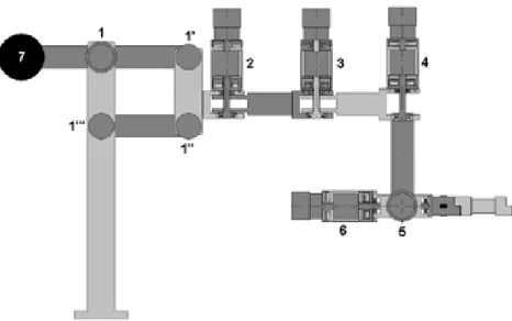
The robotic system used to perform needle biopsy, is the Navi-Robot developed by the Department of Mechanical Engineering at University of Calabria in cooperation with one of its spin off: Calabrian High Tech s.r.l. [31]. Originally designed for orthopedic applications, the Navi-Robot is a 6-DOF self-balancing arm. The kinematic structure is hybrid parallel/serial with rotational transducers to measure the relative angle between consecutive linkages. A schematic representation of the actual system is shown in Fig. 11.
Figure 11: Navi-Robot schematic representation
Each joint bears a clutch, a brake, an absolute encoder, and a motor-reducer group. Its kinematic chain is composed of a planar four-bar-linkage with horizontal axes, which provides a single vertical degree of freedom, while a 3-DOF structure mounting parallel vertical axes is linked to the rod of the four-bar- linkage mechanism. To the fourth rotational DOF a fifth hinge with axis perpendicular to the fourth is linked, being the sixth again perpendicular to the
2
the ionized rays absorption by both doctor and patient
when a biopsy is to be performed and the
improvement of the precision during these surgical
procedures.
2. The Navi-Robot
The Navi-Robot is a hybrid parallel/serial kinematic
structure with rotational transducers to measure the
relative angle between consecutive linkages. A
schematic representation of the actual system is
shown in Fig. 1.
Fig. 1. Structural Scheme of Navi-Robot
It consists in a planar four-bar-linkage with
horizontal axes at the beginning of the kinematic
chain, which gives a single vertical degree of
freedom, while a 3-DOF structure having parallel
vertical axes is attached to the rod of the
four-bar-linkage. To the fourth rotational DOF a fifth hinge
with axis perpendicular to the fourth is linked, being
the sixth again perpendicular to the previous, while
the axes of the last three hinges meet in a single
point, which behaves as a spherical hinge. A
schematic view of the 6-DOF arm’s structure, with
the identification of the base frame {B} and the end
effector frame {E} is shown in Fig. 2 in its
zero-reference configuration. A kinematic model
according to the International Standard ISO 9283 is
formulated, which relates the joints’ angles to the
end-effector pose in the base frame.
Fig. 2. Kinematic Scheme of Navi-Robot
For the transformation between the frame {0} on the
four-bar-linkage end the frame {1} the following
Transformation matrix can be calculated:
For the serial part of the robot the following D-H
parameters have been estimated:
Tab. 1. D-H table for the serial part of Navi-Robot
Transformation
id
i ia
i2
q
20
a
20
3
q
30
a
30
4
q
4d
40
/2
5
q
50
0
/2
e
q
6d
e0
0
The workspace of each arm has been evaluated to
be an approximate box of sizes 400x400x400 mm
3Kinematic performance of the system in terms of
the theoretical resolution is evaluated when 16bit
encoders are used as revolute joint sensors.
Resolution, which is defined according to the already
quoted International Standard ISO 9283, as the
smallest incremental movement of which the robot
end effector is capable of sensing, is a theoretical
characteristic and may be evaluated given the
configuration and the nominal dimensions of the
linkage. It is affected by the individual encoders’
resolution and depends on the instantaneous arm
configuration. An approximate relation provides an
estimate of the arm’s resolution as follows:
.
1 N i i iRS
d
q
q
(1)
where d
iis the distance between the end effector
endpoint and the revolute axis of the i
thjoint and it
depends on the arm configuration, i.e. on the vector
of joints’ angles
1
, , , , ,
2 3 4 5 6T
q q q q q q
q
(2)
while q
iis the i
thtransducer resolution. Since the
endpoint displacement, resulting from the smallest
incremental motion of the joints, varies significantly
throughout the workspace, Eq. (1) is practically used
for some particular system’s configuration where di
may be easily evaluated, e.g. in the zero-reference
configuration. In such a reference configuration, as
shown in Fig. 2, Eq. (1) gives an estimate of the
theoretical maximum resolution for the end effector
28
previous, while the axes of the last three hinges meet in a single point, which behaves as a spherical hinge. A schematic view of the 6-DOF arm’s structure, with the identification of the base frame {B} and the end effector frame {E} is shown in Fig. 12 in its zero- reference configuration. A kinematic model is formulated, which relates the joints’ angles to the end-effector pose in the base frame. The scheme below shows the “zero configuration” for the robot where each encoder is set to 0 while in the following table nominal parameters of the robot are reported.
Figure 12: Navi-Robot kinemtic model
Capitolo 1
Pagina 21
tre giunti G4, G5 e G6 in modo tale da consentire al tool gli stessi movimenti consentiti da una cerniera sferica (polso sferico). Una visione schematica della struttura del braccio centrale a 6 gradi di libertà, con i sistemi di riferimento col-locati in base alla Denavit-Hartenberg (D-H) è illustrata nella Figura 1.8, nella sua configurazione di riferimento.
29
Table 1: Navi-Robot geometric parameters
Geometry Value Unit Geometry Value Unit
d0 670 mm a2 470 mm a0 60 mm a3 470 mm L1 400 mm d4 250 mm L2 300 mm a6 70 mm L3 400 mm b6 0 mm L4 300 mm c6 60 mm a1 300 mm δ 3π /2 rad
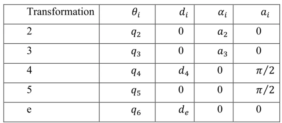
For the serial part of the robot the following D-H parameters were estimated:
Table 2: Navi-Robot D-H parameters
Transformation 𝜃! 𝑑! 𝛼! 𝑎! 2 𝑞! 0 𝑎! 0 3 𝑞! 0 𝑎! 0 4 𝑞! 𝑑! 0 𝜋 2 5 𝑞! 0 0 𝜋 2 e 𝑞! 𝑑! 0 0
The workspace of each arm has been evaluated to be an approximate box of sizes 400x400x400 mm3. Kinematic performance of the system in terms of the theoretical resolution is evaluated when 16 bit encoders are used as revolute joint sensors. Resolution, which is defined according to the already quoted International Standard ISO 9283, as the smallest incremental movement of
30
which the robot end effector is capable of sensing, is a theoretical characteristic and may be evaluated given the configuration and the nominal dimensions of the linkage. It is affected by the individual encoders’ resolution and depends on the instantaneous arm configuration. An approximate relation provides an estimate of the arm’s resolution as follows:
𝐑𝐒 ≈ 𝐝𝐢 𝐪 ∙ 𝛅𝐪𝐢 𝐍
𝐢!𝟏
𝐑𝐒 ≈ 𝐍𝐢!𝟏𝐝𝐢 𝐪 ∙ 𝛅𝐪𝐢
[1]
where di is the distance between the end effector endpoint and the revolute axis
of the ith joint and it depends on the arm configuration, i.e. on the vector of joints’ angles q = [q1 , q2 , q3 , q4 , q5 , q6 ]T while δqi is the ith transducer
resolution. Since the endpoint displacement, resulting from the smallest incremental motion of the joints, varies significantly throughout the workspace, equation 1 is practically used for some particular system’s configuration where may be easily evaluated, e.g. in the zero-reference configuration. In such a reference configuration, as shown in Fig. 12 equation 1 gives an estimate of the theoretical maximum resolution for the end effector endpoint. Hence, when adopting 16 bit encoders’ with a resolution of about 0.0055 degrees per step, equation 1 gives a maximum value for the resolution of 0,3 mm.
2.1 Direct Kinematic
As for the kinematic model, the transformation between frame {B} on the four-bar-linkage end frame {1} we can consider the following scheme
31
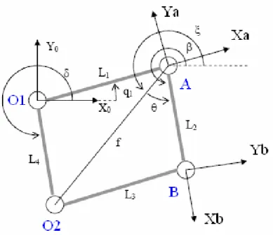
Figure 13: four bar linkages scheme
Due to geometric and assembly errors, the lengths of the bars: L1, L2,L3, L4,
could not be exactly equal to the nominal values, as well as the fixed hinges O1, O2 could not be exactly located at the nominal positions. These errors can
lead to a rotation, not desired in the original design, of the bar L2 with respect
the horizontal (dotted line in Fig. 13) and represented by the angle β. This angle depends on: the lengths of the bars, the angle δ, and on the joint’s angle q1. The relationship between the angle β and q1 can be calculated applying the
sum of vectors on the triangle O1, A, O2. For the four bar linkages, in the table
below the nominal parameters with the error parameters associated are reported. Nominal Parameter Error Parameter Associated q1 δk5 L1 δk6
Capitolo 4 - Modello Cinematico del Navi-Robot
75
utilizzando la convenzione modificata di DH per descrivere le
trasformazioni tra giunti consecutivi aventi assi paralleli.
4.3.1 Cinematica del quadrilatero
Si prenda in considerazione una configurazione generica del
quadrilatero articolato, in modo da inglobare tutte le sue possibili
distorsioni dalla struttura di progetto (figura 4.5).
Figura 4.5
E’ ovvio che errori geometrici sulle aste del sistema piano (L
1,
L
2, L
3, L
4) e sul posizionamento delle due cerniere fisse ( ),
possono provocare errori che portano alla nascita di un certo
angolo dell’asta L
2rispetto all’orizzontale non desiderato nella
fase di progetto. Tale angolo è funzione delle lunghezze delle
aste, dell’angolo e del parametro q
1, angolo del movente. La
relazione fra e q
1si può trovare tramite il metodo della chiusura
32 L2 δk7 L3 δk8 L4 δk9 δ δk10
Hence calling f the vector between the hinges O2 and A, we can state the
following relations:
𝑓 = ((𝐿… ((𝐿!+ 𝛿𝑘!) sin 𝛿 + 𝛿𝑘!" − (𝐿!+ 𝛿𝑘!) sin 𝑞!+ 𝛿𝑘! )!+ ⋯
!+ 𝛿𝑘!) cos 𝛿 + 𝛿𝑘!" − (𝐿!+ 𝛿𝑘!) cos 𝑞!+ 𝛿𝑘! )! [2]
𝜉 = arctan ((𝐿!+ 𝛿𝑘!) sin 𝛿 + 𝛿𝑘!" − (𝐿! + 𝛿𝑘!) sin 𝑞!+ 𝛿𝑘! )! ((𝐿!+ 𝛿𝑘!) cos 𝛿 + 𝛿𝑘!" − (𝐿! + 𝛿𝑘!) cos 𝑞!+ 𝛿𝑘! )! [3]
𝜃 = ±arcos −(𝐿!+ 𝛿𝑘!)!+ 𝑓!+ (𝐿!+ 𝛿𝑘!)!
2𝑓(𝐿!+ 𝛿𝑘!) [4]
𝛽 = 𝜉 + 𝜃 [5]
We can now state the equations which describe the direct kinematic of the robot or rather which can allow to define the pose (translation and rotation) of the end-effector with respect the base robot coordinate system.
33
T0A = Rz(q1+ δk5)* Dx(L1+ δk6) DH plane [7] TAB = Rz(β - q1 - δk5)* Dx(L2+ δk7) DH plane [8] TB1 = Rz(π/2 + δk11)*Dz(δk12)*Dx(a1 + δk13)*Rx(-π/2 + δk14) DH [9] T12 = Rz(q2+ δk15)*Dx(a2+ δk16)*Rx( δk17)*Ry( δk18) DH mod [10] T23 = Rz(q3+ δk19)*Dx(a3+ δk20)*Rx( δk21)*Ry( δk22) DH mod [11] T34 = Rz(q4+ δk23)*Dz(-d4 + δk24)*Dx( δk25)*Rx(π/2 + δk26) DH [12] T45 = Rz(q5- π/2+ δk27)*Dz( δk28)*Dx(δk29)*Rx(-π/2 + δk30) DH [13]
T5t = Rz(q6)*Dz(c6+δk31)*Dy(b6+δk32)*Ry(5/4*π+δk33)*Dz(-a6+
+δk34)*Rx(δk35)*Rz(δk36) [14]
where:
Ri elementary rotation about the axis i
Di translation along the axis i
δKi error for i-parameter
For the transformations: TB0 , T0A , TAB , TB1 , T34 , T45 , T5t the Denavit-Harteberg notation was used where:
Ti-1, i = Rz(θi) * Dz(di) * Dx(ai) * Rx(αi) [15]
As for the transformation T12 , T23the modified Denavit-Harteberg notation was used, where:
Ti-1,i= Rz(θ)*Dx(r)*Rx(α)*Ry(β) [16]
34
TBt = Tw0* T0A* TAB* TB1* T12* T23* T34* T45* T5t [17]
2.2 Joint’s Architecture
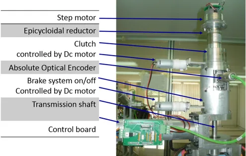
As mentioned before and as it can be seen in the figure below (Fig. 14), each joint of the robot comprises, starting from the top to the bottom, the following components: a motor-reducer, a step motor, a first braking system, an absolute encoder, and a second braking system identical to the previous one. The joint’s frame is connected to a shaft, supported by two bearings, whose axis is orthogonal to link’s axis on which all the components are connected to. The braking system placed above works as a clutch and allows coupling or decoupling the step motor to the joint’s axes. The second braking system instead, is directly connected to the shaft and works as simple brake.
Figure 14: Joint’s architecture
The braking system plays an important role in the Navi-Robot architecture, since accordingly to the idea of the designers this robot must be able to turn itself into a measurement system and vice versa. This particular feature makes
35
the Navi-Robot different from other surgical robot or image-guided robotic devices allowing a wide range of operations and at the same time provides surgeons great flexibility and freedom of choice. The aim of the designers in fact is not replacing the surgeon, but to assist him in placing/guiding instruments and planning interventions. In order to achieve this goal the braking system should work mainly as a mechanical switch in static conditions, since it must keep the joints in a desired position. The brake also should provide high brake torque, low energy consumption and low amount of space. At the state of the art none of the commercial devices meet these requirements, thus a new concept brake was designed.
2.3 End-Effectors
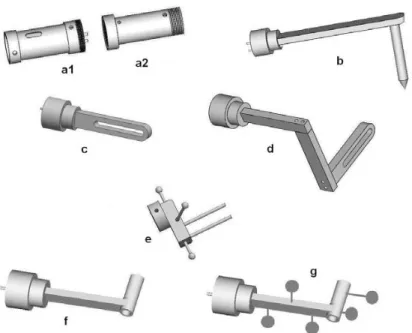
Since the Navi-Robot was designed to perform several different surgery procedures, such us: laparoscopic, orthopedic, oncologic etc., several different end-effectors can be used (Fig 15) often, more than one is required for the same medical procedure. Thus, a system allowing exchanging the tool, without re-calibrating and re-programming every time the robot could be very helpful. That being so, a first hardware solution, which was designed during this project but not manufactured yet, is providing the system with an intermediate stage (frame a2), which can be sterilized as well, so that the end-effector can be replaced during a surgery without risk of contamination. Thus, both the intermediate end-effector and all the various end-effectors must be purely mechanical components, while the unsterile part of the end effector (a1), which belong to the last link of the robot, must be able to recognize which end-effector is installed.
36
Figure 15: CAD models of some of the end effectors for orthopedic procedures, being b the pointer, c and d the sawing guide, e the bone clamp, and f and g the drilling guides
In this project, the end-effector used to hold the needle during the positioning and insertion procedure, (type g in Fig. 15) was simply locked into the shaft of link 6° as well as has been done for the end-effector used for the calibration procedure that will be discussed in section 2.8.
Figure 16: End-effector needle holders
As can be seen in Fig. 16 the end-effector is made of four parts: (1) a flat frame SCIENTIFIC JOURNAL OF IFToMM “PROBLEMS OF MECHANICS” ! 4(41), 2010
5. END EFFECTOR
Since many are the possible end effectors to be used (figure 11), a way to univocally inform the system of the end effector actually used was devised. In fact let’s first notice that the end effectors should be interchangeable during surgery, and that each end effector must be sterile. For this reason the idea to provide the system with a sterilizable intermediate end effector (a2) came as natural, so that the end effector can be changed during a surgery without risk of contamination. Thus both the intermediate end effector and all the various end effectors must be purely mechanical components, while the unsterile part of the end effector (a1), that is to say the base of the 7th link, must be able to read which end effector is installed.
Fig. 11. CAD models of some of the end effectors for orthopaedic procedures, being b the pointer, c and d the sawing guide, e the bone clamp, and f and g the drilling guides
Moreover it may be useful, particularly in the case of orthopaedic applications, to know the value of the force exerted on the end effector by the doctor during the surgery. For this purpose strain gauges will be placed on the 7th link base (a1), together with four sets of photodiodes and phototransistors to read the position of four
bars, that are positioned in the intermediate end effector, pushed out of it toward the final end effector, but with corresponding holes on the opposite side, so that bars can be pushed back. The final end effector (b-g) may present flat surfaces or holes in correspondence to the four bars of the intermediate end effector, so as to push back or let in the bars, while the photo sets read the bar position, determining which end effector in installed, enabling recognition of fifteen different end effectors.
6. ELECTRONIC CONTROL
The electronic control system is designed as a master-multi slaves chain of microprocessors. Each arm of the robot is equipped with a six microcontroller, one per joint, working as a slave, plus one, that works as a master for the chain. The master of the chain is used also to interface the robot with the computer, using USB2 connection. The connection between microprocessor is serial (bus I2C) and a series of buffers are used in order to increase the communication speed. The bus frequency is 400 KHz. This bus frequency allows communicating with all slaves, using a 4 byte frames format, in 1.6ms. Presently the user controls the equipment with an application in Matlab for Windows, through ad hoc routines written in C++, which makes the system extremely simple to work with for an engineer. Naturally, the outcome will be writing final programs in C++ for Linux.
37
bearing spherical markers (3), the alignment cylinder (2) and a cap (4) which allows the surgeon to adjust the friction by which the needle is held in position. In particular, the lower section of the cap (Fig. 16) is locked in alignment cylinder, and it hosts a seal, which can be compressed by three screws positioned at 120° with respect to each other. Tightening the screws increases the friction, allowing the surgeon to block the needle at a defined depth into the cylinder, while, untightening the screws allows changing the needle or guiding it during insertion.
Figure 17: Needle’s cap for friction adjustment
2.4 Electronic Control
Electronic control system is designed as a master-multi slaves chain of microprocessors. The robot arm is equipped with six microcontrollers, one per joint, working as a slave, plus one that works as a master for the chain. The master of the chain is used also to interface the robot with the computer, using USB2 connection. The connection between microprocessor is serial (bus I2C) and a series of buffers are used in order to increase the communication speed. The bus frequency is 400 KHz. This bus frequency allows communicating with all slaves, using a 4 byte frames format, in 1.6ms. Currently, the user controls the equipment with an application developed in Matlab for Windows, through ad hoc routines written in C++, which makes the system extremely simple to work with. The current software can require from each joint controller the
38
actual value of the encoder’s angle (all values are recorded at the same time using a general call). It also can open or lock one the brakes, or it can require reaching the specified angle from the current value, in a given time, starting from a second general command that starts the motion of all joints. Each controller then calculates its ramps of acceleration and deceleration.
2.5 Braking System Design
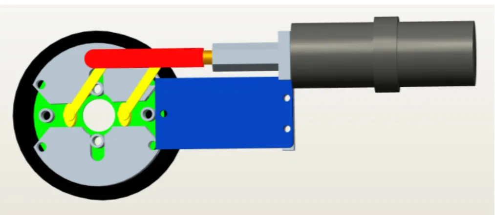
The brake system prototype developed for the robotic system, as shown in the CAD model below, is a drum brake working as a switch on/off and whose brake shoes are placed in contact with the housing by the rotation of two cams.
Figure 18: brake system unlocked position
Figure 19: brake system locked position
39
housing of the brake is rigidly linked. Pulling the slider, the cams rotate, opening the brake shoes outwards. In this configuration (“locked position” Fig. 19) brake shoes and housing come in contact each other and the friction avoid the relative motion between the housing, hence the shaft as well, and the frame. When the slider is pushed inside, the brake shoes helped by two springs (shown in Fig. 20) come back in the previous configuration (“unlocked position” Fig. 18) unlocking the shaft. The cams are guided by two supports belonging to the frame, allowing linking a cover, which keeps all the components in place. The slider instead, is linked to a sleeve rigidly attached to a shaft of a motor-reducer, which control the locking mechanism of the brake whose actual picture can be seen below.
Figure 20: Brake system assembly prototype
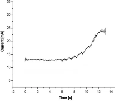
The control strategy adopted for activating/deactivating the braking devices is based on the measure of the current absorbed by the electric actuator, i.e. the revolute motor. Calibrating the device, the maximum current absorbed by the motors to brake/release each joint is registered. A lower value, higher than the value registered during the activating phase, is hence used as a threshold in the control algorithm, which stops the input power supply when the current overtakes this limit. As an indication, Fig 21 shows a graph of the current absorbed by the motor (DC Johnson 3F2212), when braking, as a function of
![Figure 7: Needle-guide by Radeka [22]](https://thumb-eu.123doks.com/thumbv2/123dokorg/2876181.9874/22.892.201.716.151.364/figure-needle-guide-by-radeka.webp)
![Figure 9: ROBOPSY™ system [24]](https://thumb-eu.123doks.com/thumbv2/123dokorg/2876181.9874/23.892.258.694.698.977/figure-robopsy-system.webp)