a.a. 2008/2011
Università degli Studi di Catania
Scuola Superiore di Catania
International PhD
in
Energy
XXIV cycle
Fault Tolerant Sensorless
Permanent Magnet Synchronous
Motor Drives
Alberto Gaeta
PhD Coordinator
Tutor
2
Abstract
High cost and complexity of fault tolerant motor drives has relegated them to
mission critical, no-compromise applications.
Heeding to this target application, past research efforts have been mainly focused
on developing highly redundant, multiphase fault-tolerant solutions able to assure a
very high fault tolerance level.
However, many other applications would benefit from the availability of solutions
ensuring an acceptable level of fault tolerance.
The present work shows that, if tolerance is limited to few common faults and a
reasonable performance penalty after a fault is accepted, a three-phase, voltage
source inverter-fed, sensorless motor drive can be made fault tolerant by acting
mainly on the control strategy, thus keeping to a minimum the required hardware
modifications and additions.
After an initial classification of the possible faults which may affect three-phase
VSI-fed drives, a fault detection and identification technique for converter faults is
analyzed, able to ensure reduced response times. Therefore, modifications to a
sensorless rotor position estimation technique are proposed in order to make a
sensorless drive as fault tolerant as their sensored counterparts. Succesively,
considering a PMSM motor with star center accessibility, two-phase sensorless
operation is extensively studied and a new model is introduced maintaining the
same control performance of a standard qd reference frame model. The new model
is used for vector control of the machine either in sensored and sensorless
conditions to confirm that advanced control of two-phase sensorless operation is
the only post-fault strategy allowing the elimination of any redundant hardware.
3
Abstract...2
Contents...3
1. INTRODUCTION...7
1.1 Background...7
1.2 References...8
PART I...9
2. FAULT CLASSIFICATION IN VOLTAGE SOURCE INVERTER FED MOTOR...
DRIVES...10
2.1 Fault Classification...10
2.2 Voltage Source Inverter Faults...12
2.3 Machine Winding Faults...17
2.4 Power Mains Cable Faults...19
2.5 Motor Cable Faults...20
2.6 Current Sensor Faults...21
2.7 Mechanical Sensor Faults...22
2.8 Remedial strategies...23
2.9 References...24
3. FAULT TOLERANT MOTOR DRIVE TOPOLOGIES...27
3.1
Literature review...27
3.2 Proposed innovative fault isolation scheme...32
4
4.1
The importance of fast fault detection and identification in...
sensorless motor drives...41
4.2 Fault detection technique description...42
4.3 Fault identification technique description...45
4.4 Leg current reconstruction...48
4.5 Simulation results...50
4.6 References...52
PART II...54
5. EFFECTS OF FAULTS AND LINE DISTURBANCES ON ROTOR POSITION....
ESTIMATION...55
5.1 Introduction...55
5.2 HF Injection-based technique description...56
5.3 Model-based technique description...58
5.4 Experimental results...59
5.5 References...63
6. OPEN-PHASE FAULT TOLERANT SENSORLESS TECHNIQUE FOR...
STANDARD TOPOLOGY INTERIOR PERMANENT MAGNET MOTOR...
DRIVES...64
6.1
Description of the proposed technique...64
6.2 Experimental results...67
5
TECHNIQUES BASED ON CARRIER SIGNAL INJECTION...73
7.1 Interaction of transient components with rotor position estimation...73
7.2 Mechanical model-based estimator...80
7.3 Experimental results...83
7.4 References...88
8. MODELING OF THREE-PHASE PERMANENT MAGNET SYNCHRONOUS...
MOTORS FOR BALANCED AND OPEN-PHASE OPERATION...89
8.1
Introduction...89
8.2
Mathematical model in phase coordinates for balanced operation...90
8.3 Mathematical model in stationary qd0 coordinates for balanced...
operation...93
8.4 Mathematical model in rotor qd0 coordinates for balanced operation...94
8.5 Mathematical model in phase coordinates for open-phase operation...97
8.6 Unbalanced mathematical model in stationary q
ud
ucoordinates for...
open-phase operation...98
8.7 Mathematical model in rotor qd coordinates for open-phase...
operation...102
8.8 References...105
9. OPEN-PHASE VECTOR CONTROL OF THREE-PHASE PERMANENT...
MAGNET SYNCHRONOUS MOTOR DRIVES...106
9.1 Balanced mathematical model in rotor qd coordinates for open-phase...
operation...106
6
9.4 Current profiling techniques...113
9.5 Third order current harmonic compensation...119
9.6 Experimental results...120
9.7 References...126
10. SENSORLESS ESTIMATION IN THREE-PHASE PMSM DRIVES UNDER...
OPEN-PHASE OPERATION...127
10.1
Introduction...127
10.2 Balanced mathematical model in stationary qd
coordinates for...
open-phase operation...127
10.3 Modifications to SC2 sensorless technique for open-phase operation..130
10.4 Effects of disturbance terms on HF injection-based SC1 technique...132
10.4 Experimental results...135
INTRODUCTION
7
1.1. Background
Although rapidly increased in the last years, the number of installed fault-tolerant electrical drives is only a minor fraction of the total number of installed drives.
An obstacle to a wide diffusion of fault-tolerant electrical drives is their higher cost and complexity compared to traditional solutions which relegate them to mission critical applications where hydraulic systems and combustion engines were extensively used in the past.
Typical examples are automotive applications [1][2], aerospace applications [3] ÷ [5], marine applications [6][7], nuclear power and chemical plants applications, military applications.
Most of the above listed applications require an high level of fault tolerance: almost all types of fault must be tolerated and very good if not rated performance must be guaranteed after a fault. It is important to emphasize that such requirements can be satisfied only by the existence of multiple redundancies, at the hardware and control levels. As an example, the use of motors with thermally and electrically isolated multiple phases fed by independent converters is the most common choice in case of critical applications which demand for drives highly tolerant to converter or motor faults.
Due to the high level of hardware redundancy introduced by the multiple phases approach, drive operation is not compromised by a fault: the choice of the particular post-fault strategy to be used and the amount of additional hardware to be included into the drive depend only on the desired level of post-fault performance.
Obviously the more are the system redundancies, the greater are the efforts and costs needed to design and build a fault-tolerant drive.
However, many civil, commercial, and industrial applications would benefit from the availability of low cost fault tolerant drives even if they would be able to guarantee tolerance only to few common faults and limited performance after a fault: a reduction of the overall complexity and production cost is the only way to spread the diffusion of fault-tolerant drives.
For this reason, a three-phase motor supplied by a Voltage Source Inverter (VSI) has been chosen as starting point for all the considerations, analyses and results which will be presented in this work.
Moreover, most of the research efforts in the past have been spent on the development of fault-tolerant solutions suitable for vector controlled drives equipped with mechanical sensors.
Sensorless rotor position estimation techniques for three-phase fault-tolerant drives have been taken into consideration mainly when dealing with mechanical sensor failures, as a way of obtaining a sensor redundancy at the control level, useful for fault recognition and post-fault operation.
8 On the contrary, in the present work, fault tolerant solutions will be designed for full sensorless operation of the drive, thus allowing the elimination of the mechanical sensors and further reducing costs.
However, switching to sensorless techniques opens new challenging problems: are sensorless techniques robust to faults? If not, is it possible to make modifications in order to maintain a sensorless operation even after a fault?
The present work will try to reply those questions.
1.2. References
[1]. M. T. Abolhassani, H. A Toliyat, "Fault Tolerant Permanent Magnet Motor Drives for Electric Vehicles", IEEE International Electric Machines and Drives Conference - IEMDC, pp. 1146 - 1152, May 2009
[2]. A. Benedetti, N. Bianchi, S. Bolognani, M. Dai Pre, P. Molari, P. Morelli, M. Tomasini, L. Tubiana, M. Zigliotto, "PM Motor Drives for Steer-by-Wire Applications", 40th Industry Applications Conference - IAS, Vol. 4, pp. 2857 - 2864, October 2005
[3]. A. Boglietti, A. Cavagnino, A. Tenconi, S. Vaschetto, "The safety critical electric machines and drives in the more electric aircraft: A survey", 35th Annual Conference of IEEE Industrial Electronics - IECON, pp. 2587 - 2594, November 2009
[4]. G. J Atkinson, B. C. Mecrow, A. G. Jack, D. J. Atkinson, P. Sangha, M. Benarous, "The design of fault tolerant machines for aerospace applications", IEEE International Conference on Electric Machines and Drives, pp. 1863 - 1869, May 2005
[5]. J. W. Bennett, A. G. Jack, B. C. Mecrow, D. J. Atkinson, C. Sewell, and G. Mason, "Fault-tolerant control architecture for an electrical actuator", 35th Annual IEEE Power Electronics Specialists Conference - PESC, Vol. 6, pp. 4371 – 4377, June 2004
[6]. S. Kanerva, J. F. Hansen, "State of the Art in Electric Propulsion - Viewpoint On Redundancy", IEEE Electric Ship Technologies Symposium - ESTS, pp. 499 - 504, April 2009
[7]. S. Siala, E. Guette, and J. L. Pouliquen, "Multi-inverter PWM control: A new generation drives for cruise ship electric propulsion", 10th European Conference on Power Electronics and Applications - EPE, September 2003
9
FAULT CLASSIFICATION IN VOLTAGE SOURCE
INVERTER FED MOTOR DRIVES
10
2.1. Fault Classification
In first instance, VSI drive faults can be divided in faults affecting the control part of the drive; faults affecting the power part of the drive; faults affecting the mechanical part of the drive. Faults affecting the mechanical part of the drive and the digital control unit will not be included in the following classification: only faults affecting inverter, motor windings, interconnection cables and sensors will be considered.
Figs. 2.1 and 2.2 show localization, origin and severity of several faults which may affect a VSI drive.
VSI DRIVE FAULTS
MACHINE CABLE SENSOR INVERTER
Severity: Low
Severity: Fatal DC link capacitor short
circuit fault (F4) Severity: Fatal Earth fault on
DC bus (F3) Rectifier diode short
circuit fault (F1)
Rectifier diode open circuit fault (F2)
Single switch or freewheeling diode short
circuit fault (F8)
Single gate driver open circuit fault
(F9)
Multiple gate driver open circuit fault
(F9 on all legs) Severity: Fatal
Severity: Low to Fatal
Severity: Very High to Fatal
Single gate driver short circuit fault
(F10) Severity: High to Fatal
DC link capacitor open circuit fault (F5)
Severity: Medium
Single switch open circuit fault
(F6)
Severity: High Severity: High to Fatal
Single freewheeling diode open circuit fault
(F7)
Severity: Very High to Fatal
Fig. 2.1. VSI Drive faults localization, origin and severity classification - Part 1.
VSI DRIVE FAULTS
MACHINE CABLE SENSOR INVERTER
Turn to turn short circuit fault (F11)
Phase to phase short circuit fault (F12)
Severity: Fatal
Phase to frame short circuit fault (F13)
Severity: Fatal
Severity: Very High to Fatal AC
LINECABLEFAULTS
Severity: Fatal
MOTORCABLEFAULTS
Line to ground short circuit fault (F15)
Single phase line cable disconnected (F16)
Line to line short circuit fault (F17)
Severity: Low
Severity: Fatal Line to ground short circuit fault (F18)
Line to line short circuit fault (F19)
Severity: Fatal Severity: Fatal
CURRENT SENSOR FAULTS
Severity: Low to Fatal
Severity: Fatal
MECHANICAL SENSOR FAULTS
Current sensor offset + gain errors
Current sensor breakdown
Severity: Fatal Open phase fault (F14)
Severity: High to Fatal
Single phase line cable disconnected (F14) Severity: High to Fatal
Mechanical sensor breakdown Severity: Medium to Fatal
Mechanical sensor slippage
Severity: Medium to Fatal Mechanical sensor intermittent operation Severity: Fatal
Current sensor intermittent operation
11 A schematic diagram of a standard VSI drive, suitable for vector control of a motor, is depicted in Fig. 2.3.
AC Source
Rectifier DC Link Inverter
Motor F4 F1 F2 Gate Driver Gate Driver F9 F8 F18 F19 F14 F3 Va Vb Vc Fuses F16 F15 F1 7 F11 F12 F13 Vcc_leg GND_leg Vcc GND F10
Current Sensor Current Sensor Current Sensor Voltage Sensor
F3
F5
F10
F6 F7
Fig. 2.3. Schematic view of a VSI drive with some possible faults highlighted in red.
Considering that most of the faults listed in Figs. 2.1 and 2.2 are equivalent to the presence of a short-circuit or an open-circuit connection, the occurrence of such faults is represented in Fig. 2.3 as the closing or opening of several switches.
The possibility of multiple different faults occurring at the same instant is very rare and so it is not considered in this study; however the possibility of multiple faults occurring as a consequence of the escalation of an undetected fault is taken into consideration.
For the following analysis, it is assumed that the same control strategy, used during healthy operation of the drive, is maintained even after a fault, as usually happens in case of a non fault-tolerant drive.
12
2.2. Voltage Source Inverter Faults
A survey by Tavner et al [2] on the reliability of power electronics converters for industrial applications shows that 31% of all converter failures are in the power devices, 18% in the capacitors, 14% in the gate driver circuitry and 5% in the inductors.
It should be noted that percentages of capacitor and inductor failures are lower in VSI drives, where passive energy storage elements are charged at lower frequencies compared to those usually used in switching converters, also considered by the survey.
Another survey performed on multi-megawatt Variable Speed Drives (VSDs)[3] details the reliability of each part of the drive in FIT (number of failures for a working time of 109 hours), showing the high incidence of power devices and gate drivers failures.
Rectifier diode short circuit fault (F1)
Description: a diode is not capable of stopping current conduction, remaining in a short-circuit state indefinitely.
Causes: This fault can be caused by aging of the rectifier diodes or an excessive inrush current as a result of disturbances coming from power mains or a failure of the inrush current limiter during inverter power on.
Consequences: This fault will cause excessive current stresses on the power line fuses. If the fuse of the faulty diode blows first, the diode bridge rectifier will continue operating in single-phase mode, generating higher amplitude, lower frequency DC Bus voltage ripple and consequently torque and speed ripple on the machine; otherwise a fuse of a healthy phase and the fuse of the faulty phase will blow, causing a total interruption of power to the inverter. Moreover, in case of single-phase operation of the rectifier bridge, the remaining diodes will carry 50% more average current compared to the three-phase operation[1].
Severity: Low to Fatal, depending on the sequence in which the fuses blow.
Rectifier diode open circuit (F2)
Description: a diode is not capable of conducting current, remaining in an open-circuit state indefinitely.
Causes: This fault can be caused by bonding wires, solder joints, printed circuit board or packaging failures as a result of overcurrent, thermal cycling, harsh environment conditions, vibrations.
Consequences: The rectifier bridge will operate in single-phase mode, with consequences already described for fault F1.
13
Earth fault on DC bus (F3)
Description: The lower or upper rail of the DC Bus capacitor is connected to earth.
Causes: This fault can be caused by breakdown of insulation between DC bus rails and inverter chassis.
Consequences: After the fault, power mains will be connected to earth through the upper or lower rectifier diodes, depending on which DC bus rail is affected by the fault. High currents will start to flow toward earth causing a total power disruption as a result of the intervention of differential earth leakage protections.
Severity: Fatal
DC Link capacitor short circuit fault (F4)
Description: DC bus capacitor is short circuited.
Causes: This fault can be caused by insulation breakdown of oxide film or electrolytic paper as a result of aging, production defects (metal particles adhering, burrs on electrode foils or leads, defective oxide film, improperly leads connection) or improper use or mounting (excessive stress applied to leads, excessive ripple current, over voltage impressed, reverse voltage applied, severe charging-discharging, excessive working temperature, excessive soldering heating, vibrations)[4].
Consequences: After the fault, the DC bus capacitor will be discharged suddenly. High power mains line currents will start to flow causing the blowing of two fuses and so a total disruption of power to the inverter.
Severity: Fatal
DC Link capacitor open circuit fault (F5)
Description: DC bus capacitor is open circuited.
Causes: This fault can be caused by aging, defective or failed leads connection originated at time of production or as a result of mechanical stresses and vibrations during mounting and/or use; leads or electrode foils corrosion as a consequence of contamination with halogenated ions present at production time or contained in cleaners, coatings and adhesives used during mounting [4].
Consequences: After the fault, the DC bus capacitor is disconnected from one or both DC bus rails. The inverter is able to continue operating even if without any reservoir of energy [5].
Current to the motor is supplied directly by power mains, with all the problems associated with the very high DC bus voltage ripple and higher DC bus source impedance due to power mains cables inductance and resistance.
14
Single switch open circuit fault (F6)
Description: a power switch is open-circuited.
Causes: This fault can be caused by a problem in the gate driver circuitry as described later, by bond wire lifting [6] or solder joints fatigue [7] due to thermal cycling, by bond wire lifting or package rupture due to over-current [8], by mechanical stresses, vibrations.
Consequences: Assuming a F6 fault as represented in Fig. 2.3 and a negative current (ingoing the affected leg), leg output can be connected to the upper or lower DC rail just opening or closing the lower power switch respectively.
On the contrary, as soon as the current in the affected leg tries to reverse direction in order to become positive, the affected leg output cannot be anymore connected to the upper DC rail, avoiding the completion of current direction reversal.
Considering that phase inductances cannot sustain any dc voltage at steady state, the negative dc offset, appearing at the affected leg output as a consequence of a F6 fault, must be sustained by the phase resistance: a dc offset, with the same sign of the dc voltage offset, appears in the affected leg current [1].
Obviously, due to the wye connection of motor windings, a dc current also appears on the other phases, generating unequal stress in the remaining healthy power switches: these effects may cause secondary faults in the inverter power switches or motor windings.
After the fault and at steady state, the motor operates alternatively in three-phase mode (when current in the affected leg is negative) and in open/single phase mode (when current in the affected leg is zero and supposing the star center is inaccessible): motor MMF is alternatively rotating and pulsating. This working condition causes high torque and speed ripples and, depending on the load inertia and torque characteristics and on speed conditions at the time of the fault, the drive may be or not be able to continue operating. Similar considerations apply in case of a fault to a lower switch.
Severity: High.
Single freewheeling diode open circuit fault (F7)
Description: a freewheeling diode is open-circuited.
Causes: This fault can be caused by bond wire lifting [6] or solder joints fatigue [7] due to thermal cycling, by bond wire lifting or package rupture due to over-current [8], by mechanical stresses, vibrations.
Consequences: in case of a F7 fault as represented in Fig. 2.3, the lower switch of the affected leg will fail during turn-off when attempting to stop a negative current flowing in the affected motor phase. In fact, the overvoltage caused at turn-off by the inductive current interruption cannot be anymore clamped to the upper DC bus rail due to the fault in the freewheeling diode. The lower power switch will experience a voltage breakdown due to avalanche [9].
15 Moreover the high dv/dt generated at turn-off may cause a latch-up failure [10] of the upper power device, leading to a fatal DC bus short circuit if protection fuses are missing.
Even if the fault occurs during the half-period when the affected leg current is positive and the faulted diode is not required for proper inverter operation, the failure of the lower switch is only delayed. In fact, when the affected leg current will try to reverse flowing direction, each turn-on of the lower switch will build up a negative current into the motor winding, while each turn-off will cause an overvoltage. The switch may fail even after many turn-on/turn-off cycles, depending on the current level reached at the end of each turn-on period which is linearly related to the turn-on time. Similar considerations apply to the case of a fault to a lower freewheeling diode.
Severity: Fatal.
Single switch or freewheeling diode short circuit fault (F8)
Description: a power switch or a freewheeling diode is short-circuited.
Causes: This fault can be caused by a short-circuit fault in the gate driver circuitry, as described later, or by a damaged power device. Excluding the case of faults related to design errors, the increase of thermal resistance between junction and case as a consequence of thermal cycling is the major reason for power switch short circuit faults. The increased internal working temperature, due to degradation of the die bond, may lead to a fault while the power switch is turned-on (Fault Under Load) [11] or at turn-off as a consequence of a latch-up of the parasitic thyristor [12].
Consequences: if the fault is not immediately detected, when the healthy power device on the same leg is turned on, a low resistance path is created between the DC Bus rails leading to a very high short circuit current. If fast fuses or gate drivers with de-saturation control [11] are not present for leg shoot-through protection, the healthy power switch will be destroyed and the DC bus will be suddenly discharged with consequences similar to a DC Link capacitor short circuit fault (F4).
Severity: Very high to fatal.
Single gate drive open circuit fault (F9)
Description: a gate driver output is inoperative or open-circuited.
Causes: This fault can be caused by a problem in the connection between gate driver and power switch, as a consequence of thermal cycling, mechanical stresses, vibrations or by a failure of an upper gate driver power supply.
Consequences: Considering the lack of any gate driving, the power switch may be activated by the companion power device commutations, causing a fatal leg shoot-through fault [13].
16
Single gate drive short circuit fault (F10)
Description: a gate driver output is fixed at the low or high voltage level.
Causes: This fault can be caused by a problem in the gate driver as a consequence of gate driver or power switch aging. In fact power switch input characteristics, as seen by the gate-source terminals, vary with temperature [12] and aging [14]. In particular input capacitance increase with aging [15], demanding for more severe gate driver current sinking/sourcing capability.
Consequences: The power switch connected to the faulted gate driver remains in an open-circuit or short-circuit state, depending on the particular fault considered.
Consequences of the fault are equivalent to a single power switch open-circuit fault (F7) or to a single power switch short-circuit fault (F8).
Severity: High to Fatal.
Multiple gate driver open circuit fault
Description: all gate drivers are inoperative.
Causes: Usually, for cost reasons, low-side gate drivers are powered by the same power supply (master) while high-side gate drivers are powered by isolated power supplies (slaves) derived from the master power supply. A failure in the master power supply is the main cause of a multiple gate driver open circuit fault.
Consequences: after the fault, all power switches are open-circuited and the inverter is seen by the motor as un uncontrolled three-phase rectifier, since only the freewheeling diodes are still active. Energy stored in the motor is recovered into the DC bus capacitor and, in this particular case, the motor is said to operate in uncontrolled generator mode (UCG) [16].
In order to avoid serious damages occurring to inverter and/or motor, they must be properly designed, for example including a regenerative or dissipative brake in order to limit DC bus over-voltage or acting on both the magnets flux and d-axis inductance in order to limit phase currents below the rated inverter/motor current.
Severity: Fatal
Single switch misfiring
Description: a power switch is turned off or on randomly.
Causes: This fault can be caused by intermittent failures on gate driver circuitry, in the logic circuitry or in the interconnections.
Consequences: depending on the type of intermittency, consequences can be similar to that of an open-circuit switch fault or to that of a short-circuit fault.
17
2.3. Machine Winding Faults
A survey by Thorsen and Dalva [17] on the reliability of induction motors shows that electrical faults to stator windings are the most common type of motor faults (15%), after bearing faults (51%).
It should be noted that the high percentage of bearing faults is related to the fact that most of the motor considered in the survey were operated full time with very rare maintenance.
Failure rates for three-phase drives [18] show that open-circuit faults are the most common type of stator winding failure, followed by short circuit type faults.
Turn-to-turn short circuit fault (F11)
Description: Two or more winding turns within a motor phase are short circuited due to insulation failure, leading to a shorted coil of two or more turns.
Causes: Overheating is one of the major causes of winding insulation breakdown: a common rule states that, for every 10 degrees of increase in windings temperature, the insulation life is reduced by half.
Overheating may be caused by overload, poor power condition, high effective service factor, frequent stops and starts and environmental reasons.
For example, a small unbalance in phase voltages may have a negative effect on windings temperature. Another common rule states that a voltage unbalance of 3.5% per phase may cause an increase by 25% of the temperature in the phase with the highest current.
Moreover modern VSDs may exhibit a greater incidence of motor faults, considering that the advantage of soft starting offered by inverters may be overcome in some applications by the negative effects like partial discharge and corona effect caused by the use of fast commutating power switches [19] ÷ [22].
Vibrations and aggressive environment conditions are other important causes of insulation breakdown [23].
Consequences: considering the worst case of a two turns shorted coil, the induced currents in the shorted turns may be so high to cause demagnetization of permanent magnets [24] and serious damages to stator iron laminations as a consequence of the very fast local temperature increase due to joule losses [25].
Fault detection within few milliseconds become imperative in order to adopt suitable countermeasures and to avoid catastrophic consequences for the motor and escalation of the fault to a fatal phase-to-frame short circuit fault (F12).
In the best case of shorted coils formed by more faulted turns, fault induced currents are sensibly lower, allowing the motor to be operated for short time periods even if with higher torque and speed ripples as a consequence of the braking action due to the shorted coil [24].
However, in any case, temperature rise in the affected turns will propagate the fault to nearer healthy turns up causing a phase-to-phase or phase-to-frame short circuit faults (F13, F12).
18 Severity: Very high to Fatal.
Phase-to-phase short circuit fault (F12)
Description: two spatially overlapping winding turns belonging to different machine phases are short circuited.
Causes: This fault is usually caused by a turn-to-turn fault which propagates to a nearest turn belonging to a different motor phase. However it may be the first stage of insulation breakdown due to phase-to-phase over-voltages.
Consequences: The most severe consequences happen when the fault is located near machine terminals where the first coils of each phase have to support the major part of the over-voltages. In this case, a low resistance path is created between the DC Bus rails when an upper power switch, connected to one of the affected motor phases, and a lower power switch, connected to the other affected phase, are turned on.
The fault evolves to DC bus short-circuit fault (F4), slightly mitigated by the presence of the low resistance offered by the motor cable.
If the fault is located in the inner turns, the possibility of independent current control of the two affected phases is lost, causing a lack of control and a stop of the drive.
Severity: Fatal.
Phase-to-frame short circuit fault (F13)
Description: a phase winding turn is connected to stator iron, consequently to the motor frame/chassis and so to earth.
Causes: usually this fault is the result of the escalation of an undetected and unaccounted for turn-to-turn fault (F11) even if may be also the first stage of insulation breakdown.
Consequences: Differential earth leakage protections, inverter over-current control or fuses, whatever present, will stop the drive as soon as any voltage is applied to the affected motor phase.
19
Open Phase fault (F14)
Description: one machine phase is disconnected.
Causes: This fault can be caused by defective connections at machine terminals or by a winding wire failure as a consequence of excessive forces exerted on windings during transients and starts/stops or as a consequence of rotor-to-stator strikes caused by bearing failures, shaft deflection and rotor-to-stator misalignment [23]. Very rarely this fault may be caused by the escalation of a turn-to-turn fault which will fuse only the affected turn conductor, without creating short-circuits with the surrounding coils or stator iron.
Consequences: the machine can continue operating, even if with high torque and speed ripple due to the star center inaccessibility and to the impossibility of independent current control of the healthy phases. However, depending on the demanded speed, torque and on the load torque and inertia conditions, the control may be lost.
Severity: High to Fatal.
2.4. Power Mains Cable Faults
Line-to-ground short circuit fault (F15)
Description: a power mains terminal is connected to earth.
Causes: This fault can be caused by defective connections between inverter and power mains.
Consequences: The external leakage earth current protection circuitry will interrupt power supply to the drive.
Severity: Fatal.
Single phase line cable disconnected (F16)
Description: a power mains terminal is disconnected.
Causes: This fault is caused by defective connections between inverter and power mains.
Consequences: The rectifier bridge will work in single phase mode with consequences already described for fault F1.
20
Line to line short circuit fault (F17)
Description: two power mains terminals are short circuited.
Causes: This fault is caused by defective connections between inverter and power mains.
Consequences: The external protection fuses will blow, causing a total interruption of power supply to the drive.
Severity: Fatal.
2.5. Motor Cable Faults
Line-to-earth short circuit fault (F18)
Description: a motor cable is connected to earth.
Causes: This fault is caused by defective connections between inverter and motor.
Consequences: The external leakage earth current protection circuitry will interrupt power supply to the drive.
Severity: Fatal.
Single phase line cable disconnected (F14)
Description: a motor cable is disconnected.
Causes: This fault is caused by defective connections between inverter and motor.
Consequences: The motor will operate in open/single phase mode, with consequences already described.
Severity: Very High.
Line to line short circuit fault (F19)
Description: two motor cables are short-circuited.
Causes: This fault is caused by defective connections between inverter and motor.
Consequences: A low resistance path is created between the DC Bus rails when an upper power switch, connected to one of the affected cables, and a lower power switch, connected to the other cable, are turned on. The fault evolves to DC bus short-circuit fault (F4), slightly mitigated by the presence of the low resistance offered by the motor cable.
21
2.6. Current Sensor Faults
Current sensor offset + gain errors
Description: one of more current sensors are affected by offset or gain errors.
Causes: This fault can be caused by aging, measure of current beyond sensor rated limits, failures in the sensor or in its signal conditioning electronics.
Consequences: At lower offset and gain errors, control performances are degraded by speed and torque ripples. In particular offset errors will cause torque and speed ripples at the fundamental frequency, while gain errors will cause ripples at twice the fundamental frequency [26].
However higher errors may lead to uncontrolled phase currents and consequently to failures of inverter power switches if no over-current protection is present on the inverter [27].
Severity: Low to Fatal, depending on the entity of such errors.
Current sensor intermittent operation
Description: one of more current sensors signals is intermittent.
Causes: This fault can be caused by a problem in interconnection between sensors and control unit, a failure of the sensor or of its power supply.
Consequences: Considering the high dynamics of the current control loop of a typical vector control, the control may be lost even if a current sensor signal is down for few milliseconds.
Severity: Fatal.
Current sensor breakdown
Description: one of more current sensors are damaged.
Causes: This fault can be caused by a problem in interconnection between sensors and control unit, a failure of the sensor or of its power supply.
Consequences: Control is lost as a consequence of over-current trip or heavy load condition [27].
22
2.7. Mechanical Sensor Faults
Mechanical sensor slippage
Description: mechanical sensor is not well mechanically fixed to rotor and/or to stator.
Causes: Vibrations due to motor starts/stops and speed reversals may loosen fixing bolts; mechanical wearing may compromise the coupling between parts.
Consequences: Measured rotor position accumulates an offset which, if excessive, may lead to loss of control.
Severity: Medium to Fatal, depending on the frequency of slippages and how the offset error accumulates.
Mechanical sensor intermittent operation
Description: mechanical sensor signal is intermittent.
Causes: a problem in interconnection between sensors and control unit, a failure of the sensor or of its power supply.
Consequences: motor may exhibit fast and spurious torque variations/inversions, depending on the operation speed and time duration of the intermittent sensor breakdowns.
Severity: Medium to Fatal, depending on frequency and duration of the intermittency phenomenon.
Mechanical sensor breakdown
Description: mechanical sensor signal is down.
Causes: a problem in interconnection between sensors and control unit, a failure of the sensor or of its power supply.
Consequences: the fault will lead to high phase currents as a consequence of a stand-still heavy load condition or high-speed operation due to the loss of the decoupled control of flux and torque [27].
23
2.8. Remedial strategies
Most of the previously described faults, as can be seen in Figs. 2.1 and 2.2, will compromise drive operation.
For fatal faults affecting the rectifier, the only remedial strategy is to consider more complex and expensive converter topologies in order to allow continuity of service [28][29][30].
This approach goes beyond the scope of this thesis, which is to develop simple and satisfactory hardware and control solutions tolerant to the few common faults.
On the contrary, the consequences of some other faults can be sensibly mitigated just by applying minor design modifications or by adding a limited level of redundancy.
As an example, in case of single-phase rectifier operation after a not fatal rectifier or power mains cable fault, it is possible to improve system reliability and performances by over-rating rectifier diodes, by over-sizing dc bus capacitors and by exploiting the availability of a DC bus voltage measurement in order to generate inverter output voltages insensitive to the increased DC bus voltage ripple. Obviously this approach is only suitable for allowing the drive to operate until the faulted part is repaired.
Another example could be a DC Link composed by capacitors connected in parallel and series combinations in order to improve capacitor reliability and limit the effects of a capacitor open-circuit or short-open-circuit fault.
Current sensor faults may be tolerated by using additional monitoring and control solutions, widely available in the literature [31][32][33] and, for this reasons, no further investigated or developed in this thesis.
Regarding mechanical sensor faults, one of the aims of this thesis is to exploit sensorless rotor position estimation techniques not as a redundant sensor to be used only in case of fault [27], but as a way to completely replace the mechanical sensor.
For this reasons mechanical sensor faults will not be anymore considered.
Even if this choice could appear a reliability improvement, it will be shown that other problems arise when sensorless techniques have to be made robust and fault-tolerant.
Other types of faults may require greater efforts in order to guarantee service continuity and satisfactory performance after a fault: typically the fault must be detected, identified, isolated and the drive must be suitably reconfigured and controlled after the fault.
Some of the above steps can be skipped, partially accomplished, or completed with different time requirements depending on the particular fault and post-fault strategy considered.
Fault isolation and drive reconfiguration can be performed only if additional hardware is added to the basilar drive configuration depicted in Fig. 2.3.
24
2.9. References
[1]. D. Kastha, B. K. Bose, ″Investigation of Fault Modes of Voltage-Fed Inverter System for Induction Motor Drive″, IEEE Transactions on Industry Applications, Vol. 30, Issue 4, pp. 1028 - 1038, July-August. 1994 [2]. S. Yang, A. Bryant, P. Mawby, D. Xiang, L. Ran, P. Tavner, "An Industry-Based Survey of Reliability in
Power Electronic Converters", IEEE Transactions on Industry Applications, Vol. 47, Issue. 3, pp. 1441 - 1451, May-June 2011
[3]. R. D. Klug, M. Griggs, "Reliability and Availability of Megawatt Drive Concepts", International Conference on Power System Technology - POWERCON 2004, Vol. 1, pp. 665 - 671, November 2004
[4]. Reliability of Electrolytic Capacitors, Panasonic
[5]. G. Mahmoud; M. Masoud; I. El-Arabawy, "Rectifier Faults In Variable Voltage Variable Frequency Induction Motor Drives", Electric Machines & Drives Conference - IEMDC '07, Vol. 2, pp. 1125 - 1130, May 2007
[6]. J. Onuki, M. Koizumi, M. Suwa, "Reliability of thick Al wire bonds in IGBT modules for traction motor drives", IEEE Transactions on Advanced Packaging, February 2000, Vol. 23, pp.:108-112
[7]. A. Morozumi, K. Yamada, T. Miyasaka, S. Sumi, Y. Seki, "Reliability of power cycling for IGBT power semiconductor modules ", IEEE Transactions on Industry Applications, May-June 2003, Vol. 39, Issue 3, pp.: 665 - 671
[8]. D. Braun, D. Pixler, P. LeMay, "IGBT module rupture categorization and testing", Industry Applications Conference - IAS 1997, Vol. 2, pp. 1259 - 1266, October 1997
[9]. C. Shen, A. R. Hefner, D. W. Berning, J. B. Bernstein, "Failure Dynamics of the IGBT During Turn-Off for Unclamped Inductive Loading Conditions", IEEE Transactions on Industry Applications, Vol. 36, Issue 2, pp. 614 - 624, March-April 2000
[10]. W. Wu, M. Held, N. Umbricht, A. Birolini, "dv/dt induced latching failure in 1200 V/400 A half bridge IGBT modules ", 32nd Annual Proceedings of Reliability Physics Symposium, pp. 420 - 424, April 1994
[11]. R. S. Chokhawala, J. Catt, L. Kiraly, "A discussion on IGBT short-circuit behavior and fault protection schemes", IEEE Transactions on Industry Applications, Vol. 31 , Issue 2, pp.: 256 - 263, March-April 1995
[12]. D. Brown, M. Abbas, A. Ginart, I. Ali, P. Kalgren, G. Vachtsevanos, "Turn-Off Time as an Early Indicator of Insulated Gate Bipolar Transistor Latch-up", IEEE Transactions on Power Electronics, 2011, to be edited
[13]. P. J. Grbovic, M. Arpilliere, "IGBT cross conduction phenomenon — Origin and simple protection gate driving technique", 13th European Conference on Power Electronics and Applications - EPE '09, pp. 1 - 10, September 2009
[14]. N. Patil, J. Celaya, D. Das, K. Goebel, M. Pecht, "Precursor Parameter Identification for Insulated Gate Bipolar Transistor (IGBT) Prognostics", IEEE Transactions on Reliability, Vol. 58 , Issue 2, pp. 271 - 276, June 2009
25 [15]. Y. Chuanzhao, J. S. Yuan, Y. Hong, "MOSFET linearity performance degradation subject to drain and gate voltage stress", IEEE Transactions on Device and Materials Reliability, Vol. 4, Issue 4, pp. 681 - 689, December 2004
[16]. T. M. Jahns, V. Caliskan, "Uncontrolled generator operation of interior PM synchronous machines following high-speed inverter shutdown", IEEE Transactions on Industry Applications, Vol. 35, Issue 6, pp. 1347 - 1357, November-December 1999
[17]. O. V. Thorsen, M. Dalva, "A survey of faults on induction motors in offshore oil industry, petrochemical industry, gas terminals, and oil refineries", IEEE Transactions on Industry Applications, Vol. 31, Issue 5, pp. 1186 - 1196, Semptember-October 1995
[18]. W. Cao, B. Mecrow, G. Atkinson, J. Bennett, D. Atkinson, "Overview of Electric Motor Technologies Used for More Electric Aircraft (MEA)", IEEE Transactions on Industrial Electronics, August 2011, to be edited.
[19]. R. J. Kerkman; D. Leggate, G. L. Skibinski, "Interaction of drive modulation and cable parameters on AC motor transients", IEEE Transactions on Industry Applications, Vol. 33, Issue 3, pp. 722 - 731, May-June 1997
[20]. D. F. Busse, J. M. Erdman, R. J. Kerkman, D. W. Schlegel, G. L. Skibinski, "The effects of PWM voltage source inverters on the mechanical performance of rolling bearings", IEEE Transactions on Industry Applications, Vol. 33, Issue 2, pp. 567 - 576, March-April 1997
[21]. B. Mirafzal, G. L. Skibinski, R. M. Tallam, "A Failure Mode for PWM Inverter-Fed AC Motors Due to the Antiresonance Phenomenon", IEEE Transactions on Industry Applications, Vol. 45, Issue 5, pp. 1697 - 1705, September-October 2009
[22]. G. C. Stone, I. M. Culbert, B. A. Lloyd, "Stator insulation problems associated with low voltage and medium voltage PWM drives", Cement Industry Technical Conference Record, pp. 187 - 192, April-May 2007
[23]. S. Grubic, J. M. Aller, L. Bin, T. G. Habetler, "A Survey on Testing and Monitoring Methods for Stator Insulation Systems of Low-Voltage Induction Machines Focusing on Turn Insulation Problems", IEEE Transactions on Industrial Electronics, Vol. 55, Issue 12, pp. 4127 - 4136, December 2008
[24]. C. Gerada, K. Bradley, M. Summer, "Winding turn-to-turn faults in permanent magnet synchronous machine drives", 40th Industry Applications Conference, IAS - 2005, Vol. 2, pp. 1029 - 1036, October 2005
[25]. J. A. Haylock, B. C. Mecrow, A. G. Jack, D. J. Atkinson, "Operation of fault tolerant machines with winding failures", IEEE Transactions on Energy Conversion, Vol. 14, Issue 4, pp. 1490 - 1495, December 1999
[26]. D. W. Chung, S. K. Sul, "Analysis and compensation of current measurement error in vector-controlled AC motor drives", IEEE Transactions on Industry Applications, Vol. 34, Issue 2, pp. 340 - 345, March-April 1998
26 [27]. Y. Jeong, S. Sul, S. E. Schulz, N. R. Patel, "Fault detection and fault-tolerant control of interior permanent-magnet motor drive system for electric vehicle", IEEE Transactions on Industry Applications, Vol. 41 , Issue 1, pp. 46 - 51, January-February 2005
[28]. F. Richardeau, D. Zhifeng , J. M. Blaquiere, E. Sarraute, D. Flumian, F. Mosser, "Complete short-circuit failure mode properties and comparison based on IGBT standard packaging. Application to new fault-tolerant inverter and interleaved chopper with reduced parts count", Proceedings of the 2011-14th European Conference on Power Electronics and Applications (EPE 2011), pp. 1 - 9,August-September 2011
[29]. L. Jun; S. Englebretson, A. Q. Huang, "Reliability comparison for 3L-NPC and 3L-ANPC converters for drives application", IEEE International Electric Machines & Drives Conference (IEMDC), pp. 271 - 276, May 2011
[30]. R. Zhang, F. C. Lee, D. Boroyevich, "Four-legged three-phase PFC rectifier with fault tolerant capability", IEEE Proceedings of 31st Annual Power Electronics Specialists Conference (PESC), Vol. 1, pp. 359 - 364, June 2000
[31]. H. Berriri, M. W. Naouar, I. Slama-Belkhodja, "Easy and Fast Sensor Fault Detection and Isolation Algorithm for Electrical Drives", IEEE Transactions on Power Electronics, April 2011, to be edited.
[32]. T. A. Najafabadi, F. R. Salmasi, P. Jabehdar-Maralani, "Detection and Isolation of Speed, DC-Link Voltage, and Current-Sensor Faults Based on an Adaptive Observer in Induction-Motor Drives", IEEE Transactions on Industrial Electronics, Vol. 58, Issue 5, pp. 1662 - 1672, May 2011
[33]. F. Meinguet, J. Gyselinck, "Fault detection, isolation and reconfiguration of three-phase AC drive with current sensor fault", IEEE International Electric Machines & Drives Conference (IEMDC), pp. 200 - 205, May 2011
FAULT TOLERANT MOTOR DRIVE TOPOLOGIES
27
3.1. Literature review
As described in the previous chapter, only open-circuit type faults are not fatal for a standard drive and, in case of open-phase operation of the motor, post-fault performance is sensibly reduced since an independent control of the remaining phase currents is not possible.
In order to overcome such limitations, modifications to the drive topology must be taken into account.
Considering the case of three-phase VSI-fed AC drives, several fault-tolerant topologies have been proposed in the past literature.
Liu et al. [1] proposed a three-leg inverter tolerant to multiple power switch open-circuit faults in the same leg, single power switch short-circuit fault, single motor open-phase fault.
The additional hardware consists of four TRIACs and three fast acting fuses connected in series with the motor phases, as represented in Fig. 3.1.
It can be noted that this topology requires the accessibility of the DC bus midpoint and motor neutral point; moreover a leg shoot-through fault, as a consequence of multiple power switch short-circuit faults in the same leg, cannot be tolerated since no fuses are placed between the DC bus rails.
In case of motor open-phase fault, TRIAC TRno is activated in order to connect the star center of
the motor to the midpoint of the DC bus, so granting the possibility of independent current control of the remaining healthy phases.
Under this operating mode, healthy phase currents need to be increased by a factor of ξ͵ and displaced each other by 60 degrees in order to maintain unaltered the working condition before and after the fault: supposing to not exceed the rated current limit, the maximum obtainable torque is reduced by the same factor [1].
Considering that TRno carries the sum of healthy phase currents, TRno must be rated for ξ͵ the
nominal current [1].
Moreover, even if the maximum voltage that can be applied across each healthy phase is unchanged ቀേ
ଶ ቁ, considering that only two phase are used, the voltage capacity of the system,
in the space vector plane, is decreased from 0.577 p.u. to 0.5 p.u. [1].
So the speed at which the motor enters in flux weakening operation is reduced approximately by the same amount.
With easy calculations, it is possible to argue that the available power is reduced by a factor
28 F DC Link Inverter TRno 1 2 3 o n F F TR1o TR2o TR3o
Fig. 3.1: Fault mitigation topology by Liu et al. [1].
In case of a power switch open-circuit or short-circuit fault, once the fault has been detected and identified, both switches of the affected leg are disabled by clearing the modulation signals.
In particular, in case of power switch short-circuit fault, detection and identification of the fault and clearing of the modulation signals must be completed before the complementary switch would cause a fatal leg shoot-through fault.
Successively the proper TRIAC TRxo is activated in order to connect the motor phase, before the
fault fed by the faulted leg, to the midpoint of the DC bus.
In case of power switch short-circuit fault, firing the TRIAC will create a low resistance path through the shorted switch, the fuse, the TRIAC and one of the DC bus capacitors: a very high short-circuit current will flow, blowing the fuse and isolating the faulted leg from the motor. The post-fault topology, as a consequence of the inverter reconfiguration, is equivalent to a four switch inverter (B4 topology)[2].
Healthy leg voltages need to be increased by a factor of ξ͵ and displaced each other by 60 degrees in order to maintain unaltered the working condition before and after the fault [2]: supposing unaltered the voltage level of the DC bus before and after the fault, the motor will enter in flux weakening operation at a speed approximately reduced by the same factor.
Considering that no limitation other than the rated value exists on healthy leg currents, the same ξ͵ factor applies also to the reduction of power as a consequence of the B4 operation.
In any case, after a fault, a current flows through the midpoint of the dc bus, causing voltage unbalance between capacitors and so stressing differently upper and lower healthy power devices. In order to limit this effect, capacitors should be oversized or a different rectifier topology must be considered.
29 F DC Link Inverter 1 2 3 o n F F TR1o TR2o TR3o F F F
Fig. 3.2: Fault mitigation topology by Ribeiro et al. [3].
It can be noted that the star center of the motor is not accessible and so the converter is not tolerant to motor open-phase faults; however the topology can be easily modified in order to overcome such limitation.
The key difference respect to the converter of Fig. 3.1 is the presence of two fuses for each leg, connected in series with each power switch. This makes the inverter also tolerant to a leg shoot-through fault.
Exploiting the recent availability of very fast acting fuses appositely designed for switching power devices protection, the authors use the healthy complementary power switch for blowing the fuses, while the TRIACs are used only for inverter reconfiguration.
In this way, in case of a shorted switch faults, the faulted leg is isolated by a gate signal appositely generated after fault detection and identification.
The possibility to damage also the healthy power switch of the faulted leg is excluded if the energy required for blowing the fuses, ݅ଶ݀ݐ or ݅ଶݐ as expressed on datasheets, is less than the withstand capability of the power device, given by the manufacturer [3][4].
However the authors did not considered the energy stored in the motor winding connected to the faulted leg.
The overvoltage generated when a current is being interrupted by a fuse, is mainly due to the arcing effect inside the fuse (increasing resistance of the fuse) and due to the inductance seen by the fuse (interruption of an inductive current).
For the topology shown in Fig. 3.2, the inductance seen by fuses is not only the parasitic inductance of the DC bus rails, of power switches and of the fuses itself, as should be, but includes also the motor winding inductance.
Considering that motor winding inductance is usually several order or magnitude greater than the stray inductance (mH vs nH,[5]) while leg short-circuit current is only few order of magnitude greater than motor winding current, it can be understood why the overvoltage generated by
30 motor winding current interruption can be dangerous for both power devices and motor windings. A solution to this problem will be detailed later.
Two topologies, recently proposed by Bolognani et al. [6], are represented in Figs. 3.3 and 3.4. Two main innovations, respect to the previously described topologies, are evident: the presence of a fourth leg and a new fault isolation methodology.
On first instance, the use of a fourth leg eliminates the DC bus capacitors voltage unbalance affecting the previously analyzed topologies.
Fig. 3.3: First fault mitigation topology by Bolognani et al.[6].
31 The first topology of Fig. 3.3 adopts an open-phase operation of the motor even in case of faults to power switches; however the fourth leg allows to maintain the full voltage capacity of the inverter.
In order to avoid the use of a connection TRIAC, the fourth leg is permanently connected to the star center of the motor: during normal operation, the redundant leg is modulated with 0.5 duty cycle and is actively used only after a fault.
It is important to note that it is possible for a fault to occur even in the fourth leg, since it is always active; so isolation circuitry must be present also in the additional leg.
In this case, the fourth leg must be disabled and, if necessary, isolated: the inverter will continue operating as normally but without any fault tolerant capability.
Moreover third order current harmonics, due to unavoidable motor construction asymmetries, flow through the motor neutral point connection also during normal operation of the drive, so compromising the nominal performances.
On the contrary, the second topology of Fig. 3.4 does not allow to recover from an open-phase fault: a more complete topology can be obtained by simply adding a fourth TRIAC between fourth leg and motor neutral point.
The fourth leg, in case of power switch faults, allows to preserve the full inverter power capability: once a fault has been detected, identified and if necessary isolated, the faulted leg is substituted by the redundant one by firing the proper TRIAC, so restoring B6 operation of the inverter.
Regarding the isolation circuitry, two SCRs for each leg and two capacitors are now required since the TRIACs are only used for reconfiguration purposes: once a short-circuit switch fault has been detected, the two SCRs of the faulted leg are fired in order to blow the fuses and isolate the leg. If the isolating capacitors were missing, it would not be possible to stop the SCR current, since one DC bus rail would be connected to the motor through one of activated SCRs and the shorted switch.
The isolation scheme proposed by Bolognani et al. is complex, requires a high number of additional components and is not completely free from the problems previously exposed for the topology of Ribeiro et al.
If both fuses of the faulted leg were blown as suggested by the authors, no recirculation path would exist for the energy stored in the motor winding.
This problem can be partially solved by blowing only the fuse connected to the shorted switch, so leaving the complementary freewheeling diode connected to the dc bus rail.
In this way, if we suppose that the faulted switch failed while carrying current, motor winding current can flow through the still present complementary freewheeling diode and is smoothly brought to zero by the consequently reverse voltage applied to the winding.
This approach cannot be used when a leg shoot-through fault occurs, since both fuses of the affected leg must be blown.
32
3.2. Proposed innovative fault isolation scheme.
An innovative isolation circuitry, proposed in this thesis and which takes into account the energy stored in motor windings, is shown in Fig.3.5.
Considering that the isolation circuitry is the same for all inverter legs, only one leg is represented in Fig. 3.5.
DC Link Inverter leg
F
F
Motor
winding
Fig. 3.5: Proposed fault isolation topology.
As can be noticed, two additional diodes are placed in parallel with the leg fuses: during normal operation of the drive, diodes are inactive, since shorted by fuses; when fuses are blown in response to power switch short-circuit faults, diodes assure a recirculation path for the energy stored in the motor winding, which is recovered and stored in the DC bus capacitors.
No additional power devices are required to blow the fuses, since fuses are blown by a leg shoot-through fault or by turning on the complementary healthy power switch in response to a fault isolation procedure initiated once the fault has been detected and identified.
A circuit layout, similar to the one represented in Fig. 3.5, has been simulated in PSPICE in order to demonstrate the feasibility of the proposed isolation topology.
The initial state of the circuit is as follows: DC bus voltage equal to 600V, motor winding current equal to 10A, upper switch turned on. Motor winding inductance is 20 mH, winding resistance is 2.5 Ω. At time t = 10 μs, the lower power switch is intentionally activated for blowing the fuses. In order to model fuses in a simply way, time variable resistors have been used.
During the melting time, set to 100 μs, the fuses resistance is kept constant to 10 mΩ, since its variation due to heating is limited in the practice [7].
33 After the melting time, fuses resistance is increased linearly up to 100MΩ in order to simulate fuses opening during the arching time, set to 80 μs.
Melting time and arching time have been chosen in order to be similar to times reported in literature for semiconductor fuses [6]; no care has been posed on limiting the total ݅ଶ݀ݐ below the safe limits for healthy power switch survival: the only purpose of the simulation is to demonstrate the presence and the elimination of dangerous over-voltages during fuses opening, caused by the energy stored in motor winding.
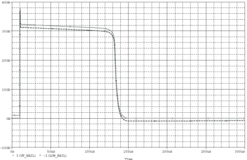
Figs. 3.6, 3.7 and 3.8 show the isolation procedure in case of the topologies proposed by Ribeiro et al. and by Bolognani et al., supposing a contemporary blowing of both fuses placed in the faulted leg.
Fig. 3.6 shows the currents in the DC bus rails, assuming as positive a current flowing in the directions of Fig. 3.5.
Fig. 3.6: DC bus rail currents for the isolation topologies proposed by Ribeiro et al and Bolognani et al.
At moment of fault, a short-circuit current through the DC bus rails rise to a very high level in few μs, due to the low leakage inductance offered by the DC link.
During the melting time, rail currents remain approximately constant and contribute to increase fuses temperature up to start the melting process: the difference between the two currents is the winding current, shown in Fig. 3.7.
The slow decrease of rails currents during the melting time is due to the DC bus voltage reduction, shown in Fig. 3.8, as a consequence of the capacitors discharge caused by the leg short circuit.
34 Fig. 3.7: Leg output current for the isolation topologies proposed by Ribeiro et al and Bolognani et al.
Fig. 3.8: DC Bus voltage for the isolation topologies proposed by Ribeiro et al and Bolognani et al.
As can be seen comparing amplitudes and times of Fig. 3.6 and 3.7, during fuses arching time, short-circuit current is brought to zero for first, while winding current for last: this different behavior is due to the different inductances of DC bus link and motor winding.
When the fuses try to stop winding current, a very high overvoltage is generated at winding terminals, and so at leg output, as depicted in Fig. 3.9; it should be noted that the other motor winding terminal not drawn in Fig. 3.5, has been connected to the midpoint of the DC bus during the simulation.
As reported in the literature [8], such over-voltages may cause windings turn-to-turn faults, even with small pulses (0.1 μs rise time, 3 p.u amplitude) in case of already present insulation degradation due to aging or inverter-fed operation.
35 Moreover, once the faulted leg has been electrically isolated from the DC bus rails, the over-voltage at its output may damage other part of the converter if the gate terminal is not also isolated by means of fuses.
Fig. 3.9: Leg output voltage, measured respect to the midpoint of the DC bus voltage, for the isolation topologies proposed by Ribeiro et al and Bolognani et al.
If additional freewheeling diodes are placed in parallel with fuses, as represented in Fig.3.5, waveforms equivalent to the previous ones can be obtained, as depicted in Figs. 3.10 to 3.13. The main difference is that, now, winding current can flow even after fuses have been blown, as can be seen comparing Figs. 3.10 and 3.11 to Figs. 3.6 and 3.7.
Winding energy is recovered and stored on the DC bus capacitors, as can be seen in Fig. 3.12, where the DC bus voltage slightly increase after fuses opening.
During simulations, DC bus capacitors are not connected to any power source in order to avoid that capacitor recharging, due to power source action, would hide the winding energy recovering.
36 Fig. 3.11: Leg output current for the proposed isolation topology.
Due to the additional freewheeling diodes presence, winding current is gently brought to zero in few milliseconds rather than in few tens nanoseconds, as evident from Figs. 3.11 and 3.10: the overvoltage at winding terminals and at inverter output is so eliminated, as shown in Fig. 3.13.
Fig. 3.12: DC Bus voltage for the proposed isolation topology.
Since winding current is not abruptly interrupted, a post-fault control strategy (which would not operate in open-phase mode) can take advantage of the residual winding current for restoring the pre-fault operating condition, if inverter is reconfigured soon after fuses blowing.