Sapienza Università di Roma
“Vito Volterra” Doctoral School in Astronomical, Chemical, Earth, Mathematical and Physical Sciences
The mechanics of phyllosilicates-bearing faults:
insights from field examples and
rock deformation experiments
by
Carolina Giorgetti
A Dissertation in
Structural Geology and Rock Mechanics submitted in fulfillment of the Requirements for the Degree of
Doctor of Philosophy
The dissertation of Carolina Giorgetti was reviewed and approved by
Cristiano Collettini
Associate Professor of Structural Geology Sapienza University of Rome, Italy Dissertation Advisor
Marie Violay
Assistant Professor of Rock Mechanics EPFL Lausanne, Switzerland
External Reviewer Tom M. Mitchell
Reader in Earthquake Geology and Rock Physics UCL London, United Kingdom
Abstract
Faults in the brittle crust are zones of weakness, whose reactivation depends on their friction and stress field acting on them. Over the last few decades, increasingly attention has been paid to characterize the frictional properties of phyllosilicates. These layer-structured minerals are indeed particularly weak, if compared with earliest laboratory experiments conducted on a vast gamut of crustal rocks showing friction almost independent of rock type and in the range of µ = 0.6-0.85. Phyllosilicates are not only inherently weak, but also unable to re-gain strength during inter-seismic period and to host earthquake nucleation. Moreover, previous studies have reported that even small amounts of phyllosilicates can drastically affect the overall frictional properties of fault rocks. These observations have strong implications for natural faults that involve different lithologies, including phyllosilicates-bearing rocks, and thus develop geometrical and lithological heterogeneities along dip and strike. The influence of these heterogeneities on fault mechanics is still poorly constrained.
Here, I integrate field observations and laboratory experiments on phyllosilicate-bearing faults to address different aspects regarding the role of phyllosilicates in fault mechanics. I examine questions such as: what is the minimum amount of phyllosilicates that drastically affects fault frictional properties? What is the mechanics of incipient faults within phyllosilicate-rich mechanical multilayers? What is the role of stress field orientation in the reactivation of phyllosilicate-bearing faults?
In Chapter 1, I experimentally investigate the frictional properties of talc-bearing faults in carbonates. Although talc has been found along carbonate-bearing faults, little is known about the amount of talc able to effectively weaken calcite fault gouges. In Chapter 2, I integrate field data and laboratory deformation experiments to study fault initiation and growth within clay-rich mechanical multilayers. Thus I give insight into the mechanics of clay-rich multilayers that is still poorly understood. In Chapter 3, I report on laboratory deformation experiments designed to evaluate the reactivation of pre-existing clay-bearing faults depending on their orientation within the stress field. The reactivation of pre-existing faults can be theoretically predicted assuming a zero-thickness fault. I attempt to validate frictional reactivation for a finite-thickness fault.
This dissertation provides insight into the mechanics of phyllosilicate-bearings faults. Firstly, I show that small amounts of talc fully weaken calcite-rich faults, developing an interconnected network of talc lamellae, and that even minor amounts of talc result in the evolution from velocity-neutral to velocity-strengthening behavior and in the reduction of
50% in frictional healing. Secondly, I demonstrate that the complex geometry of faults affecting mechanical multilayers results from the interplay between the mechanical properties of the involved lithologies and the presence of pre-existing discontinuities. Finally, I show that misoriented faults of finite thickness are weaker than theoretically predicted and that the assumption of a zero-thickness plane provides an upper bound for the stress required for the reactivation of a finite-thickness fault.
Riassunto
Faglie situate nella porzione fragile della crosta terrestre costituiscono zone di debolezza la cui riattivazione dipende dal loro attrito e dal campo dello sforzo che agisce su di esse. Negli ultimi decenni un’attenzione crescente è stata rivolta alla caratterizzazione delle proprietà frizionali dei fillosilicati. Tali minerali, caratterizzati da una struttura a strati, risultano infatti particolarmente deboli se paragonati con la maggior parte dei minerali costituenti la crosta terrestre. Inoltre i fillosilicati non sono capaci di riacquistare resistenza durante i periodi intersismici né di generare terremoti.
In aggiunta studi sperimentali riportano che la presenza di piccole quantità di fillosilicati può drasticamente influenzare le proprietà frizionali di rocce di faglia. Forti sono le implicazioni che questi studi sperimentali hanno sul comportamento di faglie naturali che contengono fillosilicati. Il coinvolgimento di diverse litologie in fenomeni di fagliamento comporta lo sviluppo di rocce di faglia fortemente eterogenee, il cui comportamento meccanico è ancora non del tutto compreso.
Nel presente lavoro integro osservazioni di terreno con esperimenti di laboratorio su faglie contenenti fillosilicati allo scopo di rispondere alle domande che seguono. Qual è il minimo quantitativo di fillosilicato che altera in modo significativo le proprietà frizionali della roccia di faglia? Qual è il comportamento meccanico di faglie incipienti in multistrati meccanici? Qual è il ruolo dell’orientazione del campo dello sforzo nella riattivazione di faglie contenenti fillosilicati?
Nel Capitolo 1 studio le proprietà frizionali di rocce di faglia contenenti talco che si sviluppano in carbonati. Nonostante il talco sia un fillosilicato particolarmente debole rinvenuto in faglie naturali in carbonati, non è noto come la sua presenza influenzi il comportamento meccanico della faglia. Nel Capitolo 2 descrivo l’inizio e lo sviluppo di faglie in multistrati meccanici ricchi in argilla, integrando dati di terreno con esperimenti di deformazione condotti in laboratorio. Il comportamento meccanico di tali multistrati è ad oggi scarsamente compreso. Nel Capitolo 3 riporto i risultati di esperimenti di deformazione sviluppati per studiare il ruolo dell’orientazione del campo dello sforzo sulla riattivazione di faglie contenenti argilla. Nonostante la riattivazione di faglie preesistenti sia spesso modellata analiticamente assumendo che la faglia sia un piano di spessore nullo, in natura la presenza di rocce di faglia fa sì che questa abbia uno spessore concreto. Per validare tali modelli analitici, ho simulato in laboratorio faglie di spessore finito
Questa tesi apporta ulteriori chiarimenti nella meccanica di faglie contenenti fillosilicati. Nel Capitolo 1, mostro che il 20% di talco abbassa significativamente l’attrito di faglie in carbonati, a seguito della concentrazione delle lamelle di talco lungo i piani di taglio. Inoltre l’aggiunta del 5% di talco comporta la transizione da un comportamento velocity-neutral ad uno velocity-strengthening ed una riduzione del 50% del frictional healing. Nel Capitolo 2 dimostro che le geometrie complesse sviluppate da faglie in multistrati meccanici risulta dall’interazione delle proprietà meccaniche del multistrato con discontinuità preesistenti. Infine nel Capitolo 3 mostro che faglie male orientate di spessore finito sono più deboli di quanto teoricamente previsto, pertanto assumere che la faglia sia un piano di spessore nullo può condurre ad una sovrastima dello sforzo necessario alla riattivazione.
Preface
The work presented in the main chapters of the dissertation is a result of collaboration with Sapienza University of Rome, INGV (Istituto Nazionale di Geofisica e Vulcanologia) and University of Perugia. The data collection, analysis, and writing are my own work. Chapters 1 and 2 have been peer-reviewed and can be found in the literature with the following citations:
Giorgetti, C., B. M. Carpenter, and C. Collettini (2015), Frictional behavior of talc-calcite mixtures, Journal of Geophysical Research Solid Earth, 120, 6614-6633, doi:10.1002/2015JB011970.
Giorgetti, C., C. Collettini, M. M. Scuderi, M. R. Barchi, and T. Tesei (2016), Fault geometry and mechanics of marly carbonate multilayers: An integrated field and laboratory study from the Northern Apennines, Italy, Journal of Structural Geology, 93, 1-16, doi:10.1016/j.jsg.2016.10.001.
Chapter 3 is currently being prepared for submission with the following author list: Giorgetti, C., T. Tesei, M. M. Scuderi and C. Collettini.
“Nell’analisi delle idee (ben inteso nel campo delle scienze naturali) non è sempre proficuo seguire l’ordine in cui esse si presentano storicamente. Molto spesso noi poniamo il piede nell’edificio sconosciuto d’un nuovo ordine di idee per una porticina secondaria, arriviamo dapprima in un’ala laterale e ci vuole molto tempo prima di essere orientati, prima di aver trovato l’entrata principale e di aver scelto una posizione che ci permetta di contemplare l’architettura dell’insieme dalla giusta prospettiva.”
“Der Geist der Naturwissenschaft” Erwin Schrödinger, 1947
Table of Contents
Introduction ... 1
Chapter 1. Frictional behavior of talc-calcite mixtures ... 6
Abstract ... 6 1.1. Introduction ... 7 1.2. Experimental method ... 9 1.2.1. Sample description ... 9 1.2.2. Experimental procedure ... 9 1.2.3. Microscopy Observations ... 14 1.3. Results ... 15 1.3.1. Mechanical data ... 15
1.3.1.1. Frictional behavior at 5 MPa normal stress ... 15
1.3.1.2. Frictional behavior at 20 and 50 MPa normal stress ... 17
1.3.2. Microstructural observations ... 20
1.4. Discussion ... 23
1.4.1 Integration of mechanical data and microstructures ... 23
1.4.2 Comparison to previous data ... 27
1.4.3 The Mechanisms of frictional healing ... 31
1.5. Conclusion ... 35
Acknowledgments ... 35
1.6. Supporting information ... 37
Chapter 2. Fault geometry and mechanics of marly carbonate
multilayers: an integrated field and laboratory study from the
Northern Apennines, Italy ... 44
Abstract ... 44
2.1. Introduction ... 45
2.2. Geological framework ... 47
2.3.1. Theoretical framework for field observations ... 49
2.3.2 Laboratory investigations ... 50
2.3.2.1 Triaxial deformation experiments ... 52
2.3.2.2 Biaxial deformation experiments ... 54
2.4. Structural data ... 56
2.4.1. Fault architecture: from incipient to “mature” faults ... 57
2.4.2. Stress field orientation and angles of faulting ... 61
2.5. Laboratory rock deformation data ... 63
2.5.1. Strength and fracture permeability of cohesive limestones ... 63
2.5.2. Strength of incohesive marls ... 64
2.6. Discussion ... 66
2.6.1. Fault initiation ... 66
2.6.1.1 Fault initiation in limestone ... 66
2.6.1.2 Fault initiation in marls ... 67
2.6.1.3 Fault initiation in the mechanical multilayer ... 68
2.6.2. Fault growth and angles of fault reactivation ... 68
2.6.3. Fluid flow controlled by fracture and fault permeability ... 71
2.7. Conclusions ... 72
Acknowledgments ... 73
Chapter 3. Fault reactivation: insights from triaxial saw-cut
experiments ... 74
Abstract ... 74 3.1. Introduction ... 75 3.2. Methods ... 77 3.2.1. Triaxial experiments ... 77 3.2.2. Friction experiments ... 793.2.3. Triaxial saw-cut experiments ... 81
3.3.2. Stress versus displacement evolution curves in triaxial cut experiments:
saw-cut reactivation versus new fracture development ... 84
3.3.3. Microstructural evolution during reactivation ... 87
3.4. Discussion ... 89
3.4.1. Integration of mechanical data and microstructures ... 89
3.4.2. Fault reactivation: theory versus experimental data ... 89
3.4.3. The dynamics of fault reactivation ... 92
3.4.4. Implications for natural faults ... 95
3.5 Conclusions ... 96
Acknowledgments ... 96
Conclusion ... 97
Bibliography ... 99
Appendix A. Technical corrections to mechanical data from triaxial and
triaxial saw-cut experiments ... 117
A.1. Elastic stretch of the load frame on the vertical axis as a function of confining pressure ... 117
A.2. Strength of the polyolefin jacket used in triaxial saw-cut experiments ... 118
Appendix B. Python scripts developed to analyze field and laboratory
data ... 120
B.1. Local stress field and angle between faults and maximum principal stress from field data ... 120
B.2. Data analysis of triaxial saw-cut experiments in which slip occurs within the saw-cut ... 123
Appendix C. Friction and scale-dependent deformation processes of large
experimental carbonate faults ... 126
Appendix D. Structural Disorder of Graphite and Implications for
Graphite Thermometry ... 139
Appendix E. Dynamics of fault slip near the stability transition
combining laboratory and numerical experiments ... 159
Appendix F. List of experiments... 160
Introduction
Faults in the brittle crust are the expression of localized strain mostly due to tectonic loading. Accumulated strain, clearly observable in exhumed faults, is the evidence of slip experienced by faults. How this slip is accommodated ranges from sudden and repeated to continuous and stable. Particularly, a sudden slip on a fault results from an abrupt release of stored elastic energy that generates an earthquake (Reid, 1910; Brace and Byerlee, 1966). This elastic energy is released only when the decrease of fault frictional strength with displacement exceeds the elastic unloading of the surrounding (Rice, 1983; Scholz, 2002). Additionally, the occurrence of repeated earthquakes on a fault requires that the fault re-strengthens after each sudden slip (e.g., Dieterich, 1972; Marone, 1998a; Tadokoro and Ando, 2002; Li et al., 2003). Stable versus unstable slip behavior significantly depends on the frictional properties of the fault and the mechanical properties of its surrounding and, consequently, by the lithology involved in the deformation processes.
Laboratory experiments on rock mechanics effectively simulate slip on fault portions at small scale. Over the last few decades, increasingly attention has been paid to characterize the frictional properties of phyllosilicates and phyllosilicates-bearing fault rocks. These layer-structured minerals are particularly weak (e.g., Brown et al., 2003; Moore and Lockner, 2008; Ikari et al., 2009a; Lockner et al., 2011), if compared with earliest laboratory experiments, conducted on a vast gamut of crustal rocks showing friction almost independent of rock type and in the range of µ = 0.6 - 0.85 (Byerlee, 1978).
Early laboratory investigations revealed that rock sliding friction at sub-seismic velocity depends on sliding velocity (Dieterich, 1978) and that static friction depends on time of stationary contact (Dieterich, 1972). Both these aspects are well constrained in a laboratory-derived empirical relation called the rate- and state-dependent friction law (Dieterich, 1979; Ruina, 1983). In the framework of the rate- and state- friction, the velocity dependence of sliding friction describes fault seismic potential and the time dependence of static friction (i.e. the healing rate) describes inter-seismic fault re-strengthening. Velocity-weakening behavior (i.e. an increase in sliding velocity induces a decrease in sliding friction) implies earthquake rupture nucleation during pre-seismic fault acceleration. Contrarily, velocity strengthening behavior (i.e. an increase in sliding velocity induces an increase in sliding friction) favors rupture arrest and aseismic creep. In addition, earthquake nucleation requires the re-strengthening of the fault during the inter-seismic locking. In general, high friction (i.e., µ = 0.6 - 0.85) in rocks is associated with velocity-weakening behavior and high healing rate (e.g.,
Ikari et al., 2011; Carpenter et al., 2016b). Oppositely, phyllosilicates are characterized by velocity-strengthening and near-zero healing rate (e.g., Ikari et al., 2009a; Tesei et al., 2012; Carpenter et al., 2016b). Experimental studies have not only shown the intrinsic weakness of phyllosilicates but also the significant influence that even small amounts of them in fault rocks exert on the overall fault frictional properties (e.g., Collettini et al., 2009a; Tembe et al., 2010; Moore and Lockner, 2011; Tesei et al., 2014). Striking similarity between microstructures produced during experiments and microstructures of natural fault rocks suggests that shear experiments well reproduce processes occurring on natural faults.
However, faults are much more complex structure whose reactivation not only depends on rock frictional properties but also on the orientation and the magnitude of the stress field (e.g., Sibson, 1985). Generally, fault architecture consists of a fault core, up to few meter thick, surrounded by complex damage zones (e.g., Caine et al., 1996; Ben-Zion and Sammis, 2003; Faulkner et al., 2011). In turn, the fault core consists of lenses of fault rocks bounded by localized slip zones no more than few centimeters thick (e.g., Sibson, 1977; Koopman et al., 1983; Sibson, 2003; Tesei et al., 2013; Collettini et al., 2014a). Differently, phyllosilicate-rich fault rocks develop fault cores up to 1 km thick containing high strain zones up to few meters thick where the deformation is homogeneously distributed (e.g., Collettini and Holdsworth, 2004; Faulkner et al., 2003; Tesei et al., 2013). As a consequence, a layered crust characterized by the presence of different lithologies, including phyllosilicates-rich layer, involve the development of faults in which localized and distributed deformation coexist. Geometrical and lithological heterogeneities along fault dip and strike results in frictional properties variability within the fault core. In addition, fault evolution with accumulating strain results in frictional properties that change over time.
Similarly, on a smaller scale, stratigraphy exerts a major control on fault geometry (e.g., Peacock and Sandersons, 1992; Ferrill and Morris, 2008). The stratigraphic alternation of lithologies, with variable content of phyllosilicates, results in the alternation of layers with differing mechanical properties. Faults affecting these mechanical multilayers, especially at incipient stages, develop complex geometries resulting from the interplay between the strength and the thickness of the layers and the orientation of the stress field with respect to the layering. Again, the high heterogeneity of these faults in space and time strongly influences their frictional properties and their slip behavior.
natural faults and laboratory experiments to contribute towards filling this knowledge gap. The thesis comprises three chapters in which I present my own research developed during the PhD. In Appendices I report technical details of the methodologies that I used and scientific collaborations in which I took part. Rock deformation experiments reported in Chapters 1, 2 and 3 and Appendices C, D and E were conducted with the BRAVA apparatus (Collettini et al., 2014b) installed at the High Pressure - High Temperature laboratory of INGV (Rome, Italy).
In Chapter 1 I investigate the role of increasing talc content on the frictional properties of calcite-rich experimental faults. Talc is one of the weakest amongst phyllosilicates and it has been found along many mature faults. In particular, the precipitation of talc and calcite, due to the stress-induced dissolution of dolomite in the presence of silica-rich fluids, has been documented along the Zuccale low-angle normal fault in Italy (Collettini et al., 2009a). The development of talc in magnesium-rich carbonates may significantly weaken faults in the brittle crust. To constrain the minimum amount of talc that can effectively weaken calcite fault gouge, I conducted shear experiments on binary mixtures of talc and calcite powders, systematically increasing the talc content. I examine the frictional strength, the velocity dependence and the frictional healing of the mixtures, integrating the mechanical results with microstructures of the sheared gouges. I show that an interconnected network of talc, developed by adding a 20% wt. talc, significantly weakens the calcite gouge, causing a reduction of 70% wt. in strength, a markedly velocity-strengthening behavior and an almost zero frictional healing. Interestingly, 5 % wt. talc dispersed in the calcite gouge results in a reduction of 50% in frictional healing, pointing out the possible contribution of chemical mechanisms to frictional healing even at shallow conditions.
In Chapter 2 I explore brittle faulting in mechanical multilayers through the integration of structural geology in the field and rock mechanics in the laboratory. Despite the complex geometries of faults in multilayers have been largely documented in outcrop, their mechanics is still a matter of debate and considered as a frontier research topic due to their economical and societal impact. Clay-rich multilayers potentially constitute both seals for hydrocarbons or unconventional reservoirs and a comprehensive understanding of their mechanical behavior is required to assess the risks associated to human activity, as drilling, well exploitation or injection. Here, I present a new approach that combines the structural characterization of outcropping faults in multilayers with the laboratory deformation of involved lithologies. The studied outcrop consists of clay-rich multilayers characterized by the alternation of pelagic limestone and clay-rich marl, affected by mesoscale faults from millimetric to decametric
displacement. The local stress field was reconstructed from the orientation of faults, fractures and kinematic indicators. The angle between the faults and the maximum principle stress provides a mechanical characterization of the outcropping faults. After collecting representative samples of limestone and marl, the strength of the limestone was evaluated via triaxial experiments and the sliding friction of marl via shear experiments. I constrained the mechanical evolution of faults from incipient complex staircase geometry to well-developed core with SCC’ fabric through the integration of field and laboratory data. The angles of fault initiation in limestone and marl layers are consistent with the respective failure and frictional strength or with the reactivation of pre-existing fractures in limestone and sedimentary foliation in clay-rich marl. The angles of reactivated faults characterized by a clay-rich fault core are consistent with the laboratory-derived sliding friction of marl. Furthermore, field observations demonstrate that brittle faulting enhances fluid circulation within low-permeability multilayers.
In Chapter 3 I investigate the role of stress field orientation on the reactivation of pre-existing faults. Theoretically the reactivation is controlled by the sliding friction of the fault plane, the orientation and the magnitude of the stress field and it is upper bounded by the strength of the surrounding rock. To investigate the reactivation of a pre-existing fault, I designed and developed the triaxial saw-cut configuration (e.g., Byerlee,1978) within BRAVA (Collettini et al., 2014b). I placed a layer of granular clay-rich gouge within a saw-cut realized in a cylinder of intact sandstone to simulate a pre-existing fault in a rock volume. Systematically changing the orientation of the saw-cut to the maximum principal stress, I evaluated the role of stress field orientation in fault reactivation. In parallel with the collection of mechanical data, I performed microstructural analyses on sheared experimental faults at different amount of displacement to evaluate their micro-mechanical evolution during reactivation. I show that the reactivation occurs via stress drops and it is related to the transition from distributed to localized deformation along shear planes. Fault reactivation versus new fracture development observed during our triaxial saw-cut experiments is well predicted by the single plane of weakness theory (e.g., Jaeger,1960), that is a generalization of the Mohr-Coulomb failure criterion. However, I show that the assumption of a zero-thickness plane provides an upper bound on the stress required for the reactivation of finite thickness fault.
In Appendix A, I carefully describe technical corrections that I developed to analyze the data collected from triaxial and triaxial saw-cut experiments. Particularly, I evaluated the
correct the displacement applied to sample with or without saw-cut. Moreover, I evaluated the strength of the polyolefin jacket used in triaxial saw-cut experiments to correct the differential stress required to shear within the gouge layer. In Appendix B, I reported the code that I developed to analyze the data collected in the field described in Chapter 2 and the data recorded during triaxial saw-cut experiments in which shear occurs within the gouge layer described in Chapter 3.
Appendices C and D are papers, published and under review respectively, in which I am coauthor. In Appendices C, we reported on frictional behavior and deformation products of shear experiments on large faults, i.e. 20 cm x 20 cm bare surfaces. I contributed performing experiments and collecting microstructural observations. In Appendices D, we reported on shear experiments on highly-crystalline powdered graphite to investigate the disordering induced by brittle shear. I contributed planning and performing all the experiments. Appendix E is an abstract on an on-going project on the dynamics of fault slip near the stability transition. Finally, Appendix F is the complete list of the experiments that I performed during my PhD.
Chapter 1.
Frictional behavior of talc-calcite mixtures
Abstract
Faults involving phyllosilicates appear weak when compared to the laboratory-derived strength of most crustal rocks. Amongst phyllosilicates, talc, with very low friction, is one of the weakest minerals involved in various tectonic settings. As the presence of talc has been recently documented in carbonate faults, we performed laboratory friction experiments to better constrain how various amounts of talc could alter these fault’s frictional properties. We used a biaxial apparatus to systematically shear different mixtures of talc and calcite as powdered gouge at room temperature, normal stresses up to 50 MPa and under different pore fluid saturated conditions, i.e. CaCO3-equilibrated water and silicone oil. We performed
slide-hold-slide tests, 1-3000 seconds, to measure the amount of frictional healing and velocity-stepping tests, 0.1-1000 µm/s, to evaluate frictional stability. We then analyzed microstructures developed during our experiments. Our results show that with the addition of 20% talc the calcite gouge undergoes a 70% reduction in steady-state frictional strength, a complete reduction of frictional healing and a transition from weakening to velocity-strengthening behavior. Microstructural analysis shows that with increasing talc content, deformation mechanisms evolve from distributed cataclastic flow of the granular calcite to localized sliding along talc-rich shear planes, resulting in a fully interconnected network of talc lamellae from 20% talc onwards. Our observations indicate that, in faults where talc and calcite are present, a low concentration of talc is enough to strongly modify the gouge’s frictional properties and specifically to weaken the fault, reduce its ability to sustain future stress drops and stabilize slip.
1.1. Introduction
Geological studies show that mature fault zones can contain a variable amount of phyllosilicates (e.g., Wintsch et al., 1995; Vrolijk and van der Pluijm, 1999; Faulkner et al., 2003; Collettini and Holdsworth, 2004; Jefferies et al., 2006; Fagereng and Sibson, 2010). Talc, in particular, has been documented in exhumed subduction thrust faults (e.g., Peacock, 1987; Bebout and Barton, 2002; King et al., 2003), in oceanic transform faults (d’Orazio et al., 2004) and in oceanic detachments (e.g., Escartín et al., 2003; Schroeder and John, 2004). Drilling projects have reported the presence of talc within active traces of major faults at depth, such as the San Andreas fault in California (Moore and Rymer, 2007) and the Moresby fault in Papua New Guinea (e.g., Floyd et al., 2001; Kopf, 2001; Roller et al., 2001; Taylor and Huchon, 2002). Talc has also been found along exhumed low angle normal faults in Italy (Collettini et al., 2009b; Viti and Collettini, 2009) and in the Cyclades (Grasemann and Tschegg, 2012). In subduction thrust faults, oceanic fracture zones and oceanic detachments, talc is typically derived from the metamorphic alteration of ultramafic rocks with silica-saturated hydrothermal fluids (e.g., Manning, 1995; Boschi et al., 2006; Moore and Rymer, 2007). In sedimentary rocks, talc development is the result of dissolution of dolomite and interaction with silica-rich fluids (Collettini et al., 2009b).
The presence of talc and other phyllosilicates within mature fault zones strongly influences the strength and slip behavior of those faults. Early laboratory experiments conducted on a vast gamut of rocks showed that friction was almost independent of rock type and is in the range of µ = 0.6-0.85 (Byerlee, 1978). Hereafter, we referred to rocks and faults whose coefficient of friction is within this range as strong, as opposed to rocks and faults whose coefficient of friction is half of or less than the values in this range, that are thus considered weak. The laboratory prediction of strong faults, with high friction, seems to be consistent with measurements of crustal stress levels in deep boreholes (Townend and Zoback, 2000) and the analysis of earthquake focal mechanisms (Collettini and Sibson, 2001). However in the last decade there is growing evidence for the presence of mechanically weak faults: including strike-slip faults, like the San Andreas (Hickman and Zoback, 2004; Moore and Rymer, 2007; Schleicher et al., 2010; Carpenter et al., 2011; Lockner et al., 2011), low-angle normal faults (Numelin et al., 2007; Collettini et al., 2009b) and thrust faults (Kopf and Brown, 2003; Ikari et al., 2009b; Tesei et al., 2014). In all of these structures, fault weakness is inferred to result from the development of through-going phyllosilicate-rich zones within the fault zone at the expense of the strong mineral phases. The importance of the distribution of weak and strong minerals in fault rocks has been further confirmed by laboratory
experiments showing that intact, foliated samples are extremely weak when compared to powders derived from the same samples (e.g., Collettini et al., 2009a). Phyllosilicates are characterized by a strong mechanical anisotropy, due their layered structure, that leads to the development of efficient planes of weakness, when the layers are favorably iso-oriented with respect to the shear.
Important questions for fault mechanics that remain are: what percent of a weak mineral phase is capable of changing fault strength and how does the presence of weak mineral phases influences fault slip behavior? Experimental studies conducted on intact cores of slightly serpetinized peridotites have shown that small amounts of weak phase, i.e. 9% of lizardite and chrysotile, strongly affect the mechanical properties of peridotite, resulting in a mechanical behavior characteristic of pure serpentinites (Escartín et al., 2001). Similarly, metasomatic growth of talc observed during shear experiments strongly weakens gouges, developing through-going shear surfaces (Hirauchi et al., 2013). Previous experiments on mixtures of strong granular materials and weak platy minerals have highlighted the role of phyllosilicates in weakening granular fault gouges (e.g., Bos and Spiers, 2000; Tembe et al., 2010; Moore and Lockner, 2011). For example in quartz/montmorillonite mixtures, 50% of montmorillonite reduces friction, measured at about 9 mm of shear displacement, from 0.75 to 0.26 (Tembe et al., 2010). In quartz/talc mixtures, 50% of talc is responsible of a friction drop, measured at about 3.5 mm of shear displacement, from 0.7 to 0.3 and promotes velocity-strengthening behavior, i.e. increasing friction with increasing velocity (Moore and Lockner, 2011). The presence of weak platy minerals also reduces the ability of gouges to regain strength during non-shearing periods (Niemeijer and Spiers, 2006; Carpenter et al., 2011; Tesei et al., 2012).
In this manuscript we investigate the effect of increasing talc content on the frictional and healing properties of calcite by running experiments on binary mixtures of calcite and talc and looking at the microstructures developed within the experimental faults. Our study provides insights on fault slip behavior, not only for talc rich-faults developed within carbonates, but also for those forming from serpentinites where calcite can be present along the fault zone due to hydrothermal cementation (e.g., Bernoulli and Weissert, 1985).
1.2. Experimental method
1.2.1. Sample description
Synthetic gouge mixtures used in this study were prepared from calcite and talc minerals in various proportions by weight. Calcite gouge was prepared from locally sourced Carrara Marble (>98% CaCO3) that was crushed and sieved to < 125 µm grain size (Figures S1 and
S2). Talc was prepared by separating talc grains from a talc-rich schist from Balmat, New York, and was provided by Ward’s Science. It was also crushed and sieved to < 125 µm grain size (Figures S1 and S2).
We performed friction experiments in a servo-controlled biaxial testing apparatus installed in the High Pressure-High Temperature Laboratory at the INGV in Rome, Italy (Collettini et al., 2014b). Stainless steel load cells continuously measure applied force with 0.03 kN resolution and LVDT sensors continuously measure load point displacements with 0.1 µm resolution. Two layers of simulated fault gouge were placed in-between three grooved sliding blocks, in a double-direct shear configuration (e.g., Dieterich, 1972; Mair and Marone, 1999; Ikari et al., 2011). The two gouge layers, each with an initial ~5-mm uniform thickness measured before the samples were loaded, were constructed in order to have a 5×5-cm uniform area, that is maintained constant throughout the experiment (Figure 1.1a, inset).
1.2.2. Experimental procedure
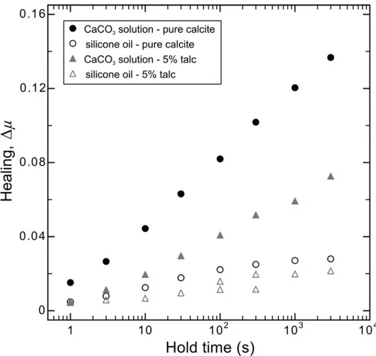
Experiments were performed at room temperature and under CaCO3-equilibrated water
saturated conditions, except for two experiments, which were saturated with silicone oil. Initially, we ran a suite of 14 friction experiments under a constant normal stress of 5 MPa, in which talc content was systematically increased from 0% to 100%, in order to characterize the frictional behavior of the binary mixtures. Subsequently, we ran 4 more experiments under higher normal stress, i.e. 20 MPa and 50 MPa, focusing on 5 % and 20 % talc samples.
The experimental sample assembly was loaded into the testing apparatus and placed within a plastic membrane that was filled with the saturating fluid after the application of an initial normal load. Our experiments were performed under drained conditions. Initially we applied a normal stress of 1 MPa and allowed the sample to saturate for 30 minutes with DI water that had been brought into equilibrium with CaCO3.
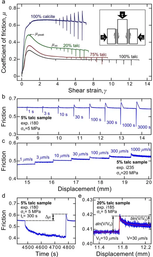
Figure 1.1. a) Friction plotted against shear strain for selected slide-hold-slide friction experiments, showing the
evolution of friction for different talc contents. During the “run-in” phase, peak friction is attained (µpeak) and then evolves to a steady-state value (µss), as shown in the 20% talc sample. After the run-in, the slide-hold-slide and velocity step sequences are started. Inset shows the double-direct shear configuration in which three stainless steel forcing blocks sandwich two identical layers of experimental fault gouge. b) Details of friction versus displacement for a slide-hold-slide sequence. c) Details of friction versus displacement for a velocity step sequence. d) Details of friction versus time for a 300 s hold. Δµ is the difference between the peak value of
Layer compaction was monitored checking, after 30 minutes, the achievement of a steady-state value of layer thickness, that depends on the amount of compaction each gouge undergoes. Subsequently, normal stress was increased to the target value, i.e. 5, 20 or 50 MPa, and the sample was subjected to a shear displacement “run-in” of ~7.5-8.5 mm by imposing a load velocity of 10 µm/s to the vertical piston. The “run-in” phase allows for the development of a steady-state friction (Figure 1.1a). Following steady shear, we imposed a series of computer-controlled changes in sliding velocity to test the time- and velocity-dependence of friction (Figure 1.1); we evaluated changes in friction in the context of rate- and state-dependent friction (e.g., Marone, 1998b).
The coefficient of friction (µ) was calculated from the Coulomb criterion by dividing half of the vertical load (two gouge layers) by the horizontal load, i.e. the shear stress by the normal stress, and assuming no cohesion. The average shear strain within the layer was calculated by dividing shear displacement increments by the measured layer thickness and summing. The displacement values of the vertical and horizontal load points were corrected for the elastic stretch of each load frame, taking into account that the machine stiffness is 1283 kN/mm on the horizontal axis and 928.5 kN/mm on the vertical axis.
Following steady shear, we performed slide-hold-slide and velocity-stepping sequences (Table 1.1). Slide-hold-slide tests consist of a sequence of slide-hold-slide cycles: 75 s of sliding at 10 µm/s was followed by a hold period, th, ranging from 1 to 3000 s, during which
sliding is halted and subsequently resumed (Figure 1.1a, b and d), following the same procedure as in Carpenter et al. (2011) and Tesei et al. (2012). The amount of frictional healing (Δµ) is measured as the difference between the peak friction measured upon re-shear after each hold and the pre-hold steady-state friction (Δµ), as in previous work by Marone (1998), Richardson and Marone (1999), and Frye and Marone (2002). Steady-state friction is generally identical before and after the hold. However, few samples showed a slight strain related trend in plotting friction as a function of shear strain. We removed these trends in order to measure a more precise Δµ. Frictional healing rates (β) was calculated as
𝛽 = ∆𝜇 ∆ log)* t, (1.1)
During velocity-stepping tests, we imposed velocity step sequences of 0.1 to 1000 µm/s with a constant displacement of 750 µm at each step. In four experiments we also ran velocity step sequence of 1 to 1000 µm/s after the slide-hold-slide sequence. Each velocity step consists of a near instantaneous step changes in sliding velocity from V0 to V (e.g., Dieterich,
the new sliding velocity held constant until a new steady-state shear stress level was attained (Figure 1.1c and e). The instantaneous change in friction scales as the friction parameter aln(V/V0), where a is an empirical constant defined as the direct effect (e.g., Ruina, 1983).
The subsequent drop to a new steady-state value of friction scales as the friction parameter bln(V/V0), where b is an empirical constant defined as the evolution effect (e.g., Ruina, 1983).
The velocity dependence of steady-state friction (a-b) is defined as 𝑎 − 𝑏 = ∆011
23 4 45 (1.2)
where Δµss is the change in steady-state friction. Positive values of (a-b), defining
velocity-strengthening behavior, indicate that stable sliding should be expected. Negative values of (a-b), i.e. velocity-weakening behavior, are a requirement for the nucleation of slip instability (e.g., Dieterich and Kilgore, 1994; Marone, 1998b; Scholz, 1998).
The collected data were subsequently modeled with the Dieterich, time-dependent, version of the rate- and state- friction constitutive law and evolution equation (Dieterich, 1979)
𝜇 = 𝜇*+ 𝑎 𝑙𝑛 44 5 + 𝑏 ln 45; <= , ?; ?@ = 1 − ;4 <= (1.3)
where V0 is a reference velocity and µ0 is the steady-state friction at V = V0. Dc is the
critical slip distance and θ is the state variable (units of time) that expresses the effective contact time derived from the ratio of a critical slip distance Dc to slip velocity V. The state
variable θ is thought to represent the average lifetime of asperity contacts that control friction and the critical slip distance Dc represents the displacement over which the population of
asperity contacts are renewed (Marone and Kilgore, 1993; Scholz, 1998). To model our data, the constitutive law and the evolution equation are coupled with an equation describing the compliant coupling between the frictional surface and its surroundings, i.e. the interaction of the sample with its elastic load frame
?0
?@ = 𝑘 𝑉DE 𝑉 (1.4)
where Vlp is the velocity measured at the displacement control point and k is stiffness of the
testing apparatus and the sample blocks, normalized by the normal stress, in units of coefficient of friction per displacement. We simultaneously solved the Dieterich constitutive law and evolution equation, with elastic coupling equation as a constraint, by using a fifth-order Runge-Kutta numerical integration. The constitutive parameters a, b and Dc were
nonlinear inverse problem (e.g., Reinen and Weeks, 1993; Blanpied et al., 1998; Saffer and Marone, 2003).
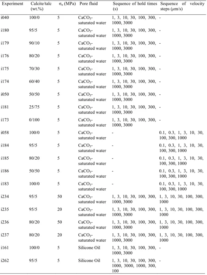
Table 1.1. List of experiments. All experiments were conducted at a background sliding velocity of 10 µm/s. Experiment Calcite/talc
(wt.%)
σn (MPa) Pore fluid Sequence of hold times
(s) Sequence of velocity steps (µm/s) i040 100/0 5 CaCO3 -saturated water 1, 3, 10, 30, 100, 300, 1000, 3000 - i180 95/5 5 CaCO3 -saturated water 1, 3, 10, 30, 100, 300, 1000, 3000 - i179 90/10 5 CaCO3 -saturated water 1, 3, 10, 30, 100, 300, 1000, 3000 - i176 80/20 5 CaCO3 -saturated water 1, 3, 10, 30, 100, 300, 1000, 3000 - i175 70/30 5 CaCO3 -saturated water 1, 3, 10, 30, 100, 300, 1000, 3000 - i174 60/40 5 CaCO3 -saturated water 1, 3, 10, 30, 100, 300, 1000, 3000 - i050 50/50 5 CaCO3 -saturated water 1, 3, 10, 30, 100, 300, 1000, 3000 - i181 25/75 5 CaCO3 -saturated water 1, 3, 10, 30, 100, 300, 1000, 3000 - i173 0/100 5 CaCO3 -saturated water 1, 3, 10, 30, 100, 300, 1000, 3000 - i058 100/0 5 CaCO3 -saturated water - 0.1, 0.3, 1, 3, 10, 30, 100, 300, 1000 i184 95/5 5 CaCO3 -saturated water - 0.1, 0.3, 1, 3, 10, 30, 100, 300, 1000 i185 80/20 5 CaCO3 -saturated water - 0.1, 0.3, 1, 3, 10, 30, 100, 300, 1000 i186 50/50 5 CaCO3 -saturated water - 0.1, 0.3, 1, 3, 10, 30, 100, 300, 1000 i183 100/0 5 CaCO3 -saturated water - 0.1, 0.3, 1, 3, 10, 30, 100, 300, 1000 i234 95/5 50 CaCO3 -saturated water 1, 3, 10, 30, 100, 300, 1000, 3000 1, 3, 10, 30, 100, 300, 1000 i235 95/5 20 CaCO3 -saturated water 1, 3, 10, 30, 100, 300, 1000, 3000 1, 3, 10, 30, 100, 300, 1000 i236 80/20 50 CaCO3 -saturated water 1, 3, 10, 30, 100, 300, 1000, 3000 1, 3, 10, 30, 100, 300, 1000 i237 80/20 20 CaCO3 -saturated water 1, 3, 10, 30, 100, 300, 1000, 3000 1, 3, 10, 30, 100, 300, 1000
i161 100/0 5 Silicone Oil 1, 3, 10, 30, 100, 300, 1000, 3000
- i262 95/5 5 Silicone Oil 1, 3, 10, 30, 100, 300,
1000, 3000, 1000, 300, 100
At the end of the slide-hold-slide tests, parts of the gouge layers were collected, dried at room temperature and preserved in epoxy resin, in order to obtain thin sections parallel to the sense of shear for microstructural analysis.
1.2.3. Microscopy Observations
Microstructural observations were performed with a JEOL JSM-6500F thermal field emission scanning electron microscope, installed in the Electron Microscopy Laboratory at the INGV in Rome, Italy. All the micrographs presented in this manuscript are backscattered electron (BSE) images. Specifically, we collected photo mosaics at high magnification of the entire thin section thickness and micrographs of thin section details at higher magnification.
1.3. Results
1.3.1. Mechanical data
1.3.1.1. Frictional behavior at 5 MPa normal stress
Our strength results, with the exception of pure calcite, indicate an evolution curve of the coefficient of friction characterized by a distinct peak (µpeak) and subsequent decay to a
steady-state value (µss) with increasing displacement (Figure 1.1a and Figure S3b). All the
values of steady-state friction reported and discussed hereafter are measured during slide-hold-slide experiments. All the mixtures, at a sliding velocity of 10 µm/s, have values of the coefficient of friction that range between pure calcite value, i.e. µpeak = µss ≈ 0.66, and pure
talc value, i.e. µpeak ≈ 0.30 and µss ≈ 0.20 (Figure 1.2).
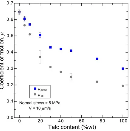
Figure 1.2. Friction of talc/calcite binary mixtures as function of talc content in experiments carried out at
sliding velocity of 10 µm/s and at constant normal stress of 5 MPa. Friction systematically decreases with increasing talc content. The values reported for 0%, 5%, 20%, 50% and 100% are the average between slide-hold-slide experiments and velocity step experiments, the error bar thus indicates the difference between the two values. Whereas the values reported for all the other mixtures result from slide-hold-slide experiments. For the strain and the displacement at which the values were measured see Figure S3.
The coefficient of friction decreases systematically with increasing talc content, but the trend of friction reduction between the two end-members is not linear. There is a significant drop in friction (70% in µss) between 0 and 20% talc, and a more gradual decrease at higher
tends to increase from 0 to 0.18 with the progressive addition of up to 50% talc and then to decrease slightly for higher talc contents. Strain at which the coefficient of friction reaches peak values tends to increase with increasing talc content, from γ = 0.85 to γ = 1.88, whereas strain at which friction reaches steady-state values tends to slightly decrease with increasing talc content, from γ = 6.41 to γ = 1.88 (Figure S3a).
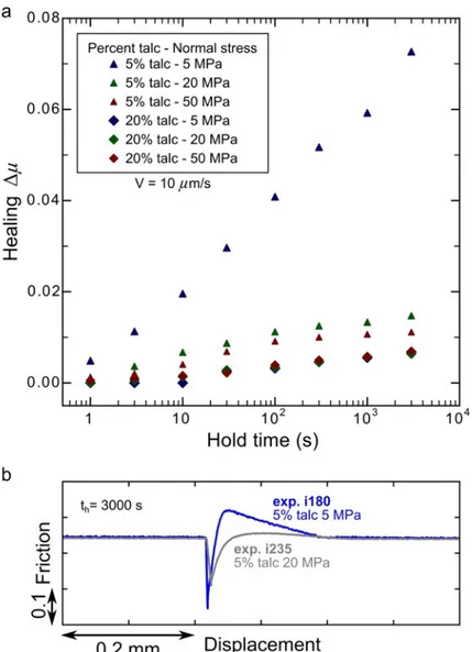
Figure 1.3 shows healing results for our experiments at normal stress of 5 MPa. A content of 5% of talc is enough to cause a 50% drop in the rate of frictional healing, i.e. from β ≈ 0.0361 to β ≈ 0.0196. The healing rate of 10% talc sample is lower (β ≈ 0.0124) and it is nearly zero for samples containing ≥ 20% talc. In samples with talc ranging from 20% to 50%, the rate of frictional healing ranges from 0.0021 < β < 0.0035. For the gouges containing 75% and 100% talc the healing rate is β ≈ 0.0010. Like for frictional strength, there is a significant and sharp, almost linear, drop in healing rate between 0 and 20% talc, and a slower degradation at higher talc contents.
Figure 1.3. Frictional healing as function of hold time for different talc contents in experiments carried out at
sliding velocity of 10 µm/s and at constant normal stress of 5 MPa. A small amount of talc strongly reduces frictional healing.
Concerning the velocity dependence of friction (Figure 1.4), pure calcite gouge shows variable behavior from velocity-strengthening to velocity-weakening, whereas all the other gouges exhibit a clear velocity strengthening behavior (Figure 1.4a). The trend of (a-b) with
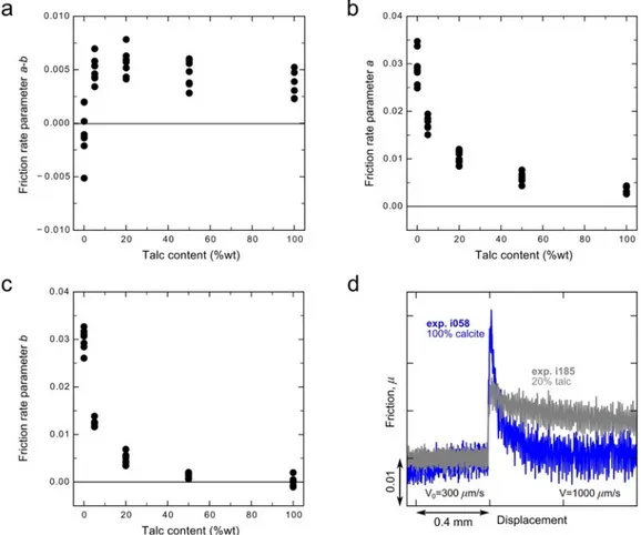
0.0061), and then remains almost constant. The friction rate parameter a, as well as the friction rate parameter b, decreases with increasing talc content (Figure 1.4b and c). The major drop in a and b is recorded between 0 and 20% of talc. The b value then remains close to zero with some negative values for the velocity steps 30-100 µm/s, 100-300 µm/s and 300-1000 µm/s in the pure talc sample. In Figure 1.4d we show a velocity step, 300-300-1000 µm/s, conducted on the pure calcite and on the 20% talc gouges: here we can observe the decrease in a values and the reduction of the b values to zero in response to an addition of 20% talc to pure calcite.
Figure 1.4. Friction rate parameters as function of talc content in experiments carried out at 5 MPa of normal
stress. a) Talc/calcite mixtures are characterized by velocity-strengthening frictional behavior, i.e. positive (a-b). b) The “direct effect” a decreases with increasing talc content. c) The “evolution effect” b decreases with increasing talc content approaching negative values. d) A comparison between the velocity dependence of 100% calcite gouge (blue) and 20% talc gouge (gray) at 5 MPa for a velocity step of 300-1000 µm/s.
1.3.1.2. Frictional behavior at 20 and 50 MPa normal stress
Mechanical results from the first suite of 14 experiments at 5 MPa highlight the presence of a threshold value corresponding to a talc content of 20%. In the calcite/talc series, most of the degradation in friction, healing rate and a and b parameters occurs by 20% talc. Moreover, our slide-hold-slide experiments showed that a content of 5% talc is enough to halve the
healing rate of calcite gouge. In order to better constrain the frictional properties of 5 and 20% talc gouges, we performed 4 additional experiments at higher normal stresses (i.e. 20 or 50 MPa).
The coefficient of friction of the 5% talc sample is systematically reduced with increasing normal stress (Figure 1.5): the 5% talc sample at 5MPa has µpeak ≈ 0.59 and µss ≈ 0.55,
whereas at 50 MPa has µpeak ≈ 0.50 and µss ≈ 0.49. The coefficient of friction of the 20% talc
gouge shows a strong reduction in the difference between peak friction and steady-state friction with increasing normal stress. The peak friction of the 20% talc sample systematically decreases from µpeak ≈ 0.49 at 5 MPa to µpeak ≈ 0.40 at 50 MPa (Figure 1.5a), whereas the
steady-state friction increases from µss ≈ 0.33 at 5 MPa to µss ≈ 0.36 (Figure 1.5b).
Figure 1.5. Peak friction (a) and steady-state (b) friction of talc/calcite binary mixtures as a function of normal
stress at talc contents of 5 and 20%. Experiments were carried out at a sliding velocity of 10 µm/s.
In Figure 1.6a we show healing values of 5 and 20% talc samples at different normal stresses versus hold time. Gouges with 5% talc show remarkably different healing values, Δµ, at higher normal stresses: the rate of frictional healing decreases with increasing normal stress ranging from β ≈ 0.0196 at 5MPa to β ≈ 0.0032 at 50 MPa. In Figure 1.6b, we report the different healing behavior of a 5% talc gouge at different normal stresses during a 3000 s hold: at 5 MPa Δµ ≈ 0.07267, whereas at 20 MPa Δµ ≈ 0.01473. The higher normal stress seems to suppress healing. Conversely, in sample with 20% talc, healing has no normal stress dependence: healing rate is almost constant with β ≈ 0.0021 at 5 MPa and β ≈ 0.0018 at both 20 and 50 MPa.
(a-b) values, ranging from 0.0042 to 0.0107. Moreover, at 50 MPa normal stresses, (a-b) systematically decreases with increasing velocity, whereas friction rate parameters a and b systematic increase with increasing velocity. In 5% talc sample, the friction rate parameter a (Figure 1.7b) slightly decreases with increasing normal stress, ranging from 0.0151 < a < 0.0194 to 0.0082 < a < 0.0133. In 20% talc sample, the reduction in a with increasing normal stress is less evident.
Figure 1.6. a) Frictional healing as function of hold time, talc content (5% and 20% talc) and normal stresses (5
MPa, 20 MPa and 50 MPa) in experiments carried out at a sliding velocity of 10 µm/s. Frictional healing of the 5% talc sample is strongly affected by changes in normal stress. b) Comparison between the healing of 5% talc gouge at 5 MPa normal stress (blue) and at 20 MPa normal stress (gray) in a 3000 s hold.
The parameter b (Figure 1.7c) shows a decrease between 5 and 20 MPa for both 5 and 20% talc gouges, whereas the b values at 50 MPa are more variable, becoming negative in some velocity steps (b ≈ -0.0025 for 5% talc in velocity step 1-3 µm/s, b ≈ -0.0019 for 20% talc in velocity step 1-3 µm/s). In Figure 1.7d we show two velocity steps conducted on the 5% talc gouge at different normal stresses: at 5MPa velocity-dependent behavior is characterized by
positive a and positive b in both velocity steps 1-3 µm/s and 100-300 µm/s, whereas at 50MPa velocity-dependent behavior shows different b parameter values, changing from negative b in velocity step 1-3 µm/s to positive b in velocity step 100-300 µm/s.
Figure 1.7. Friction rate parameters as function of normal stress (5 MPa, 20 MPa and 50 MPa) and talc content
(5% and 20%). a) Talc/calcite mixtures are characterized by velocity-strengthening frictional behavior, i.e. positive (a-b). b) The “direct effect” a decreases with increasing normal stress. c) The “evolution effect” b decreases with increasing normal stress approaching negative values. d) Comparison between the velocity dependence of 5% talc gouge at 5 MPa normal stress (blue) and at 50 MPa normal stress (gray) for velocity steps of 100-300 µm/s and 1-3 µm/s.
1.3.2. Microstructural observations
SEM investigations on the experimental faults at low normal stress, i.e. 5 MPa, indicate that deformation-induced microstructures are strongly controlled by the amount of talc. The texture of pure calcite sample (Figure 1.8a) is dominated by angular grains, isotropically distributed in a finer matrix. Overall, the structure is characterized by limited portions of
fine-observe limited fracturing and chipping (e.g., Billi, 2010) of larger calcite grains. The starting calcite grain size distribution shows a high concentration of fine material (50% of the volume is characterized by a grain size < 16 µm; Figure S1), which is clearly displayed in thin sections taken from samples after only the application of normal stress (Figure S2). We suggest that, in our saturated samples and at low normal stress, the deformation occurs via cataclastic flow, with grain rotation, translation and frictional sliding at grain contacts, with the development of few areas of fine-grained calcite. These discontinuous zones can develop from the portions of the starting material characterized by small grain sizes and do not testify a predominant role of grain size reduction during deformation.
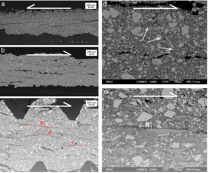
Figure 1.8. SEM micrograph showing microstructures developed in samples with variable talc content. (a)
Distributed deformation characterizes the pure calcite sample, γ ≈ 7.1. (b) The 5% talc sample deformed predominantly by cataclastic flow, γ ≈ 10.5. (c) The 20% talc sample localizes deformation along shear zones, with the YPR fabric described by Logan et al. (1992). The shear strain is γ ≈ 7.4. (d) Detail of the 5% talc sample showing talc lamellae iso-orientation (white arrows). (e) Detail of the 20% talc sample showing R1 shear zone
localized on talc lamellae.
In the 5% talc sample (Figure 1.8b and d), the texture is still homogeneous and dominated by a minor amount of large calcite grains (grain size > 100 µm). Calcite grains are more
rounded in comparison to the pure calcite gouge, suggesting a grain size reduction process such as chipping (Billi, 2010). Talc lamellae are scattered in the bulk microstructure, partially coating calcite grains and iso-orienting themselves forming a sort of “proto-foliation” (Figure 1.8d).
The microstructure of the 20% talc sample (Figure 1.8c and e) suggests a mixed mode of deformation with distributed deformation along the bulk microstructure and localization occurring along shear planes, defined on the basis of their geometric relationship to the YPR fabric described by Logan et al. (1992). Talc flakes scattered in the bulk microstructure are organized into foliation and are occasionally deformed by kinking and folding. R1 shear
planes show an enrichment of talc flakes and fine-grained calcite. The development of an interconnected network of talc lamellae around fine-grained calcite enables focusing of strain along shear planes. R1 shear planes (Figure 1.8e), ~10°-clockwise oriented to the shear plane,
are characterized by a high concentration of talc lamellae and the surrounding calcite grains display internal brittle deformation enhanced by the high strain condition. The continuity of R1 planes is high, whereas Y planes, parallel to the shear plane, tend to be more
discontinuous. Talc lamellae alignments can also be observed also along P foliation planes, ~145°-clockwise to the shear plane.
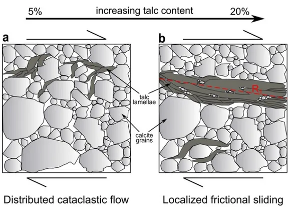
Our microstructural analysis shows that increasing talc content results in a progressive microstructural organization. The mechanism of deformation evolves from distributed cataclastic flow (0-5% of talc) to localized frictional sliding along talc-rich R1 shear planes
(20% of talc) with some grain size reduction and redistribution of finer calcite grains along shear planes, to distributed frictional sliding along talc-rich domains (50% of talc).
1.4. Discussion
1.4.1 Integration of mechanical data and microstructures
Peak and steady-state frictional strength decrease at two different rates (Figure 1.2). For both, a talc content of 20% is the value that marks a significant change in the degradation rate: a more rapid decrease at talc contents between 0%-20% is followed by a slower decrease from 20% to 100%. A talc content of 20% also strongly influences frictional healing (Figure 1.3) and velocity dependence (Figure 1.4). One possible explanation for this weakening trend is the generation of overpressure resulting from the decreasing permeability of gouges with increasing talc content. However, this mechanism unlikely provides a strong contribution to the weakening of our talc-bearing gouges, for mainly two reasons: our experiments were conducted under drained conditions, which allow the dissipation of any generated overpressure at least over the experiment time span, and the addition of only 5% of talc, which results in a decrease in friction, unlikely affects permeability parallel to the gouge such that overpressure would develop. Ruling out fluid overpressure as a weakening mechanism, on the grounds of microstructural observations we indicate the occurrence of shear localization on talc-enriched planes as the mechanism able to explain the variation in the frictional properties with increasing talc content.
Figure 1.9. a) A stress-supporting framework of calcite grains, with talc lamellae (5% wt.) situated between
some calcite grains, characterized by distributed deformation and resulting in high frictional strength, high frictional healing and high rate parameters. b) As the talc fraction increases, the development of interconnected talc network localizes deformation on planes (e.g., R1) and reduces the frictional strength, the frictional healing
At low talc concentrations (0-10%), the absence of continuous gouge portions characterized by a concentration of small calcite grains suggests no localization of grain-size reduction nor grain-size redistribution along shear bands. The overall lower amount of 100 µm-sized calcite grains and their more rounded shape in the 5 and 10% talc samples, when compared to the pure calcite gouge, can be interpreted as an enhanced grain size reduction due to the incipient development of talc foliation. The progressive alignment of talc lamellae is favored in regions where calcite grain size is reduced, progressively localizing the strain. However, in our low talc concentration gouges, this mechanism seems to not have a predominant role as demonstrated by a limited number of intragrain fractures within calcite grains. In addition, short and discontinuous alignments of talc (Figures 1.8b and d) indicate that the amount of talc is not enough to localize the shear. On the basis of all these observations, we can infer that distributed cataclastic flow is the main deformation mechanism (Figure 1.9a). These gouges are relatively strong, with µss ranging between 0.66
and 0.51 at 5 MPa, and the frictional healing is relatively high, with a healing rate β ranging between 0.036 and 0.012. The friction rate parameter a is high, with values ranging between 0.035 and 0.015. The direct effect a results from a change in gouge strength upon a velocity step, firstly attributed to a rate-dependence of contact strength (e.g., Dieterich, 1979). However, any porosity change in response to a velocity step influences gouge strength and consequently the a value. Moreover, different mechanisms, such as pressure solution and plasticity at grain contacts, can indirectly contribute to a values, influencing the properties of grain contacts and the porosity of our gouges. Dilatancy effects in gouge layers due to a step change in sliding velocity have long been recognized (e.g., Marone et al., 1990; Sammis and Steacy, 1994; Mair and Marone, 1999). Dilation of gouges rich in calcite, resulting from the rearrangement of the microstructure in response to a step to higher sliding velocity, consists in grains sliding and rotation and involves an increase in friction due to work expended against the normal stress. In our mixtures, calcite dilation influences the mixture behavior during slide-hold-slide experiments (Figure S4): the dilation of the 5% and the 20% talc samples are reduced, respectively, of about 40% and 60%, when compared with the pure calcite sample. The high dilation values associated with high healing values upon re-shear suggests a possible contribution of dilation, related to granular calcite, in the evolution of the a values with increasing talc. Nonetheless, time dependent mechanisms, such as pressure solution and plasticity at contacts can contribute to the direct effect. Pressure solution, strengthening at grain contacts, correlates positively with a values. Conversely, plasticity limits dilation
calcite gouges (Carpenter et al., 2016a), plasticity in calcite gouges, at room temperature, is an effective mechanism only at low slip velocities and high normal stresses, excluding an important contribution of plasticity in our low stress dataset. Furthermore, the large friction rate parameter b in calcite-rich gouges can be explained by the attainment of a new steady-state porosity following the microstructure rearrangement through granular dilation.
The 20% talc sample shows an YPR geometry (Logan et al., 1992) of the experimental gouge layer (e.g., Figure 1.8c) with talc lamellae concentrated along R1 shear planes. This
microstructure favors a deformation mechanism characterized by frictional sliding along the talc foliae (Figure 1.9b), typically observed in pure talc shear experiments (e.g., Boutareaud et al., 2012; Misra et al., 2014), promoting a decrease in the frictional strength to values of µss
ranging between 0.33 and 0.20. Similarly, Moore and Lockner (2011) in quartz/talc mixtures observed a marked weakening resulting from the formation of R1 planes that cross the entire
sample. Moreover, Hirauchi et al. (2013), shearing a mixture of antigorite and quartz at different experimental conditions generating different amounts of metasomatically grown talc, observed a weakening of the gouge associated with the progressive development of talc along through-going boundary shears. The almost zero healing of the gouges, with β smaller than 0.002, suggests that during hold periods the growing contact area, if it occurs, does not result in an increase in frictional strength. Talc lamellae, with their platy shape, can hinder growth of contact area. Following this interpretation, our data are in agreement with previous studies on phyllosilicates-rich fault rocks that have suggested real contact areas saturation in the actively slipping zone, due to crystal habit, as mechanism for inhibiting frictional healing (e.g., Bos and Spiers, 2001; Saffer and Marone, 2003; Tesei et al., 2012). The localization of deformation along interconnected, talc-rich shear surfaces coincides with the onset of a strong velocity-strengthening behavior, as previously observed in phyllosilicate-bearing gouges that developed a strong foliation (e.g., Bos and Spiers, 2002; Niemeijer and Spiers, 2005; Niemeijer and Spiers, 2006). In these previous works, the strong foliation allowed the attainment of a steady-state microstructure that does not require dilation upon a step to higher shearing velocity. Similarly, the development of connected, talc-rich shear surfaces where deformation is highly localized does not require any significant rearrangement upon a sudden change in velocity, favoring velocity-strengthening behavior. Specifically, the friction rate parameters a and b decrease with increasing talc content (Figure 1.4b and c): again a 20% talc content marks the larger change in the evolution of the rate parameters. We suggest that, by adding more and more talc along the experimental fault, cataclastic flow of granular calcite is overcome by frictional sliding along the platy talc, resulting in a less pronounced dilatancy