ACKNOWLEDGEMENT
At first place, I am thankful to almighty Allah who bestowed me with health, courage and strength to pursue this research, along with countless other blessings.
I greatly acknowledge the generous financial support from The Education, Audiovisual and Culture Executive Agency – EACEA/European Commission within the “Erasmus Mundus Doctorate in Membrane Engineering – EUDIME” (ERASMUS MUNDUS Program 2009-2013, FPA n. 2011-0014, SGA n. 2011-1599) for pursuing the current study.
I would like to express my deepest gratitude to Prof. Enrico Dioli, Dr. Pierre Aimar and Dr. Vlastimil Fila not only for supervising my research but also for making the practical arrangements to host my visits to their laboratories. I am also thankful to Dr. Francesca Macedonio for her technical support and valuable advice during my research.
I would like to extend my gratitude to current director of ITM-CNR Dr. Ledietta Giorno for providing me an excellent research environment during my stay at University of Calabria. I would also like to acknowledge the valuable cooperation from Prof. Molinari, Dr. Efrem and the other technical and administrative staff throughout my PhD.
I am also thankful to all my friends and colleagues from University of Calabria, University of Paul Sabatier Toulouse and Institute of Chemical Technology Prague for their multi-aspect provision. All the good moments that we spent together will always occupy a fraction of my mind in the form of golden memories. It is hard to move ahead without mentioning the support from Cejna, Fitim, Alessio Fuoco and Han Lee. The last three are specially acknowledged for their useless efforts to improve my football and basketball skills.
Last but not the least, I would like to express my sincere gratitude to all my family members for their encouragement, support and prayers that have been with me throughout my life.
Abstract
The current PhD work emphasizes on various aspects of membrane distillation for approaching zero liquid discharge in seawater desalination. In broader sense, two themes have been discussed in detail: (i) correlation between membrane features and their performance in MD (ii) understanding and control of thermal polarization in MD. Introduction and state-of-the-art studies of MD including progress in membrane development, understanding the transport phenomenon, recent developments in module fabrication, fouling and related phenomenon and innovative applications have been discussed in introductory part of the thesis. The effect of operating conditions and dope compositions on membrane characteristics and correlation between membrane features and their performance has been discussed in subsequent section. It has been established that membrane morphology plays a crucial role in performance of the membrane for real applications. Furthermore, it has been demonstrated that the effect of membrane morphology is different for direct contact and vacuum configurations.
Theoretical and experimental aspects of thermal polarization in direct contact membrane distillation have also been investigated. Thermal polarization phenomenon in a flat sheet membrane has been studied by using a specifically designed cell. The effect of operating conditions and solution concentration on thermal polarization has been explored experimentally. It has been observed that increased solution concentration favors the thermal polarization due to resulting poor hydrodynamic at the membrane surface and increase in diffusion resistance to the water vapors migrating from bulk feed phase to the membrane surface. Some active and passive techniques to decrease thermal polarization and possible fouling in membrane distillation have also been discussed in the current study. Thermal polarization can be greatly reduced by inducing secondary flows in the fluid flowing inside the fiber. The induction of secondary flows in the current study has been realized by using the fibers twisted in helical and wavy configurations. Due to improvement of thermal polarization coefficient on up and downstream, the undulating fiber geometries provide high flux and superior performance ratio. Application of intermittent and pulsatile flow to control thermal polarization in MD has also been discussed. It has been inferred that these flows have positive impact on performance ratio and volume based enhancement factors without compromising on packing density of the system. The application of MD for treatment of produced water has also been studied. The effect of membrane features on their performance for the treatment of this complex solution has been discussed. The desirable membrane features for successful application of MD for such treatment have been distinguished. It has been inferred that MD possesses the capability to produce a distillate of excellent quality and is an interesting candidate to recover the minerals present in the produced water. The fouling tendency of the membranes with different characteristics towards different types of feed solutions has also been discussed in this study. It has been shown that the porosity enhanced through the introduction of macrovoids in non-solvent induced phase separation technique creates problems
related with wetting and pore scaling during practical application of such membranes. The fouling related issues are less severe in the membranes with sponge like microstructure but the overall porosity of such membranes is relatively less. Thus it has been concluded that there should be an optimum between the high throughput and stable performance of the membranes synthesized through phase inversion techniques. Conclusions of the study and future perspectives have been discussed in the last section of the study.
Table of Contents
CHAPTER 1:
Introduction ... 1
1. Membrane operations and modern process industry ... 1
2. Membrane Distillation ... 4
2.1 Main challenges for MD ... 6
2.1.1 Inappropriate membranes ... 6
2.1.2. Thermal polarization ... 6
2.1.3 Nontraditional fouling ... 7
2.1.4 Loss of membrane hydrophobicity ... 7
2.1.5 Large scale applications ... 7
3. Thesis statement ... 7
References ... 9
CHAPTER 2: Membrane Distillation-an overview ... 11
1. MD configurations ... 11
2. Membranes for MD ... 12
3. Process understanding and modeling ... 17
4. Module designing for MD ... 19
5. Fouling in MD ... 22
6. Innovative and large scale applications ... 26
7. Recent commercial activities ... 29
References ... 33
CHAPTER 3: Membranes for membrane distillation ... 43
1. Introduction ... 43
2. Experimental ... 45
2.1. Hollow fiber preparation ... 45
2.2. Hollow fiber post treatment ... 45
2.3. Hollow fiber modules ... 46
2.4. Scanning electron microscopy (SEM) characterization ... 46
2.5. Mechanical properties ... 46
2.6. Bubble point and pore size distribution ... 46
2.7. Porosity measurement ... 47
2.8. Trans-membrane flux ... 47
2.8.2 Direct contact membrane distillation ... 49
2.9. Commercial hollow fiber membranes ... 49
3. Results and discussion ... 49
3.1. Membrane morphology ... 49
3.2. Mechanical properties ... 51
3.3. Porosity ... 52
3.4. Bubble point and pore size distribution ... 53
3.5. Membrane distillation ... 53
3.5.1 VMD results ... 53
3.5.2 DCMD results ... 54
3.5.3 Comparison between VMD and DCMD ... 57
3.5.4. Comparison of VMD performance with literature data ... 58
4. Conclusions ... 60
References ... 60
CHAPTER 4: Experimental and theoretical evaluation of temperature polarization
coefficient in direct contact membrane distillation ... 63
1. Introduction ... 63
2. Theory ... 64
3. Experimental ... 67
4. Results and discussion ... 69
4.1 Effect of hydrodynamic conditions ... 69
4.2 Effect of feed inlet temperature ... 75
4.3 Effect of feed concentration ... 79
5. Conclusions ... 84
Nomenclature ... 84
References ... 85
CHAPTER 5:
Active and passive techniques for controlling thermal polarization in
membrane distillation ... 87
1. Introduction ... 87
2. Mathematical background and modelling ... 89
3. Parametric analysis ... 96
4. Experimental ... 99
4.1 Membrane applied ... 99
4.3 Induction of intermittent and pulsating flow ... 99
4.4 MD tests ... 100
5. Results and discussion ... 101
5.1 Helical modules ... 101
5.2 Wavy and helical fibers ... 103
5.3 Intermittent and pulsatile flow ... 104
5.4 Performance ratio analysis ... 105
5.5 Packing density ... 107
6. Conclusions ... 108
References ... 108
CHAPTER 6: Membrane based processes for treatment of produced water: application
of MD ... 112
1. Introduction ... 112
2. Membrane based treatments for produced water ... 113
2.1 Pressure driven membrane processes ... 114
2.2 Electrochemical processes ... 114
2.3 Non-pressure driven membrane based processes ... 115
2.3.1 Forward osmosis ... 115
2.3.2 Membrane distillation ... 115
3. Experimental ... 118
3.1 Basic characterization ... 118
3.2 Membrane used ... 118
3.3 MD experimentation ... 118
3.3.1 MD set-up description ... 119
4. Results and discussion ... 120
4.1 Basic characterization ... 120
4.2 MD tests ... 121
5. Membrane crystallization of produced water ... 133
6. Conclusions ... 138
References ... 139
CHAPTER 7: Fouling in membrane distillation ... 141
1. Introduction ... 141
2.2. Effect of physical properties of solution ... 144
3. Membrane distillation experimentation ... 146
3.1 Reverse osmosis brine as feed ... 146
3.2 MBR effluent as feed ... 148
3.3 Produced water as feed ... 150
3.3.1 Intermittent operation ... 150
3.3.2 Effect of membrane washing ... 154
3.4 Whey solution as feed ... 155
4. Critical flux in MD ... 157
4.1 Proposed protocol ... 159
4.2 Kinetics ... 159
4.3 Factors affecting CF in MD ... 160
4.3.1 Feed temperature ... 160
4.3.2 Thermal polarization ... 161
4.3.3 Feed flow rate ... 161
4.3.4 MD configuration ... 161
4.3.5 Feed characteristics ... 161
4.3.6 Feed tank ... 161
5. Conclusions ... 162
References ... 162
CHAPTER 8: Conclusions and perspectives ... 163
Publications ... 165
Journal articles ... 165
Conference presentations ... 165
List of figures
Figure 1.1: Separation ranges for various membrane processes ... 2
Figure 1.2: Integrated membrane systems for desalination proposed in MEDINA project ... 4
Figure 1.3: Schematic of basic MD process ... 5
Figure 1.4: Illustration of heat transfer and thermal polarization in MD process ... 6
Figure 2.1: (a) Conventional MD configurations (b) Module arrangement for PGMD (c)
Schematic illustration of streams in V-MEMD module. ... 11
Figure 2.2: (a) A schematic diagram of the electrospinning process (b) SEM image of
electrospun membranes ... 16
Figure 2.3: MD mechanism for the membranes containing CNTs in their matrix ... 17
Figure 2.4: Space filled channels used to improve the hydrodynamic conditions at the
membrane surface in MD ... 20
Figure 2.5: Cascade module design used by He et al. ... 21
Figure 2.6: Various hollow fiber configurations used by Yang et al ... 22
Figure 2.7: Conceptual mechanism of hollow and heat recovery fibers reported by Singh and
Sirkar ... 22
Figure 2.8: Scale formation observed at the membrane surfaces and in distribution channels 24
Figure 2.9: Fouling caused by skim milk (top) and whey solution (bottom) as function of time
... 26
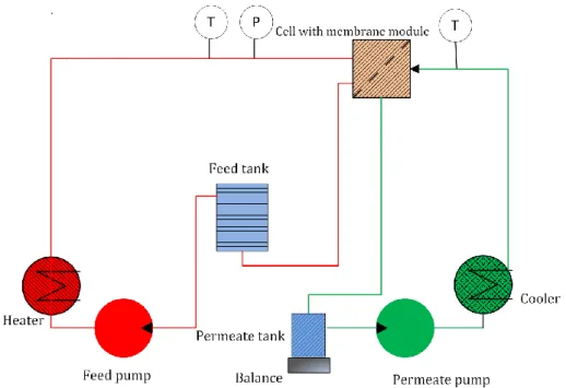
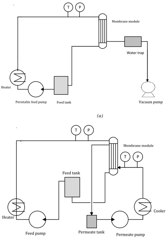
Figure 3.1: a) VMD set-up and b) DCMD set-up used in this work. ... 48
Figure 3.2: SEM pictures of fibers M1 ... 50
Figure 3.3: SEM pictures of fibers M2. ... 51
Figure 3.4: SEM pictures of fibers M3 ... 51
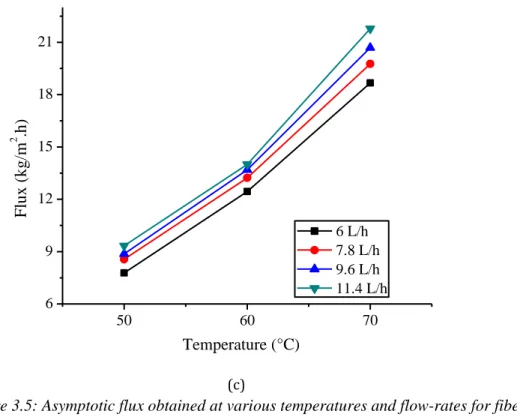
Figure 3.5: Asymptotic flux obtained at various temperatures and flow-rates for fibers type (a)
M1, (b) M2, (c) M3 ... 56
Figure 3.6: Average asymptotic flux obtained for various types of fibers at different
temperatures ... 57
Figure 3.7: Comparison of flux obtained at the same feed conditions (50°C, 6 L/h) for
different types of membranes used in DCMD and VMD tests ... 58
Figure 3.8: Comparison of VMD fluxs of fibers produced in this work and in [3]. Fibers
morphologies are highlighted ... 59
Figure 4.1: (a) Insight of the cell. (b) Front view of the cell (c) side view of the cell (d)
geometrical features of one half of the cell ... 68
Figure 4.2: Set-up used in the experimentation ... 69
Figure 4.3: Flux and feed side boundary layer resistance as function of Re ... 70
Figure 4.4: Theoretical and experimental temperature polarization coefficient as function of
Re ... 73
Figure 4.5: Effect of Reynolds number on thermal efficiency and heat transfer coefficient ... 74
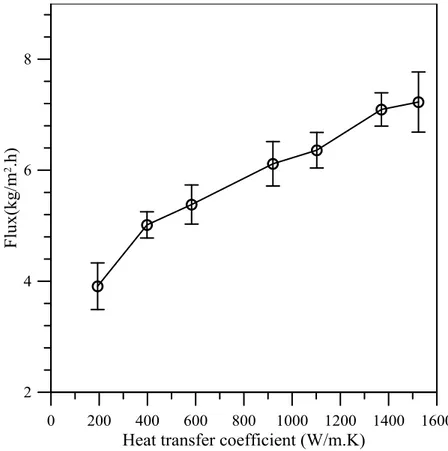
Figure 4.6: Dependence of trans-membrane flux on heat transfer coefficient of feed side ... 74
Figure 4.7: Effect of feed inlet temperature on trans-membrane flux. ... 76
Figure 4.8: Total heat flux, Reynolds number and temperature polarization coefficient as
function of feed inlet temperatures ... 77
Figure 4.9: Total heat transfer flux (Q), convective heat transfer flux (Q
v) and thermal
efficiency as function of feed inlet temperature ... 78
Figure 4.10: The effect of feed solution concentration on trans-membrane flux observed at
different feed inlet temperatures ... 80
Figure 4.11: Flux calculated on the basis of different considerations and the effect of feed
solution concentration and temperature polarization on reduction in flux. ... 81
Figure 4.12: Change in feed solution concentration and the corresponding Re with
experimental time ... 82
Figure 4.13: Dependence of heat transfer coefficient and Re on feed solution concentration . 83
Figure 4.14: Temperature gradient between bulk and membrane surface on feed side as
function of feed solution concentration at different temperatures ... 83
Figure 5.1: A tube helically wrapped around a rod ... 90
Figure 5.2: Nusselt number as function of Re for straight fibers (SF) and coiled fibers (CF)
according to different correlations ... 92
Figure 5.3: Algorithm used to calculate T
pmfor a known T
fm... 93
Figure 5.4: Re required to achieve a particular membrane surface temperature at feed side ... 94
Figure 5.5: Variation of flux with heat transfer coefficient ... 95
Figure 5.6: Heat transfer coefficient as function of Re according to different correlations ... 95
Figure 5.7: Resistance analysis as function of heat transfer coefficient ... 96
Figure 5.8: Effect of Re on heat transfer coefficient according to various correlations... 97
Figure 5.9: Effect of coil diameter on feed side heat transfer coefficient at Re=444 and pitch
of 4mm ... 98
Figure 5.10: The effect of pitch on Nusselts number inside the membrane at Re of 444 and
coil diameter of 16 mm ... 98
Figure 5.11: Schematic diagram of the helical module prepared in the lab ... 99
Figure 5.12: Simple procedure of inducing intermittent flow through a peristaltic pump and
flow pattern created ... 100
Figure 5.13: A simple arrangement applied to create pulsating flow ... 100
Figure 5.14: Comparison of flux observed for the module with straight fiber (SF) and coiled
fibers (CF) ... 101
Figure 5.15: Flux achieved for straight (FS) and helical coiled (FC) modules with whey
solution as feed ... 103
Figure 5.16: Normalized flux for wavy (WF) and helical fibers (HF) as function of feed side
Re ... 104
Figure 5.17: Flux for intermittent (IF), pulsatile (PF) and steady flow (SF) under the same
thermal conditions ... 105
Figure 5.18: Performance ratio for helical (HM), wavy (WM) and straight fiber (SM) modules
as function of feed side Re ... 106
Figure 5.19: Comparison of PR for steady, intermittent and pulsatile flows ... 106
Figure 5.20: Packing density (PD), area based enhancement factor (ABEF) and volume based
enhancement factor (VBEF) for different configurations and flow patterns ... 108
Figure 6.1: Main sources of produced water ... 113
Figure 6.3: A comparison of desalination technologies on the basis of energy consumption,
feed concentration and maximum achievable salinity level ... 116
Figure 6.4: Principles of nucleation theory ... 117
Figure 6.5: Schematic diagram of the set-up used for membrane distillation. ... 119
Figure 6.6: (a) Chromatograph and (b) Mass spectrum confirming the existence of
1,2-diethoxy ethane in the water. ... 121
Figure 6.7: Flux obtained by using PP1 based hollow fiber membrane. ... 122
Figure 6.8: Trans-membrane flux obtained by using lab-made PVDF1 based hollow fiber
membrane. ... 123
Figure 6.9: Flux obtained by using fiber type PVDF2 ... 123
Figure 6.10: Effect of feed temperature on flux for different membranes ... 125
Figure 6.11: Effect of feed flow rates on flux ... 126
Figure 6.12: Flux obtained at different feed inlet temperatures for feed flow rate of 50L/h . 127
Figure 6.13: Trans-membrane flux obtained at different feed flow rates for feed inlet
temperature of 50
oC ... 128
Figure 6.14: Flux obtained by using ceramic membranes. SW1 and SW2 indicate the flux
obtained with new membranes and washed membranes after wetting, respectively ... 130
Figure 6.15: Flux obtained for PP1, PVDF1 and PVDF2 membranes after 8 weeks of storage
... 131
Figure 6.16: Comparison of flux for two cycles of data for different membranes tested ... 131
Figure 6.17: Flux obtained by using PVDF2 membranes for 7hours of operation ... 132
Figure 6.18. Crystal size distribution (CSD) achieved during crystallization of produced water
(a) PVDF2, (b) PP1-Tfeed: 49°C, (c) PP1-Tfeed: 59°C. ... 135
Figure 6.19. Sodium chloride precipitated from produced water. ... 136
Figure 6.20. Length to width ratio of the obtained crystals. ... 137
Figure 6.21: SEM images of the crystals precipitated from produced water (a) Area of crystal
sample – magnification: 100x, (b) Single crystal – magnification: 5000x ... 137
Figure 6.22: Example of EDX spectra obtained for the crystals precipitated from produced
water. ... 138
Figure 7.1: Possible resistances to solvent transport encountered in low pressure membrane
processes ... 141
Figure 7.2: Parameters limiting the flux in MD under given process conditions ... 142
Figure 7.3: Schematic of dry and wet pore in MD (left and right respectively) ... 143
Figure 7.4: Effect of concentration on density and viscosity of solution ... 145
Figure 7.5: Effect of solution concentration on Pr and Re ... 146
Figure 7.6: Schematic diagram of membrane distillation set-up used ... 147
Figure 7.7: Flux as function of concentration for M3 and PP membranes ... 148
Figure 7.8: Flux obtained for MBR effluent as function of time by using PP membrane ... 149
Figure 7.9: Flux obtained for MBR effluent as function of time by using M3 membrane .... 150
Figure 7.10: Flux as function of time for M3 membrane for produced water as feed ... 151
Figure 7.11: Effect of wetted pore length on various resistances to mass transfer ... 152
Figure 7.12: SEM images of scaling present at surface of M3 at different magnifications ... 152
Figure 7.13: Flux as function of time for PP commercial membranes for produced water as
Figure 7.14: SEM picture of fiber type M3 ... 154
Figure 7.15: Flux for produced water during crystallization and the corresponding
concentration along with pure water flux before and after crystallization. ... 154
Figure 7.16: Flux and concentration achieved for straight and helical modules with inside-out
configuration ... 156
Figure 7.17: Flux achieved for straight fiber modified and unmodified modules with
outside-in configuration ... 157
Figure 7.18: Parameters defining the windows for critical flux at a fixed level of thermal
polarization ... 158
List of tables
Table 1.1: An overview of various membrane operations ... 2
Table 2.1: Advantages and disadvantages of the four main MD configurations. ... 12
Table 2.2: Characteristic features of some state-of-the-art UF membranes mentioned in
literature ... 14
Table 2.3: Some features of the commercial membranes used for MD ... 15
Table 2.4: Different types of fouling observed in MD studies ... 25
Table 2.5: Applications of MD mentioned in different recent studies ... 28
Table 2.6: Main companies involved in commercialization efforts for MD ... 29
Table 2.7: Recent patents in MD ... 31
Table 3.1: Glass Transition temperature Tg of polymers ... 44
Table 3.2: The compositions and operating conditions applied in spinning experiments ... 46
Table 3.3: Properties of the PVDF hollow fibers produced in this work and commercial PP
membrane used ... 52
Table 3.4: Results of the VMD tests performed using double distilled water as feed (Pvacuum
40 mbar, Tfin 50°C, Qfeed 6 L/h). ... 54
Table 4.1: Heat transfer correlations used in the literature for laminar flow ... 66
Table 4.2: Feed side boundary layer resistance and membrane resistance to the mass transfer
measured experimentally and calculated on the basis of different models ... 71
Table 4.3: Experimental and theoretical flux for various values of τ by using Knudsen
diffusion model, molecular diffusion model and the combined Knudsen and molecular
diffusion model ... 72
Table 4.4: Experimental and theoretical feed side heat transfer coefficients calculated for
various hydrodynamic conditions ... 75
Table 4.5: Resistance to mass transfer offered by feed side boundary layer at various feed
inlet temperatures ... 76
Table 4.6: Theoretical and experimental heat transfer coefficients for feed side ... 78
Table 4.7: Feed side membrane surface temperatures calculated by using heat transfer
coefficients given in Table 4.6 ... 79
Table 5.1 : A brief analysis of possible hydraulic techniques for fouling and thermal
polarization reduction in MD ... 88
Table 5.2: Parameters used for the calculation and module fabrication ... 91
Table 5.3: Heat transfer correlations for helical channels ... 92
Table 6.1: Some basic characteristics of the membrane applied in the study ... 118
Table 6.2: Some basic characteristics of the sample ... 120
Table 6.3: Properties of the permeate obtained ... 122
Table 6.4: Properties of permeate obtained by using Mycrodyn-Nadir PP based module .... 129
Table 6.5: Properties of distillate collected by using ceramic membranes ... 130
Table 6.6: Properties of the permeate obtained during reproducibility assessment tests ... 132
Table 6.7: Properties of the permeate obtained after 7 hours of continuous operation ... 132
Table 6.8: Comparison of some of the techniques used to treat produced water ... 133
Table 6.9: Cationic composition of produced water ... 134
Table 6.11: Crystal characteristics achieved in the crystallization of produced water ... 136
Table 7.1: Composition of synthetic brine ... 147
Table 7.2: Properties of permeate from reverse osmosis brine ... 148
Table 7.3: Properties of MBR effluent feed and distillate ... 149
CHAPTER 1
Introduction
1. Membrane operations and modern process industry
Separation, concentration and purification of molecular mixtures are the key requirements in process industry, underlying the importance of efficient separation in this sector. The state-of-the-art norms to achieve these objectives include distillation, extraction, crystallization, adsorption and ion exchange technology. These technologies are energy intensive in nature and generally mark a large footprint. For instance, it has been estimated that 60-70% of the energy requirement in petrochemical industry is anticipated in particular field of separation and purification. Thus the basic characteristics features of the conventional separation processes are contradictory to the basis of process intensification strategy [1]. Consequently, improvement or replacement of traditional separation techniques can offer a substantial impact on the process feasibility.
Contrary to the practice of the conventional process industry, depleting resources of energy and raw materials combined with environmental issues emphasize on sustainable industrial growth across the globe. The sustainable growth can be realized by using the material and energy resources more efficiently and rationally while at the same time, eliminating or minimizing the hazards associated with processes. Modern membrane engineering represents one of the possible and the most interesting way for developing processes in accordance with the guidelines provided by process intensification strategy to meet the challenges of the modern world [2]. Membrane engineering appears as a powerful discipline with characteristic features of efficient molecular separation, compatibility between different membrane operations in integrated systems to achieve the specific separation requirements, easy control and scale-up, chemical transformation and mass and energy transfer between different phases to realize the objectives of process intensification strategy.
Membrane engineering, at present, is providing interesting solutions to some of the major problems of our modern industrialized society for decreasing energy consumption, resolving environmental concerns and exploring the potential of many processes in a better and improved way. For instance, in many regions in the world conventional thermal desalination plants have been replaced with membrane process due to their 10-fold more energy efficient nature than thermal options; conventional activated sludge plants have been turned into membrane bioreactors due to their compactness (up to 5 times more compact than conventional plants), reduced sludge production and considerable level of physical disinfection [3]. In food industry, the membrane operations are availing interesting opportunities of concentrating the products and treating the wastewater streams. The use of membrane technology in energy production sector has opened the innovative gateways to produce electricity by using the concept of blue energy and fuel cells.
In addition to the conventional traditional pressure driven membrane processes, numerous new membrane operations have emerged recently with significant potential in various area. The new operations differ from the conventional ones mainly in terms of driving force and/or separation mechanism. The driving force for majority of the conventional membrane operations including microfiltration (MF), ultrafiltration (UF), nanofiltration (NF) and reverse osmosis (RO) is the pressure gradient. The processes such as electrodilaysis (ED), electrodilaysis reversal (EDR) and electrodeionization are driven by the electrochemical potential whereas temperature gradient is the
driving force for the membrane distillation (MD) and membrane dryers. The separation ranges for the conventional pressure driven processes have been provided in Figure 1.1 while a summary of the driving forces, mode of separation and permeating and retaining species for conventional and some new processes has been provided in Table 1.1. Size exclusion is the main governing separation mechanism for conventional pressure driven processes, however, chemical nature of the species also plays an important role in NF and RO.
Figure 1.1: Separation ranges for various membrane processes Table 1.1: An overview of various membrane operations
Process Driving Force Mode of
transport Species Passed Species Retained
Microfiltration (MF) Pressure difference 100 - 500 kpa Size exclusion convection Solvent (water) and dissolved solutes Suspended solids, fine particulates, some colloids Ultrafiltration (UF) Pressure difference 100 - 800 kpa Size exclusion convection Solvent (water) and low molecular weight solutes (<1000 da) Macrosolutes and colloids Nanofiltration (NF) Pressure difference 0.3 - 3 mpa Size exclusion solution diffusion Donnan exclusion Solvent (water), low molecular, weight solutes, monovalent ions Molecular weight compounds > 200 da multivalent ions Reverse osmosis (RO) Pressure difference 1 - 10 mpa Solution diffution mechanism
Solvent (water) Dissolved and suspended solids
Gas Separation (GS) Pressure difference 0.1 – 10 mpa Solution diffusion mechanism Gas molecules having low molecular weight or high solubility-diffusivity
Gas molecules having high molecular weight
or low solubility-diffusivity Pervaporation (PV) Chemical potential or concentration difference Solution diffusion mechanism High permeable solute or solvents
Less permeable solute or solvents
Electrodialysis (ED)
Electrical potential difference,1 – 2 v / cell pair
Donnan exclusion Solutes (ions) small quantity of solvent Non-ionic and macromolecular species Dialysis
(D) Concentration difference Diffusion
Solute (ions and low mw organics) small solvent
quantity
Dissolved and suspended solids with
mw > 1000 da Membrane contactors (MC) Chemical potential, concentration difference; temperature difference Diffusion Compounds soluble in the extraction solvent; volatiles Compounds non soluble in the extraction solvent; non volatiles Membrane based solvent extraction (MBSX) Chemical potential or concentration difference Diffusion partition Compounds soluble in the extraction solvent Compounds non soluble in the extraction solvent Membrane distillation (MD)
Temperature difference Diffusion Volatiles Non volatiles Supported
liquid membranes
(SLM)
Concentration difference Diffusion
Ions, low MW
organics
Ions, less permeable organics Membrane
reactors (MR)
Various Various Permeable
product
Non permeable reagents Membrane
crystallization Temperature difference Diffusion Volatiles Non volatiles Forward
osmosis Osmotic gradient
Solution
diffusion Solvent
Dissolved and suspended solids Membrane
emulsification Pressure gradient Convection Dispersed phase Membrane
dryers Vapor pressure gradient Diffusion Volatile Non volatiles
In many parts of the world, the dependence on seawater for industrial, drinking and household purposes has greatly increased. Conventionally, seawater desalination is carried out through state-of-the-art pressure driven membrane based processes due to their significant advantages compared to
addressed, operation at high pressure and disposal of brine being the most significant obstacles that negatively affect the process economy and cause environmental problems. New membrane based operations offer promising solutions to desalination problems. The use of new processes in integration with the traditional ones can not only resolve the problem of waste handling but also provides the opportunity to boost the overall recovery factor and economy of the process. Integrated approach takes into account energy saving, water rationalization, minimization of resource utilization and waste production [4]. Therefore, integrated systems can contribute significantly to the solution of strategic aspects of industrial productions. Different membrane operations can be coupled in integrated systems for approaching the ambitious objective of “zero liquid discharge”. For instance, in seawater desalination conventional pressure driven membrane operations can be combined with other innovative membrane processes such as membrane distillation (MD) or membrane crystallization (MCr) for achieving the aspiring objective of reaching very high recovery factor (around 85-90%) [5] (Figure 1.2).
Figure 1.2: Integrated membrane systems for desalination proposed in MEDINA project [5] 2. Membrane Distillation
Membrane distillation (MD) is one of the innovative membrane based processes that was documented for the first time in 1963 [6]. However, only recently, it gained significant popularity among the scientific and engineering community. Different terminologies have been used for the process till the ‘‘Workshop on Membrane Distillation’’ held in Rom during May, 1986. The definition of MD was confined in the workshop to the process utilizing the hydrophobic, porous membrane with the pores allowing the transport of vapors without capillary condensation. It was also acclimatized that membranes must not alter the vapor liquid equilibrium, at least one side of the membrane must be in contact with liquid feed and the necessary driving force is provided by vapor pressure gradient across the membrane. The process finds promising applications in various areas of membrane engineering including water desalination, treatment of industrial effluent, pharmaceutical industry, food industry, removal of organic compounds from aqueous streams and in a number of other applications. The process is based on temperature gradient created across a microporous membrane that separates vapor-liquid phases in equilibrium as illustrated in Figure 1.3 and therefore the process performance is relatively insensitive to the feed concentration. The hydrophobic nature of the membranes ensures the passage of only vapor phase through the membrane. The process possesses some unique advantages in comparison to conventional distillation or pressure driven membrane based processes: theoretically
possibility to use waste grade heat or energy, less stringent requirements in terms of mechanical strength of membranes and possibility to concentrate the solutions to their saturation level [7].
MD has the capability to replace reverse osmosis process if cheap or low grade waste energy is available [8]. Substantial potential of practical application of MD in processes such as water desalination exists in the areas with relatively hot climate. In Middle East, half of the domestic oil consumption is associated with water purification every year. MD can play a crucial role in decreasing this proportion significantly due to the abundant solar energy available in Middle East. However, it is worthy to note that in most of the cases, MD should be considered as an optimum compromise between its energy intensive nature and healthy impact on environment.
MD can be easily adapted to other systems. It can be coupled with the solar energy systems to utilize the low grade energy; it can be used separately or in integration with other processes such as membrane bioreactors (MBRs), forward osmosis (FO), microfiltration (MF), ultrafiltration (UF), nanofiltration (NF) and RO to improve the efficiency of the process in terms of purity and recovery factor. In case of seawater desalination, MBR and UF/MF can improve the pre-treatment whereas MD can be used to recover the water from the residual brine. Moreover, the use of MD as membrane crystallization unit allows to extract not only further water but also the minerals contained in the brine streams (e.g., sodium, chlorine, magnesium, sulphate, calcium, potassium, bicarbonate, and eventually also lithium, bromine, and many more) [9][10]. MD based processes, such as membrane crystallization and osmotic membrane distillation, have opened innovative gateway to obtain the crystals from salt solutions and to concentrate various solutions to the limits which are not achievable through conventional pressure driven processes. Another interesting application of MD is its potential to recover toxic or/and useful compounds and heavy metals from various sorts of industrial effluents which can be reused in the process or can be separated from the effluent to avoid their adverse environmental impact [11][12]. Hence, MD can provide an innovative, cost effective and easy-to-adopt pathway with significant impact in terms of benefits obtained to achieve the goals of green chemistry.
2.1 Main challenges for MD 2.1.1 Inappropriate membranes
The unavailability of the membranes specifically designed for MD is the biggest obstacle for widespread applications of MD. Traditionally, the membranes prepared for ultrafiltration and microfiltration through phase inversion processes have been utilized for MD applications. These membranes generally have low porosity, limited hydrophobicity, broader pore size distribution and pore size not engineered for MD requirements. The thickness of these membranes has been design to withstand relatively high pressure of UF and MF which is not encountered in MD. Accordingly, MD flux for such membranes is low and at the same time conductive losses are high.
2.1.2. Thermal polarization
Thermal losses associated with the thermal polarization (also referred as temperature polarization) is another issue that suppresses the process performance. In direct contact membrane distillation (DCMD), a hot feed and a cold permeate are in direct contact with the opposite sides of the membrane. The transport of heat across the membrane takes place through conduction and transport of the hot vapors through the membrane (Figure 1.4). Consequently, the temperatures at the membrane surfaces are different from their values in the bulk. Temperature or thermal polarization coefficient is used to describe the thermal efficiency of the process. It is defined as the ratio of the difference of feed and distillate temperatures at membrane surfaces to the corresponding difference in the bulk.
fm pm f p T T TPC T T
The value of temperature polarization coefficient approaching to unity describes a thermally efficient process. In poorly designed system, significant heat is lost due to thermal polarization.
2.1.3 Nontraditional fouling
Due to different transport phenomenon and operating mechanism, generally rigorous feed characteristics and use of hydrophobic membranes, the nature of fouling in MD is different from other low pressure membrane processes. Scale formation at membrane surface is the most common form of fouling observed in MD process when applied to concentrated salt solutions. Wetting of pores has the similar effect as that of the fouling in conventional pressure driven membrane operations. With the advent of novel applications of MD, other types of fouling can also be seen in various studies. For example, the fouling phenomenon becomes more significant and sever while treating the solutions rich in organic contents [13] [14]. The thickness of the fouling layer can play a decisive role in controlling the heat and mass transfer across the membrane [15].
2.1.4 Loss of membrane hydrophobicity
MD process essentially relies on the hydrophobic nature of the membranes to retain the liquid on one side of the membrane while allowing the passage of only vapors. The intrusion of liquid inside the membrane pores is referred to as pore wetting. The successful application of the membrane distillation has been associated with the fulfilment of non-wettability criteria of membrane pores. When the hydraulic pressure exceeds the liquid entry pressure, the membranes are prone to wetting. The effect of wetting is not only possible reduction in flux and degradation of permeate quality but also a severe fouling inside the pores caused by the precipitated/adsorbed materials. Certain components from aggressive feed solutions can interact with the membrane material to alter its hydrophobic nature. Similarly, low surface additives present in the feed can penetrate through the pores and can damage the hydrophobic character of the pores. Biofouling can also play a role in decreasing the hydrophobicity of the membranes.
2.1.5 Large scale applications
Traditionally, MD has been utilized for desalination purposes as an alternative to RO or to overcome limited recovery of RO and other thermal desalination techniques [16]. Moreover, MD has been considered as a viable candidate in arid areas which lie in the region with abundant solar energy available, thus further confining its application mostly for desalination [17]. However, a lot of other interesting applications of MD have been explored due to less fouling tendency of the process, the potential to treat the complex feed solutions and due to the fact that the separation is driven by the temperature induced phase equilibrium establish at a particular temperature. The temperature gradient base nature of the process also opens new novel opportunities to use it for vapor/gas separation applications where the equilibrium composition at any temperature is enriched with the more volatile component. Consequently, the sphere of applications of the process has extended beyond the traditional use of desalination. However, most of these studies have been carried out at lab scale and require more pilot scale studies to bridge the gap between lab scale testing and commercial scale application.
3. Thesis statement
The aim of this thesis is to further enhance the understanding of fundamental identified constraints of MD, specifically thermal polarization and membrane characteristics required for MD. The qualitative application of the conclusions drawn is believed to be applicable for practical applications of MD, though the carried out research and mentioned results are based on laboratory work. A brief overview of each chapter included into the thesis has been described below.
A general overview of state-of-the-art of MD has been provided in chapter 2. The chapter elaborates different conventional and emerging configurations of MD, recent trends in membrane synthesis and module fabrication, new attempts to elaborate heat and mass transport mechanism in MD, fouling in MD and novel applications of the process.
There is a strong need to understand the correlation between membrane features including morphology, porosity, mean pore size, pore size distribution and their performance in MD. On one hand, it is well established that the membranes with high overall porosity and large pore size favor the mass transport of vapors from feed to the permeate side while on the other hand, the presence of large pores in the membrane can make the membranes more prone to wetting. Furthermore, it is not only the overall porosity that favors the high flux but the microstructure of the membrane also plays a key role in dictating the membrane performance. Chapter 3 describes the relationship between the membrane properties and their performance against different solutions. The lab made membranes have been tested in vacuum and direct contact configurations for different feed solutions and the relationships between the membrane characteristics and performance has been explored.
As stated previously, thermal polarization severely affect MD process in an environment characterized by poor hydrodynamic and high feed temperature. There are several correlations in the literature relating the hydrodynamic of the system with thermal polarization, yet still literature suffers from the lack of direct experimental realization of temperature polarization based on the experimentally measured temperatures at membrane surface. The experimental study of temperature polarization carried out by using a cell specifically designed for this purpose has been described in chapter 4. Various approaches have been used in the literature to minimize the temperature polarization in MD. Module designing and flow patterns can play a significant role in decreasing the thermal polarization in MD. Chapter 5 describes the effect of wavy and helical shaped fibers on temperature polarization on MD process. The effect of pulsatile and intermittent flow patterns has also been described in this chapter.
The sphere of potential applications of MD is growing rapidly. The process has been tested for the applications ranging from the separation of volatile aroma components to the recovery of organic and inorganic crystals from various solutions. One growing field of potential interest is the oil and gas industry. With exhausting oil reserves and discovery of the non-conventional reservoirs of natural gas, the handling and treatment of produced water is becoming increasingly important. Produced water is characterized with the presence of very high salt content and small fractions of oil and greases. The treatment of such complex water is challenging for the conventional membranes based processes. MD is considered as an appropriate candidate for the treatment of this complex solution. Chapter 6 discusses the feasibility of MD process for the treatment of gas field produced water by using membranes with different characteristics. Initial studies to recover crystals from produced water have also been discussed in this chapter.
Fouling is a major operational problem in all pressure driven membrane processes. The nature of fouling in MD is different from traditional pressure driven processes. Nontraditional fouling in MD has been discussed in chapter 7. MD has been operated on various feed solutions including whey solution, MBR effluent from a hospital industry, RO brine and produced water to study the fouling tendency of various membranes. The possible concept of critical flux in MD has also been described in this chapter.
The main conclusions of the work and future directions have been highlighted in chapter 8. The potential directions for the membrane preparation, fouling and temperature polarization control have been discussed in this chapter.
References
[1] A. I. Stankiewicz and J. A. Moulijn, “Process Intensification: Transforming Chemical Engineering,” Chem. Eng. Prog., no. January, pp. 22–34, 2000.
[2] E. Drioli, A. Brunetti, D. Pro, and G. Barbieri, “Process intensi fi cation strategies and membrane engineering,” Green Chem., vol. 14, pp. 1561–1572, 2012.
[3] E. Drioli, A. I. Stankiewicz, and F. Macedonio, “Membrane engineering in process intensification — An overview,” J. Memb. Sci., vol. 380, pp. 1–8, 2011.
[4] E. Drioli, E. Curcio, G. Di Profio, F. Macedonio, and a. Criscuoli, “Integrating Membrane Contactors Technology and Pressure-Driven Membrane Operations for Seawater
Desalination,” Chem. Eng. Res. Des., vol. 84, no. 3, pp. 209–220, Mar. 2006.
[5] E. Drioli, A. Criscuoli, and F. Macedonio, Membrane Based Desalination: An Integrated Approach (MEDINA). IWA Publishing, 2010.
[6] B. R. Budel, “Silicone Rubber Vapor Diffusionin Saline Water Distillation,” US Patent 285,032,1963.
[7] M. Khayet, “Membranes and theoretical modeling of membrane distillation : A review,” Adv. Colloid Interface Sci., vol. 164, no. 1–2, pp. 56–88, 2011.
[8] S. Alobaidani, E. Curcio, F. Macedonio, G. Diprofio, H. Alhinai, and E. Drioli, “Potential of membrane distillation in seawater desalination: Thermal efficiency, sensitivity study and cost estimation,” J. Memb. Sci., vol. 323, no. 1, pp. 85–98, Oct. 2008.
[9] F. Macedonio, C. A. Quist-jensen, O. Al-harbi, H. Alromaih, S. A. Al-jlil, F. Al Shabouna, and E. Drioli, “Thermodynamic modeling of brine and its use in membrane crystallizer,”
Desalination, vol. 323, pp. 83–92, 2013.
[10] C. M. Tun and A. M. Groth, “Sustainable integrated membrane contactor process for water reclamation , sodium sulfate salt and energy recovery from industrial ef fl uent,” Dsalination, vol. 283, pp. 187–192, 2011.
[11] A. El-abbassi, A. Ha, M. Khayet, and M. C. García-payo, “Integrated direct contact membrane distillation for olive mill wastewater treatment,” Desalination, vol. 323, pp. 31–38, 2013. [12] E. Drioli, E. Curcio, A. Criscuoli, and G. Di, “Integrated system for recovery of CaCO 3 , NaCl
and MgSO 4 · 7H 2 O from nanofiltration retentate,” J. Memb. Sci., vol. 239, pp. 27–38, 2004. [13] S. Goh, J. Zhang, Y. Liu, and A. G. Fane, “Fouling and wetting in membrane distillation ( MD ) and MD-bioreactor ( MDBR ) for wastewater reclamation,” DES, vol. 323, pp. 39–47, 2013. [14] A. Hausmann, P. Sanciolo, T. Vasiljevic, M. Weeks, K. Schroën, S. Gray, and M. Duke,
“Fouling mechanisms of dairy streams during membrane distillation,” J. Memb. Sci., vol. 441, pp. 102–111, 2013.
[15] Z. Ding, L. Liu, J. Yu, R. Ma, and Z. Yang, “Concentrating the extract of traditional Chinese medicine by direct contact membrane distillation,” J. Memb. Sci., vol. 310, no. 1–2, pp. 539– 549, Mar. 2008.
[16] S. Adham, A. Hussain, J. M. Matar, R. Dores, and A. Janson, “Application of Membrane Distillation for desalting brines from thermal desalination plants,” Desalination, vol. 314, pp. 101–108, 2013.
[17] M. Rasool and F. Banat, “Desalination by solar powered membrane distillation systems,” Desalination, vol. 308, pp. 186–197, 2013.
CHAPTER 2
Membrane Distillation-an overview
Recently, numerous studies have been carries out with the aim to develop the appropriate membranes for MD, to improve the process understanding, appropriate module fabrication and to confirm the feasibility of the process for several applications. In order to improve the process efficiency, some new configurations have also been investigated. An overview of recent state-of-the-art developments in various aspects of MD has been provided in current chapter.
1. MD configurations
Depending on the methods to induce vapor pressure gradient across the membrane and to collect the transported vapors from the permeate side, MD processes can be classified into four basic configurations (Figure 2.1a). A common feature of all the configurations is the direct exposure of one side of the membrane to the feed solution used. DCMD has been the most studied mode due to its inherent simplicity [1]. On the other hand, vacuum membrane distillation (VMD) can be used for high output while air gap membrane distillation (AGMD) and sweep gas membrane distillation (SGMD) enjoy the benefit of low energy losses and high performance ratio [2][3][4]. Some new configurations with improved energy efficiency, better permeation flux or smaller foot print have been proposed such as material gap membrane distillation (MGMD) [5], multi effect membrane distillation (MEMD) [6], vacuum-multi effect membrane distillation (V-MEMD) [7] and permeate gap membrane distillation (PGMD) shown in Figure 2.1b [8]. A pros and cons analysis of conventional configurations has been provided in Table 2.1.
Figure 2.1: (a) Conventional MD configurations (b) Module arrangement for PGMD [9] (c) Schematic illustration of streams in V-MEMD module [7].
(b)
Table 2.1: Advantages and disadvantages of the four main MD configurations.
Configuration Pros Cons
DCMD
The easiest and simplest configuration to realize practically, flux is more stable than VMD for the feeds with fouling tendency, high gained output ratio [2], it might be the most appropriate configuration for removal of volatile components [4].
Flux obtained is relatively lower than vacuum configurations under the identical thermal conditions, thermal polarization is highest among all the configurations, flux is relatively more sensitive to feed concentration, the permeate quality is sensitive to membrane wetting, suitable mainly for aqueous solutions.
VMD
High flux, can be used for recovery of aroma compounds and related substances, the permeate quality is stable despite of some wetting; no possibility of wetting from distillate side, thermal polarization is very low.
Higher probability of pore wetting, higher fouling, minimum selectivity of volatile components [4], require vacuum pump and external condenser.
AGMD
Relatively high flux than SGMD, low thermal losses, no wetting on permeate side, less fouling tendency.
Air gap provides an additional resistance to vapors, difficult module designing, difficult to model due to the involvement of too many variables, lowest gained output ratio[2].
SGMD
Thermal polarization is lower, no wetting from permeate side, permeate quality independent of membrane wetting.
Additional complexity due to the extra equipment involved, heat recovery is difficult, low flux, pretreatment of sweep gas might be needed.
Recently, Memsys have applied a patented concept of integrating vacuum with multi effects in their module designing for MD. V-MEMD is a modified form of VMD that integrates the concept of state-of-the-art multi effect distillation into the VMD. As a general principle of the process, the vapors produced in each stage are condensed during the subsequent stage. Vapors are generated in steam raiser working under vacuum by exchanging the heat provided by external source. The vapors are condensed by exchanging the heat with feed separated with a foil. The vapors generated in 1st stage are transported through the membrane and collected on the foil in the 2nd stage. The flow of different streams in a single stage has been illustrated in Figure 2.1c. It has been claimed that these modules has excellent gained to output ratio which is crucial parameter for industrial applications [7]. A condenser is used to condense the vapors generated in final stage. The vapor pressure in each stage is less than its preceding stage.
2. Membranes for MD
As briefly discussed in Chapter 1, traditionally the membranes prepared for low pressure membranes processes have been utilized for MD applications. There are several aspects of these membranes that need further improvement for successful application in MD. For example, the thickness of the conventional membranes for MD has been designed for MF/UF requirements. While considering such membranes for MD, on one side, low thickness offers less resistance to the mass transfer, while on the other hand,
membranes with low thickness suffer from more energy losses due to heat flux flowing through conduction across the membranes [10]. In order to address the thickness issue, dual and even triple layer membranes have been introduced [11]. These membranes contain a hydrophobic active layer and a hydrophilic support layer. The support layer provides thermal insulation and ensures the required mechanical robustness of the membrane while the active layer retains the liquid. Care must be taken in selection of thickness of the active layer as too less thickness can allow the passage of the liquid through the pores and may not be sufficient to resist the chemical attack from the feed side during long term operations. According to Laganà et al [12] optimum thickness of active layer is 30-60 um. However, a broad look at thickness effect on MD performance reveals that the literature lacks of clear and conclusive statements. For example, for concentrated salt solutions, Gosteli et al [13] have observed that the performance of thin membrane is more sensitivity towards concentration, however, no further investigations have addressed this issue. Wu et al [14] have demonstrated that the optimal thickness for electro spun PVDF based membrane increases with reduced heat transfer coefficient, decreased feed inlet temperature and increased permeability and salinity level. Contrary to this, Jansen et al [15] have found that conduction losses are directly related with the temperature gradient at the membranes surfaces and inversely related with the membranes thickness.
For what concerns pore size, the utilized porous membranes don't show a single pore size; rather they exhibit a range of pore size distribution (PSD). A membrane with good PSD shows a Guassian distribution curve with a sharp peak and very narrow width. As evident from Table 2.2, the membranes used for UF show quite a broad range of minimum and maximum pore sizes which is somehow acceptable for UF applications. On the other hand, both mean pore size and pore size distributions are crucial for MD process. Although higher flux has been reported for the membranes with bigger pores, yet the large pore dimensions make the membrane vulnerable to wetting. The presence of even a few oversized pores can kill the efficiency of the entire process by allowing the passage of liquid through the pores. Therefore, for pore size, an optimization is required between the stable performance and high flux [16]. The commonly used pore size for MD is in the range of 100 nm to 1um [17]. The sensitivity of process performance towards pore size is different for different configurations of MD. The hydrophobicity of the membrane material and surface tension of the feed solution used will play a decisive role in deciding the pore size. The presence of pores with different dimensions gives rise to the involvement of different mass transport mechanisms in a single membrane [18]. Regarding the membrane material, it has to be hydrophobic to ensure the retention of liquid and the passage of only vapor phase through the membrane pores. PVDF, PP and PTFE are the most commonly used polymeric materials used for membrane preparation for MD applications. Among these, PTFE exhibits the best hydrophobic characteristics, yet the most research on membrane preparation has been carried out by using PVDF membranes due to its easy processability. PTFE is not soluble in any solvents and therefore, poses serious issues with processing. In order to render/improve the hydrophobic character, various techniques have been applied including the coating of different low energy flouro polymers at the membrane surface [19], plasma modification [20], formation of various hierarchical structures [21], incorporation of nano particles into the dope solution during membrane synthesis [22], making the surface rough [23] etc. Surface roughness is an interesting technique to render the super hydrophobicity to the membrane surface; however, its further effects on surface scaling/fouling and thermal polarization still need to be addressed.
Table 2.2: Characteristic features of some state-of-the-art UF membranes mentioned in literature (For details of abbreviation used to describe the membranes, please consult the corresponding reference)
Membrane type rmin(nm) rmin(nm) rav(nm) 𝜀 (%) Ref.
XM 100A 5 12 9 0.75 [24] XM 300 6 19 12.5 0.3 [24] Milipre PTSG 1 15 3 7-12 [25] PVDF 3 4 - 10 [26] Polyimide UF 1.5 6 - 0.7-0.9 [27] PCTE 10 134 258 181 6 [28] PCTE 50 553 821 657 14 [28] PCTE 100 98 5 1233 113 3 45 [28] PTHK 16 8 33 6 22 1 34 [28] YM 6.3 18 11.3 - [29] PM30 16.7 62.7 30.6 - [29] GVHP - - 283.2 70.1 [16] PVHP - - 463.9 71.3 [16]
In addition to the above all parameters, membrane porosity plays a crucial role in dictating the flux. More porous membranes offer more diffusion surface for the vapors and at the same time decrease the thermal conductivity of the membrane as the air trapped inside the pores has conductivity 10 times less than typical polymeric materials used. Overall porosity also dictates the mechanical stability of the membrane. However, it must be highlighted that it is not only the overall porosity that is important for the successful application but also the mechanism of achieving the porosity. The membranes having macro voids usually show very good porosity or void fraction but on the other hand are more prone to the wetting [30]. Related to the porosity is the tortuosity of the pores which indicates the effective length that vapors have to travel to move from feed side to the permeate side. The commonly used value for tortuosity factor is close to 2, though some studies have taken the tortuosity factor as the inverse of porosity [16].
Properties of some commercial membranes used for MD applications have been provided in Table 2.3. Comparison of Table 2.2 and Table 2.3 indicates that the membranes properties required for two applications are very different. The second significant conclusion is that the required MD membrane properties have been incorporates to some extent in some commercial membranes (for example see the rav, rmin, rmax, and porosity for TF1000, TF450 ,TF200, GVHP), however, the optimization of these features, further ‘’engineering’’ of the membranes and additional improvement in module design can make them further attractive.
Table 2.3: Some features of the commercial membranes used for MD Membrane
type Manufacturer Material rmin (nm) rmax (nm) rav (nm) δ (µm) LEP (bar) 𝜀 (%) Ref. TF1000 Gelman PTFE/PP 280 420 325 178 282 80 [18], [127] TF450 Gelman PTFE/PP 180 300 235 178 138 80 TF200 Gelman PTFE/PP 120 210 155 178 48 80 PV22 Millipore PVDF - - 220 126 2.29 62 [128] PTS20 Gore PTFE/PP - - 200 184 4.63 44 PT45 Gore PTFE/PP - - 450 77 2.88 89 Accurel® S6/2 AkzoNobel PP - 600 200 450 1.4 70 [129] HVHP Millipore PVDF 280 680 451.23 105 33.64 [129] GVHP Millipore PVDF 200 350 265.53 204 32.74
MD080CO2N Enka Microdyn PP - - 200 650 70
[18]
Accurel® Enka A.G PP 600 400 74
Celgard X-20 Hoechst Celanese Co PP - 70 50 25 35
EHF270FA-16 Mitsubishi PE - - 100 55 70
Besides optimizing the features (pore size, pore size distribution, overall porosity etc.), some efforts have also been devoted to engineer the structure of membrane. Wang and Chang [31] have fabricated multi bore PVDF hollow fiber membranes by using especially designed spinneret. The membranes are claimed to have better mechanical strength and provide easy module fabrication. Edwie and Chung [32] have investigated the ‘‘layer effects’’ on performance of MD process. The authors have prepared and compared the performance of single layer PVDF membrane, dual layer hydrophilic/hydrophobic PVDF membrane and dual layer hydrophobic/hydrophilic PVDF/PAN membrane. The most stable performance was achieved by using the single layer membrane with small pore size having cellular morphology.
Thermal induced phase separation (TIPS) is another interesting technique to synthesize the membranes with narrow and controlled pore size distribution. Recently, some investigations have been performed to fabricate and analyze the performance of PP membranes prepared through TIPS. Tang et al [33] have prepared isotactic polypropylene based membranes with narrow pore size distribution by using TIPS. The factors affecting the structure and performance of these membranes were studied. The method seems to be very promising to fabricate the membranes with specific features for MD applications.
(a) (b)
Figure 2.2: (a) A schematic diagram of the electrospinning process [34] (b) SEM image of electrospun membranes [30]
Recent trends in membrane synthesis process for MD incorporate the use of innovative technologies such as nanotechnology having a significantly potential role in membrane based desalination techniques including MD. For instance, electrospun nano fiber membranes have been reported in many studies recently and have shown very interesting results. In electrospinning process, the fibers are spun under the pressure and electric field applied and form non-woven mat at the grounded rotating collectors (Figure 2.2). The mat formed shows very high porosity, excellent hydrophobicity, very good interconnectivity and very high surface to volume ratio making them interesting candidates for desalination applications. Eletrospinning can be performed with polymer solution or melt and the properties of the mat can be tuned by changing the process parameters, material used and the post treatment step applied [34][35][36]. Due to the possibility to use polymer melt, instead of solution, electrospinning provides opportunities to make the membranes with vast variety of polymers. Different functional materials can be incorporated into the nano fibers during or after their spinning thus incorporating multi functionality into the fibers. Some lab scale applications of electrospun nano fiber membranes have also been reported in recent literature [35][36] [37].
Graphene is an interesting material with several applications due to its very high strength to weight ratio. In addition to its use in various fields (foldable electronics, biological engineering, composite materials, energy storage), the new research has shown that it exhibits amazing selective permeability towards various components. For example, a sub-micron thin graphene oxide membrane can retain all gases and liquids except water molecules [38]. The separation of water from organic mixtures has been demonstrated excellently by these membranes [39]. Similarly, graphene membranes can selectively permeate some metals ions present into a solution containing different types of ions [40]. Graphene membrane with thickness about 1 nm has shown excellent selectivity towards various gases [41]. Due to these facts combined with their high strength, it is possible to tremendously reduce the thickness of the graphene based membranes that can open broad opportunities for these membranes in desalination applications including MD. The applications of graphene membranes in water treatment sections are being tested by different researchers [42], [43], [44].
Nanofibrousmat
Whipping instabilities Polymer solution ormelt
Biomimic membranes like aquaporin have shown a great potential for desalination applications due to their high permeability and selectivity towards water molecules. Under the right conditions, aquaporin membranes form the water channels allowing the passage of only water molecules and exclusion of all ions. It has been postulated that aquaporin based membranes can achieve a water flux as high as 601 Lm-2h-1bar-1 which is an order of magnitude higher than conventional RO process [45]. The commercial application of such membranes for water desalination is however still far away due to insufficient stability of the membranes, difficulties associated with commercial scale production and limited rejection of salts exhibited by the existing membranes [46].
The use of carbon nanotubes (CNTs) in water desalination is also emerging in lab scale investigations. CNTs comprise of rolled up cylinder of graphene with nano scale dimensions. Their exceptional mechanical strength, chemical resistance and thermal properties are well known. As illustrated in Figure 2.3, very high transport of water molecules inside the CNTs and their potential to change the water-membrane interaction to stop the permeation of liquid water molecules while favoring the preferential transport of vapors through the pores have encouraged their incorporation into the membrane matrix [47] [48]. On the other hand, for desalination through MD, CNTs based membranes provide excellent porosity and hydrophobicity. The initial studies to demonstrate the potential of CNTs membranes for desalination through MD have been provided in references [49] and [50]. The application of CNT based membranes in MD has caused considerable increase in flux enhancement for salt solution [48].
Figure 2.3: MD mechanism for the membranes containing CNTs in their matrix [47] 3. Process understanding and modeling
Numerous recent publications aim to address the understanding of heat and mass transport phenomenon in MD from different perspectives. Like past, the most of the studies are based on theoretical approaches. New

![Figure 1.2: Integrated membrane systems for desalination proposed in MEDINA project [5] 2](https://thumb-eu.123doks.com/thumbv2/123dokorg/2872437.9520/18.892.202.694.405.700/figure-integrated-membrane-systems-desalination-proposed-medina-project.webp)
![Figure 2.3: MD mechanism for the membranes containing CNTs in their matrix [47] 3. Process understanding and modeling](https://thumb-eu.123doks.com/thumbv2/123dokorg/2872437.9520/31.892.112.762.550.1004/figure-mechanism-membranes-containing-matrix-process-understanding-modeling.webp)
![Figure 2.6: Various hollow fiber configurations used by Yang et al [68]](https://thumb-eu.123doks.com/thumbv2/123dokorg/2872437.9520/36.892.212.683.261.482/figure-various-hollow-fiber-configurations-used-yang-et.webp)
![Figure 3.8: Comparison of VMD fluxes of fibers produced in this work and in [3]. Fibers morphologies are highlighted](https://thumb-eu.123doks.com/thumbv2/123dokorg/2872437.9520/73.893.129.808.393.815/figure-comparison-fluxes-fibers-produced-fibers-morphologies-highlighted.webp)