UNIVERSITÀ DI SIENA
Dipartimento di Biotecnologie, Chimica e Farmacia
Corso di dottorato in Scienze Chimiche e Farmaceutiche
XXXIII ciclo
Settore scientifico disciplinare: CHIM/03
Functionalization of Black Phosphorus with
Inorganic Reagents
Tutor: Dottorando:
Dr. Maurizio Peruzzini Matteo Vanni
Dr.ssa Maria Caporali
Prof. Stefano Mangani
Coordinatore:
Maurizio Taddei
Anno Accademico 2020/2021
MATTEO VANNI 15.02.2021 14:26:08 UTCABSTRACT
PhD candidate: Matteo Vanni
Tutor: Dr. Maurizio Peruzzini, Dr.ssa Maria Caporali, Prof. Stefano Mangani Dissertation: Functionalization of Black Phosphorus with Inorganic Reagents
____________________________________________________________________
Since its first reported exfoliation in 2014, the interest in black phosphorus has grown dramatically. The direct band gap, the high carrier mobility and the large specific surface area of BP open up great opportunities in different topical sectors of physics and chemistry including catalysis. As each phosphorus atom in BP has an sp3 hybridization and is bearing a lone-pair, an effective approach to surface modification could encompassthe coordination of transition metal fragments. In this thesis, the functionalization of exfoliated black phosphorus (2D BP) with different palladium precursors is presented. In particular, a new nanohybrid was obtained growing Pd NPs in situ on 2D BP. The new material, named Pd/BP, was characterized by means of different spectroscopic techniques and electron microscopy measurements. The existence of Pd‒P bonds of 2.26(3) Å between peripheral Pd atoms of the nanoparticles and BP flakes was revealed via EXAFS measurements, highlighting the ability of 2D BP to act as an effective ligand toward the surface of metal NPs. The nanohybrid Pd/BP was used successfully as heterogeneous catalyst in the liquid phase hydrogenation of chloronitrobenzene to chloroaniline, resulting extremely selective in the process. Remarkably, comparative studies carried out with Pd NPs supported on carbon as reference material, revealed that the use of BP as support is crucial to reach higher selectivity.
Following a distinct approach, the functionalization of 2D BP was accomplished by addition of the organometallic precursor [Pd(C3H5)Cl]2 to 2D BP. In-depth solid state characterization carried out by means
of powder XRD and solid state 31P CP-MAS NMR allowed to unravel the nature of the new material.
HAADF-STEM microscopy performed at atomic level was exploited to probe the morphology of the flakes, revealing the existence of a uniform distribution of the metal within 2D BP, with no formation of metal aggregates, such as Pd NPs. EXAFS measurements, together with DFT simulations, revealed the existence of unprecedented interlayer Pd‒Pd dimers, bridging two BP layers. Consistently with morphological and structural analysis, testing the material (named Pd2/BP) in the benchmark hydrogenation of C=C and C≡C bonds, the metal sites
resulted inaccessible to organic substrates. Conversely, preliminary studies on the application of Pd2/BP in the
hydrogen evolution reaction (HER) from acidic medium, pointed out a strong enhancement in electrocatalytic activity compared to pristine 2D BP.
Alla mia famiglia
e a Benedetta
Index
Chapter I
Introduction
1.1.
The 15
thelement
………. 1
1.1.1. Overview ..……… ……….. 1
1.1.2. White phosphorus ………... 1
1.1.3. Red phosphorus, violet phosphorus, and related
modifications ….……… 3
1.1.4. Black phosphorus……… 6
1.2.
Black phosphorus: physical properties,
exfoliation and characterization
……….. 10
1.2.1. Physical properties ………. 10
1.2.2. Exfoliation of BP: routes to 2D BP and BPQDs ……… 13
BP nanosheets (2D BP) .……….……... 13
BP quantum dots (BPQDs) ………... 21
1.2.3. Experimental characterization of exfoliated BP………. 22
1.3.
Environmental stability of 2D BP
.……… 27
1.3.1. BP degradation ………... 27
1.4.
Chemical functionalization of 2D BP
……….. 35
1.4.1. Overview ……… 35
1.4.2. Functionalization with metal nanoparticles ………... 36
Co/BP ……….. 36
Ni/BP ……….. 37
Pt/BP….………... 38
Ag/BP ………. 39
Au/BP ……….. 40
1.4.3. Non-covalent functionalization of 2D BP ………. 41
TCNQ-BP ………41
Anthraquinone-BP ………...42
Pyren-1-boronyc acid-BP ……… 43
1.4.4. Covalent functionalization of 2D BP ………. 44
Functionalization via arylating reagents………..……… 44
Functionalization with organic azides ……… 46
Functionalization with organic electrophiles ……….. 47
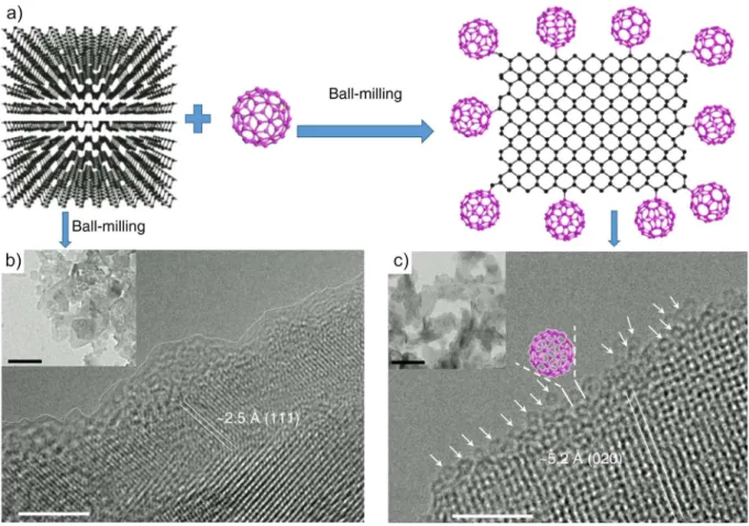
Functionalization with fullerene ………. 49
Functionalization with metal complexes………. 50
1.5.
List of abbreviations
………. 54
1.6.
Chapter I References
……… 55
Pd/BP nanohybrid: unravelling the nature of Pd‒P
interaction and application in selective
hydrogenation
2.1 Introduction
………... 65
2.2 Materials synthesis
………. 65
2.2.1 Preparation of 2D BP ……… 65
2.2.2 Preparation of Pd/BP ……… 66
2.3 Characterization and discussion
………... 67
2.4 Catalytic tests
………... 72
2.5 Conclusions
……….. 76
2.6 Appendix A
………... 77
2.7 Chapter II References
………... 83
Chapter III
Interlayer functionalization of black
phosphorus with Pd‒Pd dimers
3.1 Introduction
………... 85
3.2 Material synthesis
………... 86
3.2.1 Preparation of 2D BP ……… 86
3.2.2 Functionalization of BP with DIM……… 86
3.4 Catalytic activity
………. ……… 95
3.4.1 Hydrogenation of alkenes and alkynes ………. 95
3.4.2 Application in HER ………... 96
3.5 Conclusions
.………. 98
3.6 Appendix B
………... 100
3.7 Chapter III References
………. 115
1
Chapter I
Introduction
1.1 The 15
thElement
1.1.1 Overview
Phosphorus (symbol P) is a chemical element of the nitrogen group, with atomic number 15. Its name comes from ancient greek φόςφορος (light bearer), because of the faint glow emitted when the white allotrope is exposed to oxygen. Though not present on Earth as a free element, phosphorus is found inside minerals, such as phosphate rocks (containing the tetrahedral anion PO43-) and in living beings.
An adult human body contains an average of 0.7 Kg of phosphorus, mainly located in teeth and bones in the form of apatite. At a molecular level, phosphorus plays a crucial role in the architecture and in the metabolism of cells. Cytoplasmic membranes consist of a bilayer structure of phospholipids, whose orientation is imparted by the polarity of the phosphorus-containing heads. Phosphate groups are key components of both DNA and RNA frameworks, and noticeably, all forms of life base their intracellular energy transport on the molecular vector ATP (adenosine triphosphate). Notably, it was by urine, a biological source, that phosphorus was isolated for the first time in 1669 by Henning Brand, a German alchemist. Besides its crucial biological role, phosphorus is also extensively used in industry to prepare a plethora of compounds, including fertilizers, pesticides, plasticisers and flame retardants. In its elemental state, at ambient conditions, phosphorus can take different allotropic forms, among these, the only molecular compound is white phosphorus, made of discrete P4 molecules. The others, namely red,
violet and black phosphorus, are all polymeric solids with different structures. The next section will be dedicated to a survey of the distinct phosphorus allotropes, indulging a little bit on their fascinating story and structure determination
1.1.2 White phosphorus
White phosphorus (WP) is the most common and reactive form of the element and for this reason the most interesting from the industrial point of view. In pure form, it looks like a white and waxy solid, with a melting point of 44.1 °C and boiling point of 280 °C. WP reacts immediately with oxygen forming P4O10, a reaction highly exothermic that leads to self-ignition. For this reason, WP is usually stored
under a layer of water and is carefully handled always under inert atmosphere. Beside the risk related to flammability, this substance is also extremely toxic, causing severe liver damage if ingested or adsorbed
2
through the skin. When first isolated by H. Brand after a tedious and somewhat serendipitous process, phosphorus was obtained concentrating large quantities of urine to a paste, heating this residue at high temperature inside a retort and collecting the evolved vapours in water. What most likely happened during such process was the reduction of phosphate salts by organic compounds present in the mixture, yielding gaseous phosphorus that condensed as the white allotrope. White phosphorus is composed of tetrahedral P4 molecules of suggestive beauty, where the phosphorus atoms occupy the vertices of the
simplest platonic solid, as shown in Figure 1a. The presence of tetratomic molecules in the gas phase was guessed by early vapour density measurements, but their geometry was determined only in 1935 by L.R. Maxwell et al. [1] through electron diffraction studies of heated vapours. Today it is known that P4
is stable in the gas phase until 800 °C, when dissociation takes place with formation of P2 diatomic
molecules. Atomic distribution studies carried out in 1938 by S. Gingrich et al. [2] demonstrated the existence of P4 molecules also in the liquid state. Solid white phosphorus may exist in three different
modifications, named α-, β- and γ-P4. The solid phase obtained by condensation of the vapours is α-P4.
Early crystallographic investigations carried out on this phase suffered from the slow conversion to the red allotrope under light illumination or from the high degree of thermal disorder [3,4], which prevents any structure solution. The crystal lattice is likely body-centred cubic, with a complex structure featuring 58(1) molecules in the unit cell. If α-P4 is cooled down at ambient pressure, at −77.6 °C a reversible
transition to β-P4 takes place. An alternative approach to obtain β-P4 is to crystallize it from concentrated
solutions of α-P4 in CS2 below -77.6 °C. The β phase may be stabilized at room temperature under a
pressure of 10 Kbar. Single crystal determinations carried out on β-P4 by A. Simon et al. [5] revealed a
triclinic lattice (P-1) with 3 molecules in the asymmetric unit. The refined structure is shown Figure 1.
Figure 1. Molecular structure of P4 (left) and unit cell of β-P4 (right), generated from data by A. Simon [5]. Thermal ellipsoids
3
Finally, yet another low-temperature modification of white phosphorus was discovered in 1974 and named γ-P4 [6]. This form is monoclinic, with only two P4 molecules inside the unit cell mirroring each
other. γ-P4 can be prepared quenching α-P4 to – 165°C and keeping it at this temperature to enable the
α → γ transition. The tetrahedral geometry of P4, lacking a central atom as in the case of tetrahedral
carbon, is quite rare in chemistry. Other examples are As4, related mixed pnictogen compounds AnB4-n
(n= 1-3), as well as C4H4 (tetrahedrane) and B4Cl4 and some polyatomic anions belonging to the
bewilding family of Zintl ions [7]. In a simple valence bond description, each P atom is sp3 hybridized.
However, as the P−P−P angles measure ~ 60°, there is a strong distortion from the ideal value of 109.5°, making the P4 tetrahedron extremely strained and reactive. That is why WP is the industrially most
relevant allotrope of the element, with an annual production of about 910,000 tons. Today, WP is still produced by reduction of phosphates, although of inorganic origin (phosphorites). Phosphates ores, rich in fluorapatite, are mixed with silica and reduced with carbon at temperatures greater than 1100 °C in an arc-furnace, through a highly energy-consuming process. Silica is added in the form of gravel to lower the melting point in the slug. The overall reaction is the following:
2 Ca5F(PO4)3 + 9 SiO2 + 15 C → 9 CaSiO3 + CaF2 + 15 CO (g) + 3 P2(g)
On cooling down P2 gas dimerizes yielding P4. The off gas, mainly containing P4 and CO, is sent to a
condensation tower were WP is recovered under water. About 85% of P4 produced is burned to P2O5
and hydrated to make high purity phosphoric acid. The remaining 25% is mainly employed in the production of phosphorus-containing molecules that require the element as a reactant, such as PCl3,
POCl2, P2S5, NaH2PO2 and to a less extent red phosphorus.
1.1.3 Red Phosphorus, violet phosphorus and related modifications
Among the elements, the ease of phosphorus to form chains is matched only by that of carbon. Moving from discrete P4 tetrahedra to larger Px motifs and extended structures, this feature gives rise to a
tremendous structural variability. Since the discovery of white phosphorus, early investigators noticed that upon exposure to sun light the solid acquired a yellow colour. Sometimes, even a reddish coating formed on its surface. However, chemists of the time considered the red residue just a lower product of oxidation. It was only in 1850 that the existence of a red form as a distinct modification of elemental phosphorus was established by A. von Schrötter [8], who also managed to prepare red phosphorus (RP) heating the white allotrope at 280°C in inert gas. Unlike WP, RP is both thermodynamically and kinetically more stable at room temperature and does not react with oxygen if exposed to air. Indeed, ignition takes place only at 300°C. It is insoluble in most solvents due to its polymeric nature and contrary to the white allotrope, it is non-toxic. Thanks to this feature, the first application of RP after its discovery was in the manufacture of matches, replacing toxic WP used previously. Today, RP is principally used as flame retardant in plastic materials and in the production of some phosphorus containing materials such as semiconductors, pyrotechniques, fertilizers and pesticides. The actual
4
production is usually based on a batch process, in which white phosphorus is heated slightly above its boiling point for one-two days. During this time red phosphorus accumulates in the slurry, which gets more and more viscous over time. When solidification takes place (at about 70% of yield), conversion to the red allotrope is completed heating at higher temperatures. The material prepared heating the white allotrope is amorphous, but if specific thermal treatments are applied, different modifications of the red allotrope are accessible, with different degree of crystallinity but all reddish in colour. This variability created much confusion among early investigators. This is also the reason why WP was historically chosen as reference state for the element in thermodynamic calculations, despite being the less stable allotrope. In 1947, based on thermal analysis and XRD powder patterns, W.L. Roth assessed the existence of five distinct polymorphs of red phosphorus, of which two had crystalline character [9]. One of these crystalline modifications had been known since 1865, when it was prepared by J.W. Hittorf [10], and today is called violet phosphorus (VP) or Hittorf’s phosphorus. Hittorf’s synthetic method consisted in sealing amorphous red phosphorus inside an ampoule and heating at 550°C, growing violet phosphorus crystals by sublimation on the colder end of the ampoule. Violet phosphorus may also be prepared by recrystallization from solutions in molten lead or bismuth. The structure of this modification, shown in Figure 2, was solved in 1966 by Thurn and Krebs from single crystal data, resulting monoclinic and characterized by a complex architecture [11].
Figure 2. a) and (b) Structural models of Hittorf’s phosphorus reported by Thurn and Krebs [11].c) Ball and stick representation of VP structure with added yellow tubes to highlight the orientation of tubular channels inside the structure. Reproduced from reference [12].
The building blocks are tubular units with pentagonal cross section, that are arranged in layers. Double-layer structures are formed by vertical covalent linking of perpendicular tubular strings. Independent tubular units inside each layer, as well as distinct double-layer motifs, are held together by weak van der Waals interactions. The space group of the structure, originally assigned to P2/c by Thurn and Krebs, was recently corrected to P2/n (no.13) during a single crystal structural redetermination carried out by J. Zhang and coworkers [13]. Remarkably, the second crystalline modification of RP suggested by Roth back in 1947 was identified and fully characterized in 2005 by M. Ruck and coworkers [14]. Because
5
of its morphology, it was named fibrous phosphorus. This modification often crystallizes with the violet one. The structure is closely related to that of VP and the two have exactly the same density. They differ in the alignment of the linked phosphorus channels, which instead of being perpendicular run parallel to each other (see Figure 3a-b).
Figure 3. a) Arrangement of the double tubes along the fiber axis in fibrous phosphorus. b) Stacking of the layers in Hittorf's phosphorus. Reproduced from reference [14]. c) Structure of 1
∞[P12] phosphorus strands present in (CuI)8P12 and (d) (CuI)3P12. Reproduced from reference [15].
It should now be remarked that the discover of fibrous phosphorus by Ruck was anticipated by theoretical studies, carried out by Böcker and Häser, addressing the systematic investigations of plausible bonding pattern in phosphorus chains [15,16]. The structure of fibrous phosphorus, still unknown at the time of these investigations, was predicted to be a stable modification of the element, energetically equivalent to the violet allotrope. This report highlighted also how distinct structures, built out of similar units, closely related to the violet and fibrous ones, could display a comparable thermodynamic stability. Some examples of these architectures may be found in (CuI)8P12 or (CuI)3P12
[15], whose structures contain independent phosphorus chains, see Figure 3b-d. In 2004 A. Pfitzner [18] managed to isolate these units through a Cu-extraction method by cyanide complexation, washing crystal of the copper halide adduct with cyanide solutions. The isolated material consisted in
phosphorus nanorods with amorphous structure (likely caused by a difficult packaging of the phosphorus strands), in fact a new amorphous modification of the element. These findings, from theoretical investigations to experimental characterizations, helped to unravel the nature of common (amorphous) RP, which is probably made up of the same building units of violet and fibrous
phosphorus, but lacking an ordered structure. This conclusion is further strengthened by recent research on phosphorus nanostructures. Starting from ab initio calculations on the stability of ring-shaped chains (named r-P) [19,20], in 2017 J. Zhang and coworkers [21] succeeded growing ring-type structures inside multi-walled carbon nanotubes (MWCNTs) nanoreactors. Sealing red phosphorus and carbon nanotubes inside an evacuated ampoule, then heating at 500°C, phosphorus fragments slowly diffused inside the nanotubes and polymerized in ring shapes (see Figure 4f-g).
6
Figure 4. Polymerization of P4 molecules inside MWCNTs. a) and (b) HRTEM images of MWCNTs containing polymeric
phosphorus structures. c) Noise‐filtered HRTEM image of the region highlighted in (b). d) Simulated HRTEM image and (e) the corresponding atomic structure of a single zigzag P-chain inside MWCNT. Reproduced from reference. [22] f) HRTEM image of r‐P grown inside a MWCNT (named r-P@MWCNT). Rectangular inset: simulation of the r‐P@MWCNT based on the structural model in (g). Scale bar = 1 nm. h) Side view of r‐P. Reproduced from reference [21]
The cylindrical walls of the MWCNT acted as a template during the polymerization in rings and provided a stabilization to the growing structure. Similarly, M. Hart et al. [22,23] used single wall carbon nanotubes (SWCNTs), much thinner in diameter than MWCNs, to encapsulate P4 molecules, up to about
10 %wt. When lined up inside the nanotube, P4 tetrahedra polymerized forming different 1D structures.
Of these, the zig-zag ladder (see Figure 4d-e) is a structural motif that is present also in Hittorf’s and fibrous phosphorus architectures. Thus, these 1D structures could represent a snapshot of the very first stage in the transition from WP to RP. These last examples show how exciting this area of structural inorganic chemistry still is. Despite being started more than a century ago, new recent discoveries have been made that help to clarify old missing points.
1.1.4 Black phosphorus
Back in 1914 physicist and Nobel prize winner P. Bridgman, in an attempt to induce a transition from WP to RP under the influence of hydrostatic pressure, obtained unexpectedly a dark solid material. He recognized it as a new allotropic modification of the element and called this substance black phosphorus (BP) [24], being thermodynamically more stable than WP and RP and with higher density (2.691 g/cm3).
The new material looked crystalline and with fracture similar to that of graphite, however a structural characterization was not carried out. The preparation of BP from white phosphorus under Bridgman’s
7
conditions was not an easy task, requiring 1.2 GPa of pressure at 200°C, taking approximately 30 minutes. Later in 1935 R. Hultgren et al. [2], working on samples prepared by Bridgman himself, were able to determine the structure of BP from powder patterns, with the aid of radial distribution functions. As it turned out, BP is orthorhombic with space group Cmce (no. 64), and has a layered structure reminiscent of graphite, where each monolayer (named phosphorene) is made of P6 rings. However, in
graphite the C6 motif is planar, making the graphene monolayer flat meanwhile BP is formed by P6 unit
with a chair conformation, like a cyclohexane molecule. This makes the phosphorene layer puckered, with an alternation of ridges and valleys, enabling the distinction of two non-equivalent coplanar directions, an armchair direction (AC) and a zigzag direction (ZG) (see Figure 5b-c). Different perspectives of the structure of BP are reported in Figure 5. This structural divergence between phosphorene and graphene is easy to explain taking into account the different hybridization of the two elements, namely sp3 for phosphorus in BP and sp2 for carbon in graphite.
Figure 5. a) Detail of the BP structure with highlighted unit cell. b) Prospective view of a BP monolayer featuring the puckered arrangement of the phosphorus atoms and highlighting the two non-equivalent zigzag (red line) and armchair (blue line) directions. Different views of the structure along the b axis (c), the a axis (d) and the c axis (e) are also shown. Ellipsoids are drawn at 80% probability.
After the early studies by Bridgman, the first low pressure synthesis of BP was reported in 1955 [25] [26] and starting from equal amounts of WP and mercury, which were sealed inside an evacuated glass ampoule and heated at increasing temperatures from 280 to 380 °C, over a week. However, this method was strongly affected by the purification steps required to eliminate mercury impurities from BP. Improvements were made growing crystals of BP from WP solutions in molten bismuth, which provided needle-shaped crystals, easier to purify from Bi with nitric acid washings. This method allowed A. Brown and S. Rundqvist to obtain a sample of BP suitable for single crystal characterization [27]. Structure refinement by single crystal established that the model of Hultgren and coworkers was
8
substantially correct. Recrystallization from bismuth remained the method of choice for many decades, though it did not overcome the need of an easy, non-toxic and effective preparative route. This was fulfilled in 2007 by T. Nilges and coworkers [28], who reported a chemical vapour transport (CVT) route to grow large BP crystals from RP inside a sealed ampoule, heating the red allotrope for several days at 600°C in presence of AuSn alloy and SnI4 as mineralizing agent. Later, using a programmed
temperature with heating and cooling ramps, it was possible to reduce the reaction time at 33 h [29]. Beside the possibility of growing crystals more than 1 cm in diameter, the great value of this method was the remarkable quality and purity of the crystals obtained. Though traces of reagents and by-products were found on the surface of the BP crystals, they could be conveniently removed by mechanical separation without any further chemical purification step. The reacting mixture is complex, as many simultaneous equilibria are present at 600°C involving gaseous P4, molten Sn, SnI2, I2, in
addition to binary and ternary systems such as Sn4P3 and Au3SnP7. The latter was indicated as the
potential site for an epitactic growth of BP, based on structural similarities. A remarkable improvement of the synthesis, which still represents the state-of-the-art, came in 2014 [30]. This last optimization allowed to reject the use of expensive Au, saving costs and drastically reducing the number of byproducts. Following this procedure, only Sn and SnI4 are needed beside RP to prepare BP. The reagent
mixture is sealed in a quartz ampoule, which is heated at ~ 650 °C inside an oven, building up a temperature gradient of 45-50 °C along the ampoule. The bulk regents are located at the hotter end of the ampoule and products form by vapour transport at the colder one (see Figure 6).
Figure 6. Synthesis of bulk BP crystals from RP according to the CVT method reported by T. Nilges, based on the Sn/I couple. a) Representative silica glass ampoule after the synthesis of BP. SnI4 (orange) and red phosphorus (red) from the gas phase are
condensed at the right hand side of the ampoule. BP is formed in large bunches. Excessive Sn reacted to form SnxPy species,
which are present in small round spheres. Reproduced from reference [30]. b) Experimental setup of the CVT reaction, according to reference [31]. c1) Quartz ampoule as it looked at the end of the reaction, featuring large BP crystals (c2). Reproduced from reference [32]
9
Some debate still exists around the actual mechanism of BP growth. To gain insights on the role of the Sn/SnI4 additives, M. Zhao et al. [32] investigated 32 different metal-halide systems (e.g. Sn/I2,
Sn/SnCl2, Pb/I2, In/BiI3, to name a few). A superior conversion from RP to BP was reached only when
a Sn/I couple was employed, regardless of the specific formulation of the metal (e.g. Sn or Sn4P3) and
of the iodide used (e.g. I2, SnI4 or PI3), suggesting that all these species decomposed under the reaction
conditions to form common active intermediates. Z. Zhang et al. [31] highlighted in particular the role played by the violet phosphorus modification during the growth of BP. According to their study, VP would form first, and then BP would start to nucleate on top of VP crystals, which slowly convert to the black modification. Leaving aside these mechanistic issues, the synthetic protocol based on the Sn/I couple has been pivotal in boosting BP research over the last six years, providing scientists an easy access to high-quality crystals, suitable for electronic and chemical applications.
The interest in new 2D phosphorus phases has prompted theoretical investigations beyond phosphorene. In 2014 Z. Zhu and D. Tomanek [33] proposed a new stable phase named blue phosphorus (BlueP). The structure of BlueP shows the same honeycomb motif of BP, but instead of being puckered its layers are buckled, featuring a zig-zag profile when viewed along the edge, resembling silicene [34] and bismuthene [35] (see Figure 7a,b). Remarkably, this phase was predicted to be almost as stable as BP and to possess a tunable band gap (from 2 eV in the monolayer to ~ 1.2 eV in the bulk). Soon after, blue P was successfully synthesized on Au(111) substrate by molecular beam epitaxy (see Figure 7) [36].
Figure 7. a) Top and (b) side views of BlueP structure. BlueP−Au alloy grown on Au(111): (c) Large-scale and (d) close-up STM images; (d) atomic model, and (e) simulated STM image of the BlueP−Au alloy embedded in the Au(111) terrace. (f) Large-scale and (g) close-up STM images, (h) atomic model, and (i) simulated STM image of the BlueP−Au alloy grown along the step edge. Violet, yellow, and gray spheres correspond to P atoms and Au atoms on/in the substrate, respectively. Reproduced from reference [37].
As recent studies have pointed out [38], the actual nature of BlueP/Au(111) is better described as a surface alloy, in which small BlueP islands are linked by bridging Au atoms, with a non-innocent role
10
play by the Au surface. W. Chen and coworkers [37] devised a silicon intercalation procedure to dealloy BlueP from the BlueP−Au binary lattice and to make the properties of pristine BlueP accessible. By this method, reaggregation of small BlueP fragments into nanometric domains took place. Though at present the existence of BlueP is limited to this scale, hopefully in future new preparative methods will make possible to deal with larger amount of this elusive 2D phase.
1.2 Black phosphorus: physical properties, exfoliation and
characterization
1.2.1 Physical properties
Starting from its first reported exfoliation in 2014, in the last few years the research volume on BP has grown tremendously, embracing truly diverse fields, from high performance optoelectronics to batteries, catalysts, sensors and nanomedicine. Undoubtedly, the early interest aroused by BP was largely due to its potential application in nanoelectronics, thanks to its unique physical properties. Both theoretical and experimental studies showed that BP possess a thickness-dependent direct bandgap ranging from ~ 0.3 of the bulk material to ~ 2.0 eV in the monolayer (phosphorene), indicating that BP holds a wide light absorption from ultraviolet to visible light, and even near-infrared light (NIR), giving BP great potential for optoelectronic and other photomediated applications. In Figure 8a the band structure calculated by DFT for layer of increasing thickness is reported, while in Figure 8b angle resolved photoemission spectroscopy (ARPES) measurements are shown. The technique, which is basically a more sophisticated variant of common photoelectron spectroscopy, allows to reconstruct the valence band of a solid. The bandgap as a function of thickness, calculated using the GW method in the G0W0 approximation or the
Bethe-Salpeter equation (BSE), is shown in Figure 8c and compared with the experimental value measured in 1L−BP. As evident from the graph, minor discrepancies may exist due to inherent assumptions in calculations.
11
Figure 8. Band structures obtained by DFT calculations for 1L-, 2L-, 3L-BP and bulk BP. Γ = (0,0) denotes the centre of the 2D Brillouin zone. A gradual increase in band gap is observed moving from phosphorene to bulk BP. Reproduced from reference [39]. b) Band structure of bulk black phosphorus mapped out by ARPES measurements. A bandgap is clearly observed. Superimposed on top are calculated bands of the bulk crystal. Blue solid and red dashed lines denote empty and filled bands, respectively. Reproduced from reference [40]. c) Band gap as a function of the number of layers, calculated by various methods and compared with the experimental value (denoted + Exp). Reproduced from reference [41].
The existence of a direct bandgap for any number of layers sets phosphorene apart from common TMDs such as MoS2 and WS2, which display an indirect-to-direct bandgap transition upon going from bulk to
monolayer. From the point of view of optoelectronic applications, this property represents an advantage, as it allows the use of few-layer BP in electronic devices instead of true phosphorene, much more challenging to isolate. As 2D BP is highly anisotropic it displays dichroism [42], which means that light rays with different polarization are absorbed at different rates. Dichroism is especially marked for frequencies close to that corresponding to the bandgap, as only light with a component of the polarization along the armchair direction is absorbed. However, the characteristic of BP that drew most attention after its first exfoliation was the high carrier mobility. The latter is inversely proportional to the carrier mass, which reflects the inertia opposed to motion under a perturbation. As for optical properties, the two-fold rotational symmetry of the lattice (point group D2h) induces anisotropy in
electrical behaviour along the zigzag and the armchair direction. The effective masses of holes and electrons in armchair direction are 0.15 m0 and 0.17 m0, respectively; meanwhile the effective mass of
holes is 6.35 m0 and that of electrons is 1.12 m0 along the zigzag direction. Thus, charge transport
displays a larger inertia (one order of magnitude) along the zigzag than along the armchair direction, which is way more effective to conduct electricity. Measured mobility along the armchair direction reached 1000 cm2 V–1 s–1 at room temperature for a thickness of 10 nm [40]. Although first principle
12
calculations predict for phonon-limited carrier mobilities a value in the range 10000-14000 cm2 V–1 s–1,
experimental determinations are limited by charge impurity scattering at low temperatures and electron– phonon scattering at high temperatures. This leaves much space for improvement and to better exploit the potential of the material. For instance, in a ~ 4 nm-thick (6–8 layers) BP flake sandwiched between h-BN layers, a hole mobility as high as 5200 cm2 V–1 s–1 along the armchair direction was reported at
room temperature [43]. The carrier mobility of BP places it midway between graphene (~ 10000 cm2 V– 1 s–1) and TMDCs (~ 300 cm2 V–1 s–1). Remarkably, theoretical studies predicted that in-plane strains in
monolayer BP could modify its electronic band structure, resulting in a dramatic anisotropic change in carrier mobilities. Apart from the alterable bandgap and ultrahigh charge mobility, BP has interesting mechanical and thermal properties. It is characterized by an anisotropic Young’s modulus, about one order of magnitude smaller than other 2D layered materials (~ 58 and ~ 27 GPa in zigzag and armchair directions respectively) that infers good mechanical flexibility [44]. Furthermore, BP is the first natural material (i.e. not man-made through microscopic engineering) to possess a negative Poisson ratio, a property characteristic of materials defined auxetic. [45,46]. When a solid is stretched in one direction by ΔL it usually tends to contract in the other two directions perpendicular to the one of stretching, as depicted in Figure 9. Similarly, when a material experiences a compressive force along an axis, it usually expands laterally. This common behaviour is associated to a positive Poisson ratio.
Figure 9. Schematic view of the positive Poisson’s effect. A cube with sides of length L of an anisotropic linearly elastic material subject to both tensile and compressive strains along x axis. The blue box is unstrained. The yellow box is stretched (compressed) in the x direction by ΔL, and contacted (expanded) in the y and z directions by ΔL′ and ΔL″, respectively. b) Bulk structure of BP with highlighted lattice parameters: lattice constants (a, b, c), cross-plane bond (d1), its x and z projections
(d1x and d1z), and the interlayer distance (Iz). c) Variation of the other lattice parameters of BP upon tensile or compressive
stress along a. Reproduced from reference [46].
A negative value of this property means that, somewhat counterintuitively, if stretched along a direction, the solid expands in the perpendicular one. In case of BP, both theoretical calculations and experiments showed the presence of in-plane anisotropic Poisson’s ratio and negative out-of-plane Poisson’s ratio, that means once the lattice is stretched along the armchair or zigzag directions, the interlayer distance (orthogonal to the direction of applied stress) increases. Conversely, if a compressive stress is applied, the interlayer distance gets shorter. In Figure 9bc, lattice variations induced applying strain along the armchair direction are summarized. This intriguing property depends entirely on the puckered anisotropic structure of BP, together with its hinge-like bonding configuration [47]. Noteworthy, the
13
negative Poisson’s ratio typically can enhance toughness, shear resistance and sound absorption, all these properties are extremely helpful for applications in tissue engineering, fasteners, tougher composites, aerospace and defence. Thermal properties of BP also show in-plane anisotropic behaviour [48]. Thermal conductivity is higher along the zigzag direction by a factor 2 to 1.5 with increasing number of layers (see Figure 10). For instance, thermal conductivity values measured in a flake ~ 20 nm-thick resulted 34 Wm-1K-1 and 18 Wm-1K-1 along the zigzag and armchair directions respectively
(see Figure 10a). These magnitudes are below the values reported for other 2D materials (graphene, TMDCs, h-BN).
Figure 10. a) Armchair and zigzag in-plane thermal conductivities of multiple BP films measured via micro-Raman technique. The grey error bars account for the uncertainty of substrate thermal conductivity, whereas the blue/red error bars do not. b) The anisotropic thermal conductivity ratio at different BP thicknesses. c) Thermal conductivity vs temperature plot of BP nanoribbons along the zigzag (ZZ) and armchair (AC) directions, respectively. Flake thickness t = 170 nm. Reproduced from reference [48].
Lee et al. [49] studied the effect of temperature on the thermal conductance in BP nanoribbons, finding a peak-shaped dependence, as shown in Figure 10c. Interestingly, the high carrier mobility and the low thermal conductivity of BP make it possess excellent thermoelectric properties (TE) [50]. These are characterized by the dimensionless figure of merit ZT1, whose value in BP is the highest among 2D
materials. Thus, because of its excellent thermoelectric characteristics, another potential application of BP is in TE devices, whose function is the solid-state interconversion of thermal to electric energy.
1.2.2 Exfoliation of BP: routes to 2D BP and BPQDs
BP nanosheets (2D BP). As with other 2D materials, two distinct approaches may be used, at least in principle, to prepare few-layers BP, namely a bottom-up and a top-down method. To date, top-down methods as mechanical exfoliation, liquid-phase-exfoliation and plasma etching have found widespread application with BP. On the other hand, the bottom-up approach gave phosphorene with small size and
1 ZT=S 2sT/k, where S, s, T, and k are Seebeck coefficient (thermopower), electrical conductivity, absolute temperature, and
thermal conductivity, respectively. The thermal conductivity (k=ke+kph) consists of the contributions from the electrons (ke)
14
non-uniformity, being challenging the control of the growth process of BP, thus researchers are currently exploring bottom-up procedures to synthesize large scale and high quality 2D BP. For instance most 2D materials have been successfully grown by chemical vapour deposition (CVD) techniques [51], including graphene [52] and TMDCs [53], similar synthetic protocols were unsuccessful with 2D BP. J.B. Smith et al. [54] used a two-step method to prepare large (> 100 µm2) BP films on a SiO
2/Si
substrate. The authors used CVD to deposit thin films of red phosphorus onto the silicon support, which was then pressurized with argon at 27 bar inside an autoclave and heated at 900°C in presence of the couple Sn/SnI2 to promote the conversion from red to black phosphorus (see Figure 11a-d,).
Figure 11. a-d) BP films preparation described in reference [54]. a) Schematic representation of amorphous red phosphorus thin film growth from CVD of bulk red phosphorus or bulk BP. b) Growth of BP film on substrate from amorphous red phosphorus thin film inside a pressure vessel reactor. c) A bright field image and (d) a SEM image of a 600 nm thick BP sample. The scale bar is 50 µm. e)-h) BP films preparation described in reference [55]. e) General synthetic strategy f) Schematic apparatus for the deposition of RP film. g) Image of a thin RP film on PET substrate (left), RP/PET disc for pressurization (middle) and BP/PET disc after pressurization. The inset shows the transparency of the BP/PET film. h) Schematic representation of the high-pressure anvil cell for conversion. The arrows indicate the directions along which the pressure is applied in conversion process.
Though effective producing large BP films (the term ‘flakes’ seems inappropriate, considering their size) sparse above the silicon support, this method had scarce control of their thickness, which reached 600 nm in largest films. X. Li et al. [55] developed a related method to grow black phosphorus films on top of a flexible polyester (PET) substrate, using high-pressures to carry out the conversion from red phosphorus (see Figure 11e-h). After deposition of red phosphorus coating by CVD, a circular disc of ~ 4 mm in diameter was cut from the support and mounted inside a multi-anvil cell. The pressure was then slowly increased to 10 GPa and held for several hours to allow the transformation. BP films with the outstanding dimension of 4 mm could be obtained by this method. Furthermore, compared to the thermal conversion, using anvil cells allows to keep the thickness around 40 nm. However, these examples are the only ones in literature and some concerns remain on the degree of crystallinity achieved, as pointed out by the low measured mobility of 0.5 cm2V-1s-1, lower by four order of
15
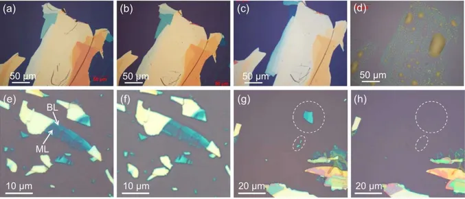
relevance for electronic applications (see Section 1.2.1). Similar considerations suggested the introduction of the expression ‘electronic-grade BP’ with reference to a form of BP characterized by a high degree of crystallinity and purity, with optimal performance in BP-based FETs. Historically, top-down methods were used first. Indeed, when 2D BP was prepared for the first time independently by Y. Zhang [56] and P.P. Ye [40] groups back in 2014, the exfoliation of BP crystals was carried out mechanically, using a classical adhesive-tape method (also termed micromechanical cleavage). This technique is well established in the field of nanoscience, being developed in 2004, when A. Geim and K. Novoselov used it to prepare graphene from graphite [57]. In a typical procedure, the crystal of a 2D material is attached to a piece of adhesive tape, supposed to have with the material an adhesion stronger than that existing between adjacent layers. Another tape is also attached to the crystal, at the opposite face, and then it is peeled off. The weak interlayers interactions are easily broken, and flakes of the material remain stacked on the tape, to be later transferred on a support (e.g. SiO2/Si). In Figure 12a, a
representative example of micromechanical cleavage of bulk BP is shown. Repeating the procedure on the detached flakes, thinner and thinner structures are successively obtained, even composed of few monolayers (FL-BP). In Figure 12b, the AFM image of a mechanically cleaved flake reported by Peide Ye’s group, demonstrating the possibility to reach even single monolayers (1L-BP, or phosphorene), is reported.
Figure 12. a) Representative mechanical exfoliation of a BP flake. In this example, a PDMS tape is used to peel off the material. After delamination, the material can be transferred to the target substrate, Ge-coated PDMS in this case.
Reproduced from reference [58]. b)-d) Material characterizations of single-layer and few-layer phosphorene. b) AFM image of a single-layer phosphorene flake with the measured thickness of ~ 0.85 nm. Reproduced from reference [56]. c)
Photoluminescence spectra for single-layer phosphorene and bulk black phosphorus samples on a 300 nm SiO2/Si substrate,
showing a pronounced PL signal around 1.45 eV. To prevent the single-layer phosphorene reacting with the environment, it is covered by PMMA layer during experiments. d) Raman spectra of single-layer and bilayer phosphorene and bulk black phosphorus films. Reproduced from reference [40].
Mechanical exfoliation allows the isolation of flakes having larger lateral dimensions compared to other top-down methods (i.e. solvent assisted and electrochemical exfoliation, see below). It also keeps the
16
crystallinity of the material perfectly unaltered and allows to obtain very thin flakes suited for electronic applications. However, a major limitation of this approach is the intrinsic poor yield, with no possible scaling. Thus, if a massive amount of material is needed, distinct approaches must be used, the most common being liquid phase exfoliation (LPE). As for micromechanical cleavage, LPE had been widely applied to other materials such as graphite [59], g-C3N4 [60], TMDCs [61] or h-BN [62]. The method
consists in dipping a bulk crystal inside a suitable solvent and then using ultrasounds to achieve the exfoliation. Sonication generates cavitation bubbles inside the solvent. The latter collapse generating shock waves, which propagate and disrupt the BP structures, peeling the layers apart with formation of 2D BP flakes. In practice, ultrasounds may be generated using a sonication tip immersed inside the solvent. Alternatively, the chosen solvent and BP microcrystals are sealed inside a glass ampoule which is then immersed in a refrigerated ultrasonic bath. As 2D BP is sensitive to oxidation, the solvent is first degassed aiming to exclude oxygen during exfoliation. The role of solvent is not just that of a mere propagating medium for shock waves, actually its molecules should interact effectively with the surface of BP and provide stabilization to the layers, enabling their separation. Of course, in addition to the choice of solvent different factors are crucial to control the quality and the dimensions of 2D BP flakes, including sonication power (typically 20-50 KHz), time (some hours, usually more than 10) and temperature (around 20°C). In 2014, J.R. Brent et al. [63] were the first to carry out the LPE of BP. They used N-methyl-2-pyrrolidone (NMP) as solvent and obtained flakes that ranged from larger ones 200 x 200 nm with thickness 5 nm (11 layers) to smaller 20 x 20 nm and made of just 2-3 layers. The LPE process, beyond the separation of flakes, exerts the fragmentation as well, thus different flakes are produced, whose size and thickness are spread over a large interval of magnitude. An effective exfoliation protocol should produce homogeneous flakes, namely characterized by a sharp size distribution. Typically, increasing the sonication time helps reaching thinner flakes on one side, but causes breaks on the other, with a reduction in flakes average dimensions. M.C. Hersam et al. [64] studied the exfoliation of BP in different organic solvents, using a sealed-tip sonication apparatus (see Figure 13).
17
Figure 13. a) Schematic and (b) photograph of the custom-tip ultrasonication setup that minimized exposure to ambient air during processing described in reference [64]. c) 2D BP suspension in NMP obtained after ultrasonication (left), 5000 rpm centrifugation and 15000 rpm centrifugation (right). BP concentration after 5000 rpm centrifugation evaluated by UV/VIS absorption spectroscopy for various solvents as a function of boiling point (d) and surface tension (e). The red markers in (d) represents the value before centrifugation (immediately after ultrasonication). f) Photograph of 2D BP dispersions in DMSO and DMF solvents after sonication (left) and after centrifugation and supernatant collection (right). Reproduced from reference [65]. g) Optical absorption spectra obtained from dispersions in DMSO and DMF and (h) Absorbance normalized to the characteristic length of the cell at different concentrations (λ = 1176 nm). The extinction coefficient α extracted was used to evaluate the concentration of the subsequent solutions. i) DLS histogram for DMSO and DMF solution showing the flake lateral size distribution. j) Schematic of the preparation method for FL-BP aqueous dispersions described in reference [66]. Water with 2% (wt/vol) SDS was deoxygenated with Ar purging. The BP crystal was exfoliated in a sealed container using tip ultrasonication and then centrifuged to remove unexfoliated BP crystals and to isolate the FL-BP suspension. k) TEM image of a FL-BP flake obtained by this method.
Afterwards, centrifugation was carried out to separate the heavier fraction of the exfoliated material, the concentration of thin flakes left in solution was evaluated via UV-Vis absorbance measurements. This concentration indeed may be considered a figure of merit of the ability to sustain the peeling of BP into few-layer flakes, and it turned out that polar aprotic solvents with a high dielectric constant are the best suited for LPE (see Figure 13e,h). As revealed by microscopy (Figure 13k), spectroscopic (XPS, Raman) and electron diffraction studies, 2D BP flakes prepared by LPE in organic solvents are pure, structurally
18
intact and morphologically comparable to mechanically exfoliated ones. Furthermore, FETs built with solvent exfoliated flakes showed current on/off ratios and mobilities up to ∼104 and ∼ 50 cm2 V-1 s-1
respectively, lower but still comparable to mechanically exfoliated flakes [64]. Further studies showed that DMSO is also extremely effective for LPE, with similar performance to DMF in terms of exfoliating ability (evaluated by the concentration of the final suspension) and flake size distribution (see Figure 13j). M. Serrano-Ruiz et al. [67] carried out a detailed investigation on the use of DMSO in BP LPE, studying the effect of added water on the morphology of the exfoliated material. Surprisingly, it turned out that water is a non-innocent player during the exfoliation of BP in DMSO. Remarkably, while common DMSO always contains some traces of water, being very hygroscopic, using rigorously anhydrous DMSO leaded to decomposition of BP under sonication, despite all manipulations were carried out under nitrogen. When small amounts of deoxygenated water were added, 2D BP flakes were successfully obtained, whose homogeneity and dimensions were function of the specific P/H2O molar
ratio. The best results came using 1.5 < P/H2O < 14, which yielded brown suspensions. After
centrifugation (6000 rpm x 1h) a heavier fraction was isolated, composed of thicker flakes (30-100 nm), while FL-BP flakes with average size 500 x 800 nm2 and thickness 5-20 nm remained in suspension.
M.C. Hersam and coworkers have demonstrated that BP can be successfully exfoliated in water if stabilizing surfactant (sodium dodecylsuplhate) are present [66]. By this method, homogeneous suspensions of thin flakes with mean lateral size 150 nm and thickness 5 ± 4 nm were obtained. However, despite being electronically and optically active, these flakes likely bear traces of surfactant impurities, which may prevent subsequent chemical applications of the material. An advantage of LPE compared to mechanical exfoliation is that, in addition to peeling bulk BP into 2D BP flakes, the solvent may provide a barrier toward oxidation, provided that its molecules have a strong affinity with the surface of BP and get adsorbed creating a protective film. D. Hanlon et al. [68] found out that using N-cyclohexyl-2-pyrrolidone (CHP), BP crystal could be exfoliated even under ambient conditions without particular precaution (i.e. solvent deoxygenation, maintenance of inert atmosphere), as revealed by statistical Raman measurements. Indeed, A1
g/A2g intensity ratios were sampled in 120 flakes, and always
the ratio turned out > 0.6, strongly suggesting the absence of layer oxidation. Other useful solvents for both LPE and stabilization of exfoliated 2D BP are ionic liquids (ILs, see Figure 14). [69-72]. The latter are organic salts typically formed by an alkyl-imidazolium cation and a non-coordinating anion (BF4-,
PF6-, ClO4-, TfO- are the most common). Due to packaging difficulties in the solid state, these
compounds are liquid at room temperature. ILs possess several interesting properties, such as high dielectric constant and viscosity, non-toxicity and easy recyclability compared to common organic solvents, thus representing a greener alternative.
19
Figure 14. a-d) Optical characterization of IL-exfoliated BP nanosheets reported in reference [71]. a) Photograph of the 2D BP dispersions in [BMIM][TfO] and [HOEMIM][TfO] (left) and the Tyndall effect of diluted dispersions (right). b) Raman spectra of bulk BP and IL-exfoliated BP nanosheets in [BMIM][TfO] and [HOEMIM][TfO]. c) Plots of absorbance normalized to the length of the cell at different concentrations of BP for λ = 1188 nm in [BMIM][TfO] and [HOEMIM][TfO]. d) Size distribution histograms of IL-exfoliated BP nanoflakes in [BMIM][TfO] and [HOEMIM][TfO]. e) Molecular representation of phosphorene in [HMIM][BF4]. Reproduced from reference [72].
Despite a π-p interaction between the electron-poor aromatic ring of imidazolium cations and BP lone pairs would be expected, recent theoretical calculations carried out by V.V. Chaban and coworkers [70] highlighted that the major contribution in this interaction comes from dispersion forces between BP and the lateral hydrophobic chains of the alkyl imidazolium cation. Polar imidazole rings instead form an electrostatically stabilized protective layer, limiting surface oxidation (see also Section 1.3.2). This effective interaction and the high viscosity of the solvent made possible to prepare stable 2D BP/ILs suspensions having concentration as high as ~ 1 mg/mL [71]. Although the yield and efficiency of LPE process have been largely improved in comparison to the mechanical exfoliation, alternative liquid-phase assisted methods have been proposed such as microwave [73] and solvothermal assisted methods [74]. Electrochemical exfoliation in particular has received some attention, since this method was previously employed successfully with graphene, giving high quality nanosheets by a simple, fast and environmental-friendly procedure, based on the use of water instead of organic solvents. In this process, bulk BP crystals are used as anodic material in a two-electrode cell with aqueous electrolyte. A constant potential difference is applied between the cathode and a counter electrode. As oxygen evolution starts to occur at the anode, electric current curses the BP crystals leading to layers detachment. M.B. Erande et al. [75] reported the preparation of 2D BP by this method using Pt wire as counter-electrode, working with 0.5 M aqueous Na2SO4 as electrolyte and an applied potential of 7 V. As shown in Figure 15e,f,g
BP flakes obtained by this method displayed remarkable big lateral dimensions (0.5-30 µm), combined with a small thickness (3-15 layers).
20
Figure 15. Electrochemical exfoliation procedure reported in reference [76]. a) Bulk BP is exfoliated in an acidic aqueous solution by the application of a DC voltage. The starting BP crystals (left) and the exfoliated material dispersion in DMF (right) are shown. b1) The electrochemical setup with the BP-flake anode and Pt-foil cathode, in acidic solution (H2SO4 0.5 M),
separated by a fixed distance of 2 cm at no potential applied, (b2) after 20 min applying a voltage of +3 V, and (b3) after 2 h of applied voltage. c) Survey XPS spectrum of bulk and electrochemically exfoliated BP (BP-EC-Exf) and (d) Corresponding core level P2p XPS spectra. Cu was an impurity due to the sample holder. e)-g) Characterization of electrochemically exfoliated 2D BP described in reference [75]. e1, e2) TEM images of 2D-BP nanosheets and. f1) SAED pattern and (f2) HRTEM image of 2D BP highlighting the morphological integrity and the crystallinity of the material. g1) AFM imaging of a thin flake and (g2) corresponding height profile.
Similarly, M. Pumera and coworkers [76] reported the synthesis of 2D BP working in 0.5 M H2SO4
under a voltage of 3 V applied between the working electrode (BP) and Pt wire (see Figure 15a,b). As highlighted by XPS data, 2D BP flakes prepared by anodic exfoliation are partially oxidized, due to the intrinsic nature of the process (see Figure 15d). Nonetheless, M.B. Erande and coworkers assembled FETs using electrochemically exfoliated flakes and measured a field effect mobility and current ON/OFF ratio of 7.3 cm2V-1s-1 and ~ 104 respectively, thus comparable to values obtained using different
exfoliation protocols. A related electrochemical method was reported by the same group of M. Pumera [77] based on the concepts of bipolar electrochemistry. When immersed in the strong electric field generated by two parallel electrodes, BP crystal gets polarized at their opposite extremities and a potential difference builds up across each crystal, inducing fragmentation into smaller flakes. In practice, using two Pt foils as electrodes and a voltage as high as 10 V, BP microcrystals could be exfoliated into BP nanoparticles, with hydrodynamic radius ~ 70 nm. To overcome the problem of BP oxidation during the process of anodic exfoliation (due to the formation of oxidizing species as O2), M. Lu and X. Xie
have demonstrated that bulk BP can be efficiently exfoliated under a cathodic potential in an aqueous solution of hexadecyltrimethylammonium chloride [78]. The cation of the surfactant acts as intercalating
21
agent and applying the suitable voltage, BP can be peeled off in 30 minutes, once the temperature is raised to 50°C (meanwhile at RT the process did not take place). Whilst LPE requires many hours, this route is much faster and has the advantage of not using organic solvents and being easier to scale-up. BP quantum dots (BPQDs). Quantum dots are semiconducting nanoparticles that possess unique optical and electronic properties, due to quantum confinement effects. Compared to BP nanosheets, BPQDs are 0D-nanostructures. Thus, despite being composed of stacked monolayers, their shape lacks the bidimensionality of 2D BP and their lateral-size-to-thickness ratio approaches 1, with absolute dimensions typically in the range 3−10 nm [79]. Though most research efforts focused on 2D BP, many studies on BPQDs have also been reported, mainly addressed to exploit their optical properties for biomedical applications such as fluorescence imaging, photoacoustic imaging and photothermal cancer therapy. BPQDs are usually prepared using LPE methods, both via tip and bath sonication or a combination of the two. The preferential formation of 0D-structure (BPQDs) compared to 2D nanosheets is dictated solely by the specific conditions under which LPE is carried out. For instance, Z. Sun et al. [80] synthetized BPQDs with ultrasound probe sonication followed by ice-bath sonication of bulk BP powder in NMP, producing high quality BPQDs with lateral dimension 2.6 ± 1.8 nm and average thickness 1.5 ± 0.6 nm (see Figure 16). H. Zhang et al. [81] reported the synthesis of BPQDs with lateral dimensions 4.9 ± 1.6 nm and thickness 1.9 ± 0.9 nm by ice-bath sonication in NMP (200 W x 3 h) followed by centrifugation to eliminate heavier particles. Other procedures using different solvents from NMP were reported, including N-vinyl-pyrrolidone, isopropyl alcohol, and DMF [79]. In addition to sonochemical exfoliation, some procedures based on solvothermal methods have been reported to prepare BPQDs.
22
Figure 16. Synthesis and characterization of BPQDs from reference [80] a) Procedure of BPQDs synthesis by LPE. b) and (c) TEM imaging of BPQDs. d) HRTEM detail of a BPQD. The scale bar is 1 nm. e) AFM image and (f) height profiles measured along the red lines in (e). g) Statistical analysis of the lateral sizes and (h) thickness of 100 BPQDs as determined by TEM and AFM, respectively. i) XPS spectrum, showing a significative P−O contribution. j) Raman spectra of bulk BP and BPQDs.
These preparations exploit the combined effect of high temperature, solvent stabilization and mechanical shear-stress exerted by a magnetic stirring bar to exfoliate bulk BP. Ultrasmall BPQDs with average dimension 1.76 ± 0.32 nm were synthesized by W. Gu et al. [82] stirring BP powder in NMR at 140°C for 12 h, under N2 atmosphere. Y. Xu et al. [83] followed a similar procedure but working with NaOH
saturated solutions in NMP. After 6 h of vigorous stirring at 140°C, BPQDs with dimensions 2.1 ± 0.9 were isolated in suspension after centrifugation. Though NaOH saturated NMP has been used also in the LPE of BP [84], some doubts concern the stability of 2D BP toward high OH- concentrations in solution (see also Section 1.3.1). However, no XPS measurements were reported which would shed light on the presence of P−OH bonds.
1.2.3 Experimental characterization of exfoliated BP
Before moving towards the study of BP chemical reactivity, it’s worth to spend some time describing how BP appears under the common experimental characterization techniques. The latter include spectroscopy, microscopy, and crystallography. Whilst these tools allow to establish the morphology and chemical purity of 2D BP, they make also possible to study surface and structure alteration following oxidation or chemical functionalization. Atomic-scale microscopy techniques (HRTEM, STEM, STM)
23
have been developed rapidly over the last ten years, allowing a clear visualization of local structural features and even atoms connectivity in materials (see Figure 17). Figure 17e shows an atomic scale image of the armchair direction along the edge of a BP nanosheet, obtained through aberration corrected STEM.
Figure 17. a) Transmission mode optical microscopy image of a few-layer black phosphorus flake exfoliated onto a PDMS substrate, featuring the reduction of about 5.5% in optical transmittance in the thinner part of the flake and (b) bright field optical microscopy image of the same flake after transferring it onto a SiO2/Si substrate. c) AFM topography image and height
profile of the region highlighted in (b). Reproduced from reference [85]. d) ADF-STEM image of a BP flake viewed along the b axis direction and (d1) upon 17° tilting of the b axis. (e) ADF-STEM viewed along the zigzag direction, showing multiple layers stacked together. e1) Magnified image of the region highlighted in (e) featuring the puckered motif of the layers. Reproduced from reference [86]. f) SAED pattern and (g) HRTEM image of a BP flake, indicating the presence of crystalline BP. Reproduced from reference [87]. h) Powder XRD spectrum of 2D BP featuring just three peaks corresponding to (0k0) reflections. Reproduced from reference [88]. For comparison purpose, the powder pattern calculated for bulk BP is shown in (h1). (0k0) reflections are highlighted in red.
High resolution TEM (HRTEM) is often used to study crystalline domains and to measure crystallographic distances, thus leading to phase characterization and identification at the nanometric scale. Scanning tunnelling microscopy (STM) as well allows to carry out atomic-level characterization of surfaces and even to study defective structures. Atomic force microscopy (AFM) is frequently employed to study the morphology of 2D BP flakes and to measure their thickness (see Figure 17c). This magnitude, together with the knowledge of the interlayer distance in BP of ~ 0.53 Å, allows to give an estimate of the layers number. When the material is a powder instead of bulk crystals, as it is the case of exfoliated BP, powder XRD measurement are usually carried out to assess the crystallinity and phase purity of the sample. The powder spectrum of a material has finger-print characteristic and provides a safe identification of a crystalline phase by simple comparison with a reference pattern. When BP is exfoliated and mounted in a sample holder for XRD measurements, its flakes are never randomly
24
oriented inside the sample, but tend to pile up. This behaviour, known as ‘preferential orientation’, is typical of exfoliated 2D materials and other specimens consisting in platelet or needle-shaped particles. If a random orientation is suppressed, the overall effect in the powder spectrum is an alteration of the peak relative intensities, as some reflections will be over-represented at the expense of others. This can even lead to the complete absence of some reflections in the spectrum. In case of 2D BP the effect is significant, giving XRD patterns dominated by (0k0) reflections, as shown in Figure 17h.
Raman spectroscopy is frequently used to characterize 2D BP samples. The reducible representation of atomic displacement parameters is Γ = 2Ag ⨁ B1g ⨁ B2g ⨁ 2B3g ⨁ Au ⨁ 2B1u ⨁ 2B2u ⨁ B3u. Of these
vibration modes the only Raman active are the six with even parity (g), thus 2Ag ⨁ B1g ⨁ B2g ⨁ 2B3g.
Because of the preferential orientation effect described above, the flakes lay with the b⃗ axis orthogonal to the surface of the sample holder during the measurement. In the backscattering configuration of Raman experiments, the laser beam reaches the surface perpendicularly, thus parallel to b⃗. Under these conditions, because of the symmetry selection rule, the only visible modes are A1
g, B2g, A2g, which are
observed at ~ 357.8, ~ 431.5, and ~ 459.2 cm-1, respectively (see Figure 18a,b). The actual values may
vary depending on the reference, in addition to other physical factors (flake thickness, oxidation, etc), as described below.
Figure 18. a) Representative average Raman spectrum measured out of 15 BP flakes. b) Atom displacements (green arrows) for the Raman-active modes. Axes indicate two view perspectives. Reproduced from reference [89]. c) Experimental Raman spectrum of 2D-BP. Inset: the zoom-in spectrum from 20 to 150 cm−1, the dotted lineshapes show the three fitted Lorentzian B
modes. c1) Calculated Raman spectrum of 6L-BP in the experimental backscattering geometry. Inset: the zoom-in spectrum in the same LF region as (c). Reproduced from [90]. d) Raman spectra of bulk BP and 2D BP with different numbers of layers. Reproduced from reference [84]. e) Polarized Raman spectra (parallel polarization) of BP measured with 441.6 nm excitation.
25
The angle between the incident polarization and the zigzag direction for each spectrum is indicated. Reproduced from reference [91].
These three Raman modes are the only predicted for bulk BP and phosphorene (1L-BP), and correspond to intra-layer vibrations. In detail, A1
g stands for the out-of-plane phonon mode, while B2g and A2g are
the two in-plane modes. Taking into account FL-BP flakes containing n layers (nL-BP), low-frequency (LF) inter-layer modes are predicted in addition to the three high-frequency (HF) shifts just described. LF vibrations involve sliding of adjacent layers (shear-modes) or their separation (breathing-modes). With backscattering geometries, only breathing modes with B symmetry are visible, whose number is n/2 or (n – 1)/2 for even or odd values of n, respectively (see Figure 18c). However, LF vibrations are seldom observed, as their intensities are much weaker compared to the three HF modes, and because Raman signals < 100 cm-1 are usually cut off by the notch filters used to reject the excitation light. Thus,
in the rest of this manuscript, any reference to BP Raman peaks will refer to the three HF vibrations A1 g,
B2g, A2g. Experimental results by Z. Guo et al. [84] highlighted a progressive red-shift upon increase in
the number of layers (see Figure 18d). The A2
g modes turned out to be the most sensitive, with a
red-shift (i.e. downred-shift) of -2.6 cm-1 going from 1L-BP to 4L-BP. These differences are larger than the
experimental uncertainty, which for most Raman spectrometers is ~ 0.5 cm-1. The existence of a
layer-dependence in Raman peak should always be taken into account dealing with flakes prepared via LPE. In this situation, in order to compare distinct samples (e.g. before and after chemical functionalization), Raman spectra should be acquired first on a statistical ensemble of flakes and then averaged to get one representative spectrum of each sample. Then, only the two averaged spectra should be compared. As most Raman measurements are performed on flakes supported on SiO2/Si, the characteristic peak of Si
at ~ 520 cm-1 is frequently used as internal standard to normalize the other peaks. An additional feature
of Raman spectroscopy is that it is polarization sensitive. As it was highlighted in distinct theoretical and experimental studies, the intensity of the three Raman peaks is a function of polarization angle and flake orientation (see Figure 18e). Exploiting this characteristic, a procedure to determine the crystallographic orientation of a flake via Raman measurements has been devised [92]. Another useful application of Raman spectroscopy is to monitor the progress of surface oxidation in BP flakes during environmental-stability tests. Indeed, as better described in Section 1.3.1, Raman intensities drops over time upon oxidative damage, providing a straightforward method to follow the kinetics of the process. Furthermore, some reports highlight Raman frequency shifts following surface functionalization. Though surface modification could definitely led to this effect, care should always be taken comparing spectra of distinct samples, as explained above. Infrared spectroscopy (IR), both in transmittance and attenuated total reflectance (ATR) mode, is less frequently used with BP samples, being limited by the high absorption coefficient of BP in the NIR-IR region, and by the absence of characteristic spectral features in pristine BP. IR measurements has been used to highlight the presence of oxidation products

![Figure 13. a) Schematic and (b) photograph of the custom-tip ultrasonication setup that minimized exposure to ambient air during processing described in reference [64]](https://thumb-eu.123doks.com/thumbv2/123dokorg/4626451.40767/25.892.139.843.114.679/schematic-photograph-ultrasonication-minimized-exposure-processing-described-reference.webp)
![Figure 14. a-d) Optical characterization of IL-exfoliated BP nanosheets reported in reference [71]](https://thumb-eu.123doks.com/thumbv2/123dokorg/4626451.40767/27.892.126.847.115.364/figure-optical-characterization-il-exfoliated-nanosheets-reported-reference.webp)