2018
Publication Year
2021-01-04T10:29:12Z
Acceptance in OA@INAF
The AIV concept of SHARK-NIR, a new coronagraph for the Large Binocular
Telescope
Title
MARAFATTO, Luca; BERGOMI, Maria; BIONDI, FEDERICO; CAROLO, ELENA;
CHINELLATO, SIMONETTA; et al.
Authors
10.1117/12.2314250
DOI
http://hdl.handle.net/20.500.12386/29411
Handle
PROCEEDINGS OF SPIE
Series
10702
Number
PROCEEDINGS OF SPIE
SPIEDigitalLibrary.org/conference-proceedings-of-spie
The AIV concept of SHARK-NIR, a
new coronagraph for the Large
Binocular Telescope
Marafatto, Luca, Bergomi, Maria, Biondi, Federico, Carolo,
Elena, Chinellato, Simonetta, et al.
Luca Marafatto, Maria Bergomi Jr., Federico Biondi, Elena Carolo, Simonetta
Chinellato, Marco De Pascale, Marco Dima, Jacopo Farinato, Davide
Greggio, Luigi Lessio, Demetrio Magrin, Elisa Portaluri, Roberto Ragazzoni,
Daniele Vassallo, Valentina Viotto, "The AIV concept of SHARK-NIR, a new
coronagraph for the Large Binocular Telescope," Proc. SPIE 10702,
Ground-based and Airborne Instrumentation for Astronomy VII, 107024C (27 July
2018); doi: 10.1117/12.2314250
Event: SPIE Astronomical Telescopes + Instrumentation, 2018, Austin, Texas,
United States
The AIV concept of SHARK-NIR, a new coronagraph for the Large
Binocular Telescope
Luca Marafatto
a, Maria Bergomi
a, Federico Biondi
a, Elena Carolo
a, Simonetta Chinellato
a, Marco
De Pascale
a, Marco Dima
a, Jacopo Farinato
a, Davide Greggio
a, Luigi Lessio
a, Demetrio Magrin
a,
Elisa Portaluri
a, Roberto Ragazzoni
a, Daniele Vassallo
a, Valentina Viotto
aa
INAF – Osservatorio Astronomico di Padova, Vicolo dell’Osservatorio 5, Padova, 30122, Italy
ABSTRACT
SHARK-NIR is one of the forthcoming instruments of the Large Binocular Telescope second generation instruments. Due to its coronagraphic nature, coupled with low resolution spectroscopy capabilities, it will be mainly devoted to exoplanetary science, but its FoV of 18 x 18 arcsec and very high contrast imaging capabilities will allow to exploit also other intriguing scientific cases.
The instrument has been conceived and designed to fully exploit the exquisite adaptive optics correction delivered by the FLAO module, which will be improved with the SOUL upgrade, and will implement different coronagraphic techniques, with contrast as high as 10-6 up to 65 mas from the star.
Despite the wavelength range of SHARK-NIR is 0.96-1.7 um, the instrument is designed to work in synergy with SHARK-VIS and with LMIRcam, on board of LBTI. The contemporary acquisition from these instruments will extend the wavelength coverage from M band down to the visible radiation.
The physical location of the instrument, at the entrance of LBTI, imposes dimensional constraints to the instrument, which had been kept very compact. The folded optical design includes more than 50 optical elements, among which 4 Off-Axis Parabolas, 1 Deformable Mirror for the compensation of the Non Common Path Aberrations from the FLAO Wavefront Sensor, 2 detectors and 3 different kinds of coronagraph: Gaussian Lyot, Shaped Pupil and Four Quadrant Pupil Mask. Most of these optics are located onto an optical bench 500 x 400 mm, which makes SHARK-NIR an extremely dense instrument. This, together with the presence of 4 off-axis parabolas and of coronagraphs, such as the Four Quadrant, poorly tolerant to misalignments, requires a careful alignment and test phase, which needs the fine adjustement of many hundreds of degrees of freedom.
We will give here an overview of the opto-mechanical layout of SHARK-NIR and of the identified alignment procedure, mostly optical, planned to take place in 2018.
1. INTRODUCTION
SHARK is an instrument proposed for LBT in the framework of the “2014 Call for Proposals for Instrument Upgrades and New Instruments” and accepted for construction in January 2017. It is composed by two channels, a visible and a near infrared arm, to be installed one for each LBT telescope arm, and it will exploit, in its binocular fashion, unique challenging science from exoplanet to extragalactic topics with simultaneous spectral coverage from R to H band, taking advantage of the outstanding performances of the binocular XAO LBT capability.
SHARK-NIR will observe in the near-infrared wavebands, 0.96 – 1.7 μm, and it will be located at the central bent Gregorian focal station of the LBT, on the SX side. Since this focal station is shared with LBTI, a dichroic can be deployed in order to pick the NIR light for SHARK-NIR, letting the visible part of the spectrum reaching the FLAO wavefront sensor, soon upgraded to SOUL.
SHARK-NIR [1] [2] is basically a camera for direct imaging, coronagraphy and spectroscopy, using the corrected wavefront provided by the LBT Adaptive Secondary Mirror (ASM).
Due to its coronagraphic nature, the camera shall accomplish an exquisite performance, ideally maintaining the Strehl Ratio provided by the AO system. In orded to achieve this, the optics are polished to a nanometric level, and they must be properly aligned. The instrument will be installed in a very crowded area of the telescope, where another instrument is already installed (LBTI). For this reason the instrument must be very compact, and thus it uses a folded optical design,
Ground-based and Airborne Instrumentation for Astronomy VII, edited by Christopher J. Evans, Luc Simard, Hideki Takami, Proc. of SPIE Vol. 10702, 107024C · © 2018 SPIE · CCC code: 0277-786X/18/$18 · doi: 10.1117/12.2314250
Proc. of SPIE Vol. 10702 107024C-1 Downloaded From: https://www.spiedigitallibrary.org/conference-proceedings-of-spie on 20 Nov 2020
using 4 off-axis parabolic mirror to produce 2 pupil planes and 2 focal planes, allowing the implementation of 3 different coronagraphic techniques: Gaussian, Shaped Pupils, Four Quadrant.
Coronagraphic masks are usually extremely sensitive to misalignments and thus a precise and complete removal of vibrations is crucial to achieve the theoretical contrast of the coronagraph. For this reason, SHARK-NIR is equipped with a Deformable Mirror (DM) and a technical camera for fast tip-tilt correction. The DM allows also the compensation of the Non Common Path Aberrations (NCPA) between the instrument and the AO system, which is the FLAO for LBTI.
In addition, to maintain a good performance at any elevation angle, it is necessary to compensate for the atmospheric dispersion and thus the instrument is equipped with an ADC.
The NIR camera, based on an Teledyne H2RG detector, cooled at about 80°K to minimize the thermal background, will provide a FoV of the order of 18”x18”, with a plate scale foreseeing a bit more than two pixels on the diffraction limit PSF at 1μm.
Finally, since some of the scientific cases of SHARK-NIR requires field de-rotation, the whole optical bench of SHARK-NIR is mounted onto a bearing.
2. THE OPTO-MECHANICAL LAYOUT
As mentioned in the introduction, the opto-mechanical layout of SHARK-NIR is quite compact, in order to fit the instrument into a limited space.
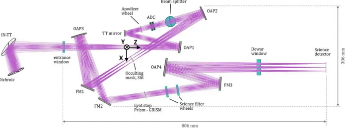
The F/15 beam coming from the telescope is collimated by the first off-axis parabola (OAP1), to produce an image of the entrance pupil onto the DM. This is an ALPAO 97-15 with a 13.5 mm diameter and 97 acuators, with 30 μm stroke and 2 KHz bandwidth.
A wheel at 50 mm from the pupil plane allows to select among different apodizing masks and, immediately after, there is the ADC.
After the ADC, a beam-splitter (BS) sends part of the light, ~ 5%, to a tip-tilt sensor, constituted of a lens and a commercial camera sensitive to J band (CRED-2 from First Light). The tip-tilt sensor is used to monitor the shifts of the reference star at very high frequency, in order to cope with the residual jitter of the telescope not removed by the FLAO. The signal from this camera is analysed by a Real Time Computer from Microgate, which commands the DM for compensation of the jitter.
The remaining 95% of the light is re-focused by OAP2 to an intermediate focal plane, where a filter wheel can select among different coronagraphic masks (9 positions available in the wheel). After a folding mirror, a third off-axis parabola (OAP3) is creating the second re-imaged pupil plane, where a filter wheel (8 positions foreseen) can select between different pupil stops used to properly mask the spiders.
Two wheels with 8 positions each will allow to insert in the path several scientific filters, both broadband and narrowband. A fourth off-axis parabola (OAP4) is creating the final focal plane onto the detector. A deployable small optical group (Pupil Re-Imager, PRI), not shown in Figure 1, can be inserted between OAP4 and the cryostat window, with the purpose to create an image of the pupil onto the detector, which can be used before each scientific exposure to properly calibrate and compensate pupil shifts.
Since the instrument has a Wollaston prism in the second pupil plane and support Dual Band Imaging (DBI), a further wheel hosting specific filters for DBI is placed just before cryostat window.
A Narcissus mirror just before the cryostat window will also help to minimize the thermal background entering into the scientific camera.
The whole optical bench is protected from outer environment with carters and it is kept in slight overpressure with respect to ambient.
For calibration purposes, the instrument is equipped with two fibers at the entrance focal plane of the instrument. These fibers are mounted on a motorized linear stage that deploys them in and out the optical path. One of the fiber will simulate a focused on-axis star on the scientific camera, while the second fiber will be slightly out of focus, and will be used to perform Phase Diversity [3].
For flat fielding of the scientific detector and for spectral calibration of the instrument, an integrating sphere is also part of the calibration unit. This can be fed with quasi black-body light for flat fielding and with 5 different wavelengths for
Proc. of SPIE Vol. 10702 107024C-2 Downloaded From: https://www.spiedigitallibrary.org/conference-proceedings-of-spie on 20 Nov 2020
IN-TT OAP3 Apodizer wheel
\ ADC
Beam splitter Dewarwindow Sciencedetector
Dichroic lyotstop Prism - GRISM Science filter wheels 806 mm E E enm 0
Off -axis parabolas (1,2,4)
Apodizers wheel ADC
DM
CRED2
Off -axis parabola (3)
Dichroic
spectral calibration. A lens produces an image of the output port at the entrance focal plane of the instrument, and thus also on the scientific camera, properly rescaled to illuminate all the useful area.
Figure 1: Optical design of SHARK-NIR (top-view of the optical bench). The light enters the instrument from the left.
Figure 2: Opto-mechanical layout of SHARK-NIR optical bench.
Proc. of SPIE Vol. 10702 107024C-3 Downloaded From: https://www.spiedigitallibrary.org/conference-proceedings-of-spie on 20 Nov 2020
3. SHARK-NIR AIT PLAN
The philosophy of the AIT phase of SHARK-NIR foresees the testing of all the optical elements in terms of Transmitted Wavefront Error (TWE) for the transmissive optics and in terms of Surface Accuracy (SA) for the reflective optics. As said before, the performance of the instrument shall not degrade the wavefront delivered by the AO system, and thus all the optics must have very low TWE and SA (of the order of λ/30 for TWE and λ/50 for SA, with λ = 632.8 nm). Details on the overall error budget for SHARK-NIR are given in [3].
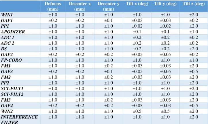
All these components, if not tested by the providing company, are tested at Padova premises using a Zygo interferometer and double pass setup for transmissive optics, and single pass for flat mirrors and double pass for parabolic mirrors. In order to assess the sensitivity to misalignment of optical components at system level we performed a preliminary tolerance analysis on the science channel, based on Montecarlo simulations, whose results are listed in Table 1.
Defocus
(mm)
Decenter x
(mm)
Decenter y
(mm)
Tilt x (deg)
Tilt y (deg)
Tilt z (deg)
WIN1
±1.0
±1.0
±1.0
±1.0
±1.0
±2.0
OAP1
±0.2
±0.2
±0.1
±0.03
±0.03
±0.2
PP1
±1.0
±1.0
±1.0
±0.02
±0.02
±2.0
APODIZER
±1.0
±1.0
±1.0
±0.1
±0.1
±1.0
ADC 1
±1.0
±1.0
±1.0
±0.2
±0.2
±0.2
ADC 2
±1.0
±1.0
±1.0
±0.2
±0.2
±0.2
BS
±1.0
±1.0
±1.0
±0.2
±0.2
±2.0
OAP2
±0.2
±0.2
±0.2
±0.05
±0.05
±0.2
FP-CORO
±1.0
±1.0
±1.0
±1.0
±1.0
±1.0
FM1
±1.0
±1.0
±0.2
±0.03
±0.03
±2.0
OAP3
±0.2
±0.2
±0.1
±0.05
±0.05
±0.5
FM2
±1.0
±1.0
±0.2
±0.03
±0.03
±2.0
PP2
±1.0
±1.0
±1.0
±1.0
±1.0
±2.0
SCI-FILT1
±1.0
±1.0
±1.0
±1.0
±1.0
±2.0
SCI-FILT2
±1.0
±1.0
±1.0
±1.0
±1.0
±2.0
FM3
±1.0
±1.0
±0.2
±0.03
±0.03
±2.0
OAP4
±0.2
±0.2
±0.2
±0.03
±0.03
±0.5
WIN2
±1.0
±1.0
±1.0
±0.5
±0.5
±2.0
INTERFERENCE
FILTER
±1.0
±1.0
±1.0
±1.0
±1.0
±2.0
Table 1: Tolerances for each optical element estimated from the sensitivity analysis.
The results of the analysis drove the AIT plan and the requirements to the mechanical mounts of the optics, especially in terms of minimum incremental step for tilt and focus adjustments that should be, as a rule of thumb, a factor 10 better than the alignment budget.
All the motorized stages, used to deploy/switch among different coronagraphic masks, have been tested in Padova to verify their repeatability, crucial to maintain the alignment among the masks during the science operations, using both their native electronics and the final electronics used in SHARK-NIR.
After the testing phase at sub-system level, the AIT plan foresees the alignment of the instrument at system level, starting aligning the main path, constituted by 4 off-axis parabolic mirrors and 3 flat mirrors.
The alignment is aided by a spatially filtered narrow laser beam, for the definition of the optical axis of the instrument, which must be aligned to the bearing rotation axis, and by a F/15 beam produced by an interferometer, used for OAPs alignment and telescope simulator. It is possible to switch from one source to the other by simply deploying/removing a flat folding mirror, as shown in Figure 3. The optical bench is hold in front of the alignment setup with an apposite
Proc. of SPIE Vol. 10702 107024C-4 Downloaded From: https://www.spiedigitallibrary.org/conference-proceedings-of-spie on 20 Nov 2020
Deployable
folding mirror
Spatially filtered laser
handling. Since dust or particles on the optics would negatively affect the performance of the instrument, the whole alignment will be performed in a ISO5 class clean room in the OAPD laboratories.
The alignment procedure foresees to install first all the reflective elements in the path plus the refractive elements where the beam is converging, as these elements drag the focal plane. The beam splitter folding 5% of the light to the fast Tip-Tilt channel has a 45° orientation with respect to the direction of propagation of the beam. This causes a rigid shift of the transmitted beam, and thus this element will be inserted in the instrument during the alignment of the reflective optics. Once identified the bearing rotation axis and aligned the laser and the interferometer optical axis to the rotation axis of the bearing of SHARK-NIR, the first OAP will be mounted onto the bench and aligned to the beam of the interferometer using a double-pass approach with the aid of a reference setup flat mirror.
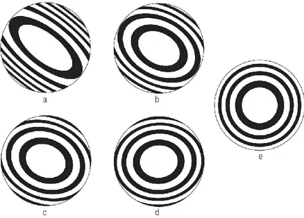
Errors in the alignment of an OAP can be of 3 types: focus & tilt, incorrect setting of off-axis distance and rotational mis-alignment. All these errors give different patterns on the interferogram.
Focus and tilt are easily recognizable, as they give circular or elliptical fringes in case of focus and straight fringes in case of tilt.
When the off-axis distance is set incorrectly, a comatic error will appear, but since the OAP is an off-axis section of a symmetric parabola, this error will appear as astigmatism, at least for small mis-alignments.
An incorrect rotation of the OAP around its mechanical center will give again errors of comatic nature, but the direction of coma is rotated with respect to the tangential plane (i.e., the fringes are inclined with respect to the tangential plane). The OAP1 will be deliberately defocused in order to see in the interferogram the typical elliptical/circular fringes due to defocus. The OAP is then aligned by minimizing the rotation of the fringe pattern with respect to the tangential plane and reducing the ellipticity of the fringe pattern.
When properly aligned, AOP1 will produce a collimated beam and an image of the pupil on the DM, which is the second optical element to be installed on the the optical bench.
Figure 3: a sketch of the starting alignment setup. Light from laser can be inserted in the optical path simply deploying a flat folding mirror.
Proc. of SPIE Vol. 10702 107024C-5 Downloaded From: https://www.spiedigitallibrary.org/conference-proceedings-of-spie on 20 Nov 2020
b
e
Figure 4: fringe patterns for different mis-alignments of the OAP. Panel e is an aligned OAP out of focus.
The DM in this phase is treated as a simple flat mirror, as functionality tests will be performed in advance on a separate test bench, aiming also to test the communication between the DM and the CRED2 camera.
OAP2 will be aligned following the same procedure used for OAP1, with the only difference being in the reference setup mirror. Since OAP2 will deliver a focusing beam, the reference mirror will be spherical.
The couple OAP3-OAP4 will be aligned using the same approach.
Once the alignment of the reflective elements will be completed, it is time for the alignment of the masks for coronagraphy.
We recall here that we have apodizers at 50 mm from the pupil plane, occulters in the focal plane and Lyot stops in a second pupil plane. Since many masks are in pupil planes or very close to it, the PRI lens will be aligned before, in order to produce an image of the pupil (and thus of the masks in the pupil planes) when deployed. This lens is aligned in Ti-Tilt and Decenter using back reflection from the laser and in focus using the light from the interferometer and a wedge plate.
This is a very critical part of the alignment, as any relative misalignment between apodizers, occulters and Lyot stops would translate in a contrast loss in the coronagraphic performance. The idea is to align one coronagraph at the time, starting from the apodization mask, then the Lyot stop and finally the occulter mask. When the first set of 3 masks is aligned, the wheels are rotated of one position and the next set of 3 masks is aligned.
The tolerance on the absolute position and orientation of the mask is not critical. The fine centering of the scientific beam on the masks at the telescope can be done steering our 2 internal tip-tilt mirrors. A different orientation of the masks with respect to the real telescope spider orientation can be compensated rotating the bearing when at the telescope. However, the relative positioning and orientation between the coronagraphic masks is a much more sensitive issue, as a small misalignment between different masks immediately affects the contrast.
The alignment of the masks in the pupil planes is performed deploying the PRI and illuminating the masks with the interferometer light, recording the image of the mask on the detector in the scientific focal plane.
The occulting masks are imaged on the same focal plane using the light from the integrating sphere.
As described before, the most important issue is the mutual alignment of the masks of every coronagraph. The shaped pupil is the most complicated, being the only one using apodizing masks and the only one with no circular symmetry. An example of mutual alignment of an apodizer-occulting mask is depicted in Figure 6 & Figure 7.
Finally, the last critical element to be aligned are the ADC prisms. The ADC is inserted as last element in the optical path because, for its nature, it would change the direction of propagation of any wavelength but the 1.33 μm. The light sources used for the alignment are based on He-Ne laser (632.8 nm) or broadband visible light, thus the light would pass deviated from the ADC. When the ADC is set for minimum dispersion, monochromatic light would pass with the same
Proc. of SPIE Vol. 10702 107024C-6 Downloaded From: https://www.spiedigitallibrary.org/conference-proceedings-of-spie on 20 Nov 2020
angle of propagation but rigidly shifted. The mutual rotation of the two prisms of the ADC is set comparing the lateral displacement of the transmitted He-Ne beam with the expectation from a Zemax analysis.
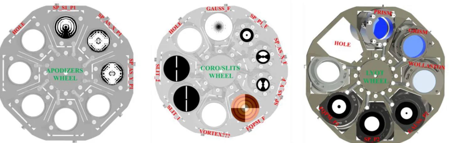
Figure 5: the 3 wheels containing, from left to right: apodizers, occulters and Lyot stops. A total of 3 apodizers, 5 occulters and 3 Lyot stops, allowing to perform 3 different coronagraphic techniques are currently in the design.
Figure 6: example of the alignment for one of the apodizing masks of the shaped pupil coronagraph. The mask is initially decentered and rotated wrt its nominal position. The mask is then centered, fitting a circle whose centroid represent the geometrical center of the mask and making it coincident with the reference centroid on a CCD of scientific focal plane defined during the alignment of the optical path. Two suitable symmetric features are then identified on the mask and the orientation of the mask is adjusted to have these features in nominal position accordingly to simulations and Zemax model. If the features cannot be positioned on their nominal positions at the same time, the mask is tilted wrt the beam. Tilt can be adjusted with shims.
Proc. of SPIE Vol. 10702 107024C-7 Downloaded From: https://www.spiedigitallibrary.org/conference-proceedings-of-spie on 20 Nov 2020
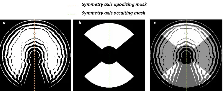
Figure 7: example of alignment of one of the asymmetric occulting masks. An apodizing mask is shown in panel a, the red dashed line represents its symmetry axis. Its position on the CCD on the scientific focal plane will be defined identifying the geometric center of the image and two symmetric features. The imaginary line passing through the geometric center of the mask image at half of the distance between the two features is the symmetry axis. In panel b an asymmetric occulting mask is shown. The occulter is first centered on the apodizer geometric center and then correctly rotated in order to have the mask’s transmission borders symmetric to the symmetry axis of the apodizer previously identified. This means that now the symmetry axes of apodizers and occulters are coincident, as shown in panel c.
4. CURRENT STATUS
At the time of writing, SHARK-NIR is at level of sub-system tests, as most of the optical elements have been received and are being tested, when necessary, at OAPD. One of the crucial elements in the design is the DM, used for the NCPA and residual telescope jitter compensation. The DM will operate in synergy with the CRED-2 camera from First Light, where the residual jitter of the telescope not compensated by FLAO will be analyzed acquiring images from the on-axis star at a high framerate (up to 6 KHz, with the peak frequency of the DM being 2 KHz).
The communication between these two elements will occur through a Real Time Computer (RTC) from Microgate. In order to test the communication before installing these two crucial elements onto the SHARK-NIR bench, we developed a test bench including both the DM and CRED-2. To maximize the reliability of the test results obtained on this bench, we illuminate the DM with a beam of the same diameter as in the final instrument and we have the same F# of the beam on CRED-2.
The test bench has two additional channel, one to monitor at lower framerate but higher SNR the stability of the spot centroid during a fast tip-tilt correction and one, making use of a commercial Shack-Hartmann WFS, to verify that the static aberrations imposed to the DM are maintained during the fast tip-tilt correction. We recall that the DM will be in charge also of removing the NCPA, and thus its shape during scientific observations will not be, very likely, its best flat but a different shape. This shape must be maintained during the correction of residual jitter.
Since the Shack-Hartmann WFS and also the slow frame rate camera are not sensitive to NIR, while CRED-2 is not sensitive to visible light, the bench has two different light sources, co-aligned, to feed the relative channels. A He-Ne laser for Shack-Hartmann and low frame rate camera and a NIR lamp, whose luminous output is tunable so to test the setup at different SNRs, for the CRED-2.
The bench is currently at Microgate for the optimization of the parameters of the RTC.
In the first phases of the SHARK-NIR optical bench alignment, the DM will be replaced by a dummy flat mirror provided by ALPAO, with exactly the same mechanical layout of the DM.
Proc. of SPIE Vol. 10702 107024C-8 Downloaded From: https://www.spiedigitallibrary.org/conference-proceedings-of-spie on 20 Nov 2020
5. CONCLUSIONS
SHARK-NIR is a compact design coronagraphic camera with low resolution spectral capabilities, having as a main scientific target the direct imaging of exo-planets. This requires an exquisite performance both in terms of wavefront error and jitter compensation and in terms of star light suppression. Theoretical performance derived from simulations [5] give a contrast up to 10-6, depending on the seeing conditions, coronagraphic technique and data reduction analysis,
making it, when in operations, the most sensitive coronagraph in the Northern hemisphere.
The achievement of such a performance is strictly related to the accuracy and quality of the optics and their alignment. We thus devised testing of all the optical components of the instrument, some required directly to the provider and some performed at OAPD, and an alignment procedure using both a laser beam for gross alignment and an interferometric beam to achieve the required tolerances.
The AIV phase of the instrument started recently, testing the optical quality of the optical components already at OAPD and the adjustment precision of the mechanical mounts of the mirrors, and it will continue for the next year, in order to have the instrument operative at the telescope in 2020.
REFERENCES
[1] J.Farinato et al., “SHARK-NIR Channel: a high contrast imager with coronographic capabilities for the Large Binocular Telescope”, J. Mod. Opt. 43, 289-293, 1996
[2] J.Farinato et al., “The NIR arm of SHARK: System for coronagraphy with High-order Adaptive Optics from R to K bands”, International Journal of Astrobiology 14 (3), 365–373, 2015
Proc. of SPIE Vol. 10702 107024C-9 Downloaded From: https://www.spiedigitallibrary.org/conference-proceedings-of-spie on 20 Nov 2020
[3] D.Vassallo et al., “Validating the phase diversity approach for sensing NCPA in SHARK-NIR, the second-generation high-contrast imager for the Large Binocular Telescope”, in Proc.SPIE, (this conference)
[4] V.Viotto et al., “SHARK-NIR system design analysis overview”, Proc. SPIE Vol. 9911, 991127, 2016
[5] E.Carolo et al., “SHARK-NIR coronagraphic simulations: performance depending on the Strehl Ratio”, in Proc. SPIE, (this conference)
Proc. of SPIE Vol. 10702 107024C-10 Downloaded From: https://www.spiedigitallibrary.org/conference-proceedings-of-spie on 20 Nov 2020