www.small-journal.com
Reversible Cavitation-Induced Junctional Opening
in an Artificial Endothelial Layer
Giulia Silvani, Chiara Scognamiglio, Davide Caprini, Luca Marino, Mauro Chinappi,
Giorgia Sinibaldi, Giovanna Peruzzi, Mohammad F. Kiani, and Carlo M. Casciola*
G. Silvani, Prof. L. Marino, Dr. G. Sinibaldi, Prof. C. M. Casciola Department of Mechanical and Aerospace Engineering Sapienza University of Rome
Via Eudossiana 18, 00184 Rome, Italy E-mail: [email protected]
G. Silvani, Dr. C. Scognamiglio, Dr. D. Caprini, Dr. G. Peruzzi, Prof. C. M. Casciola
Center for Life Nano Science Istituto Italiano di Tecnologia
Viale Regina Elena 291, 00161 Rome, Italy Prof. M. Chinappi
Department of Industrial Engineering Università di Roma Tor Vergata Via del Politecnico 1, 00133 Rome, Italy Prof. M. F. Kiani
Department of Mechanical Engineering College of Engineering
Temple University
Philadelphia, PA 19122, USA
The ORCID identification number(s) for the author(s) of this article can be found under https://doi.org/10.1002/smll.201905375.
DOI: 10.1002/smll.201905375
otherwise inaccessible regions. Neverthe-less, local uptake at the target requires drugs diffusion across the endothelial barrier lining the blood vessel walls and through the surrounding tissue.[1,2]
The endothelial layer is a tissue formed by a tessellation of specialized cells tight-ened together by a system of protein com-plexes, called interendothelial junctions. Two different transport pathways are known, namely the transcellular pathway implying molecule transport through the cellular membrane and the paracel-lular pathway where the passage occurs between adjacent cells.[3] The central bio-logical structure in transmembrane trans-port is the cellular membrane, consisting of a lipid bilayer, where the hydrophilic lipid heads are exposed to the aqueous environments of the cytoplasm from one side and the extracellular matrix on the other, with the hydrophobic hydrocarbon tails sandwiched in the intraleaflet space. Concerning the paracellular pathway, the crucial elements are protein complexes known as junctions, which tight together neighboring endothelial cells. The junctions allow or deny transit of molecules depending on size and charge through a tightly regulated process.[3] Among others, adherent junctions comprise vascular endothelial cadherin (VE-cadherin), a protein responsible for vessel permeability and endothelial integrity.[4–6] This particular junction protein is clustered at cell–cell contacts and anchors to the actin cytoskeleton to form a dynamic pro-tein complex the configuration of which rapidly adapts to the functional state of the cell.[7,8] Thanks to the fast response of the junctions to external stimuli, drug delivery may be coordinated by a suitably tuned mechanical actions able to induce their dynamic opening and closure which gives rise to a reversible interruption of the endothelial layer continuity.[9,10]
A crucial issue in controlled drug delivery is the assess-ment of the biological effects induced by the external stimuli aimed at facilitating drug passage, which is especially difficult to achieve in vivo. Microfluidic systems provide the opportunity to manipulate fluids at the micrometer scale and to perform analysis under precise and reproducible conditions,[11] allowing for well controlled experiments that can be exploited to improve drug delivery efficiency and understand the underlying trans-port mechanisms.[12–14] These systems have been used in different fields of biology and medicine, including development
Targeting pharmaceuticals through the endothelial barrier is crucial for drug delivery. In this context, cavitation-assisted permeation shows promise for effective and reversible opening of intercellular junctions. A vessel-on-a-chip is exploited to investigate and quantify the effect of ultrasound-excited microbubbles—stable cavitation—on endothelial integrity. In the vessel-on-a-chip, the endothelial cells form a complete lumen under physiological shear stress, resulting in intercellular junctions that exhibit barrier functionality. Immunofluorescence microscopy is exploited to monitor vascular integrity following vascular endothelial cadherin staining. It is shown that microbubbles amplify the ultrasound effect, leading to the formation of interendothelial gaps that cause barrier permeabilization. The total gap area significantly increases with pressure amplitude compared to the control. Gap opening is fully reversible with gap area distribution returning to the control levels 45 min after insonication. The proposed integrated platform allows for precise and repeatable in vitro measurements of cavitation-enhanced endothelium permeability and shows potential for validating irradiation protocols for in vivo applications.
1. Introduction
In drug delivery, therapeutic agents are most often injected sys-temically in the circulation which is a preferred route to reach
of drug carriers,[15–17] point-of-care diagnostics,[18] and organs-on-a-chips.[19–21] Organs-on-a-chips can be designed to incor-porate the appropriate biophysical stimuli and can accelerate pre-clinical drug screening. In this way cost/time for new drug development can in principle be saved, minimizing the risk for the patient[22] and partially avoiding ethical issues related to in vivo studies.[23]
In particular, an in vitro microvasculature, designed to mimic vascular geometry and to reproduce the appropriate range of hydrodynamic forces, e.g., shear stress, will provide a significant advancement in drug delivery studies. Artificial vascular systems have been used for studying different drug delivery protocols, including engineered drug carriers,[24–26] electroporation,[27] and acoustic mediated delivery and release.[2,28] Cavitation is an especially promising technique for facilitating drug delivery.[29,30] In this context, it can be defined as the dynamics of a population of microbubbles (MBs) stimulated into motion by ultrasound (US) which results in a localized mechanical action.[31] The bubbles may be naturally present/nucleated in the tissue or may be introduced by injec-tion. In the latter case the preferential administration route is intravenous.
Experimental findings show that the application of high intensity US may result in transient cavitation, including bubble nucleation, expansion, collapse, and subsequent shock waves.[32] Theoretical models of lipid bilayers[33] focus the atten-tion on the hydrophobic chains forming the inner layer between the two membrane leaflets which may host dissolved gas. Under the negative pressure due to US excitation, gas pockets may form in the intraleaflet space nucleating MBs. Their sub-sequent expansion would lead to membrane permeabilization by mechanically forcing the bilayer structure and the junctions holding together the endothelium. The model may explain why relatively moderate US excitation is able to induce significant bioeffects. However, when pre-existing MBs are injected before sonication, the required acoustic power level is substantially reduced and the effect is restricted in more controllable way to the vasculature. In this way, adverse bioeffects, i.e., ischemic, apoptotic areas, or bleeding are mitigated.[34]
Externally injected MBs, typically lipid shells encapsu-lating a heavy molecular weight inert gas,[35] were originally introduced and are still used clinically as contrast agent in US imaging.[36,37] More recently, they have been proposed for therapeutic applications, drug delivery in particular.[38,39] In[40,41] it was shown that the combination of US exposure and MBs is able to transiently and reversibly permeabilize the endothe-lium. Once introduced into the bloodstream and irradiated with ultrasound, MBs may oscillate (stable cavitation) or collapse (inertial cavitation). Different mechanisms may be at work to explain why MBs alter the integrity of the endothelium. In the classical view, stable MBs oscillations induce a microstreaming and related shear stress at the vessel wall that are transmitted to the junctions, while inertial cavitation leads to more intense forcing through shock wave emitted at bubble collapse and associated microjetting.[30,42] Alternatively, in the scheme intro-duced in,[33] MBs may just act as sort of local acoustic amplifiers that favor nucleation of intraleaflet nanobubbles which, in turn, deform the membrane and force the junctions. In any case, the observed result is a sequence of biological effects comprising
formation of pores into the cellular membrane and increase of intercellular distance. Bioeffects of USMB on cells and tissues are strictly related to the level of the applied acoustic pressure. At sufficiently intense irradiation level, in conditions of inertial cavitation, biological damage may follow, e.g., tissue disruption, bleeding, apoptosis, and necrosis.
As anticipated, adherent junctions comprise vascular endothelial cadherin, that exhibits a wide heterogeneity of morphologies ranging from interrupted patterns to linear, reticular, or plaque-like structures. These patterns are continu-ously reorganized by actin filament remodeling that promotes VE-cadherin clusterization at junction sites.[43] The shear stress exerted by the blood flow on the endothelial cells in the microvasculature (typically 1–12 dyn cm−2 under physiological conditions[44–46]) is crucial to achieve an endothelial phenotype characterized by streamwise cell elongation and actin-mediated stabilization of junction proteins. Under low flow rate, VE-cadherin forms an irregular overlapping network. At high flow rate, actin drives VE-cadherin remodeling into an overall linear pattern strengthening the barrier function.[6,47]
Formation of stable junctions is not sufficient for a functional endothelium. In fact, a proper shear stress is also needed for cell adhesion to the substrate.[48] In artificial, microfabricated blood vessels, wall functionalization by the extracellular matrix protein fibronectin is crucial to bind the endothelial cell basal layer to the underlying substrate via focal adhesions, namely the subcellular structures devoted to anchor the endothelial cells.[49] In presence of fibronectin coating, a sufficiently intense shear stress is also known to promote focal adhesions, leading to an overall confluent and well attached endothelium.[50]
US irradiation of MBs shows great potential for endothelium permeabilization, hence the growing interest for basic studies aimed at quantifying the effect of the irradiation on endothelial barrier function. The application of USMB in mimetic in vitro systems is therefore a valuable alternative to in vivo animal models. Current in vitro models of the endothelial barrier comprise permeable membranes covered with an endothelial monolayer immersed in liquid tanks where MBs are injected and irradiated by US.[51,52] Alternatively, tissue phantom models consisting of an agarose-gel tissue platform optimized to hold the bubble suspension are used to study tissue-like response to USMB irradiation.[53] While these devices have significantly contributed to our understanding of cavitation in tissues, they are limited by the lack of physiological flow conditions and appropriate vessel geometry which, as explained above, are crucial to achieve a functional endothelial barrier.
Recently, a relatively simple and effective microfluidic network has been proposed[54] which mimics the in vivo vas-cular system allowing for complete lumen formation under physiological flow conditions. This system has been used to mimic the blood–brain barrier (BBB) and characterize its permeability[54] or study the signaling pathway in neuroin-flammation during sepsis.[55] In the present paper, we use this system to characterize cavitation-enhanced endothelium per-meability. Human umbilical vein endothelial cells (HUVECs) are cultured to form complete lumens lining two independent microchannels encircling an inner tissue chamber, see the Experimental Section below. Microchannels and tissue chamber are connected through a membrane endowed with
micrometer size pores. MBs are injected into the channels and are irradiated by low intensity US (0.4 and 0.72 MPa) at 1 MHz to force stable acoustic cavitation. In the same conditions (SonoVue microbubbles, irradiated at 1 MHz, with pulse length (PL) = 500 µs, pulse repetition frequency (PRF) = 20 Hz, total pulse number 600, fluid speed of 0.83 mm s−1) the threshold for inertial cavitation is 0.86 MPa. In fact, the inertial cavita-tion threshold depends on a number of factors,[56] e.g., pressure amplitude, excitation frequency, PL, and PRF. The bubble con-vection speed also matters, since in an intermediate excitation range the inertial response is transient and strongly depleted after the first pulse. As a consequence, the threshold for fully inertial cavitation increases at decreasing convection speed. In the present case, the low fluid speed of 0.83 mm s−1 raises the threshold at 0.86 MPa,[56] as anticipated.
The effect on the endothelium is identified by immunofluo-rescence staining of junctions and actin filaments to detect the induced morphological changes. The efficacy of US, with and without MBs, is monitored and quantified in a highly reproduc-ible fashion at different stages of the irradiation process. The endothelial layer integrity recovery under different irradiation protocols is finally assessed.
2. Results
2.1. Vessel-on-a-Chip Characterization
The vascular channel in our system is illustrated in Figure 1A showing a composite brightfield picture of the endothelium
reconstructed from several high resolution images (20× magnification, 1940 × 1460 px). A uniform endothelial layer forms a complete lumen in the channel with individual cells elongated in the direction of flow from left to right. Confocal fluorescence images of cell nuclei stained with 4′,6-diamidino-2-phenylindole (DAPI) show that the cells completely line the vessel walls, Figure 1B–D corresponding to three planes at the bottom, middle (note that cells are in this case present only on the side walls) and top of the channel, respectively. Staining with Calcein, a cell-permeant dye, confirms cell viability (data not shown). This analysis validates that a uniform, 3D endothelial barrier is formed throughout the channel section, reproducing and resembling the structure of a physiological capillary vessel.
2.2. Endothelium Maturation
The maturation of a confluent HUVEC layer, namely the cob-blestone phenotype with established barrier function,[57] is confirmed by immunofluorescence microscopy at different cul-ture stages and flow rates. A complete HUVEC layer is obtained after a 3-day on-chip culture and is characterized using immu-nolabeling visualization of VE-cadherin protein and of actin filaments. A crucial feature for endothelial cell shape main-tenance, movement, and vascular integrity is the effective anchorage of VE-cadherin to the cytoskeleton.[5] Endothelial cells sense the applied shear force and respond by remodeling the cytoskeleton[8] which, in turn, alters the tension forces on the junction proteins in a time-dependent manner.
Figure 1. Vessel-on-a-chip. A) Brightfield image of HUVECs seeded in the vascular channel. The inset highlights the elongation of cells in the direction
of flow. B–D) Fluorescence images of cell nuclei shown after DAPI staining. Top (panel B), middle (panel C), and bottom (panel D) sections of the vascular channel. In panel (B) and (D), the nuclei of the cells in the top and bottom channel wall are visible. The nuclei focused in panel (C) belongs to cells adhered on the lateral walls of the channel.
During the 3-day culture, cells were first exposed to a 24-hour ramp up flow followed by a 2-day exposure to a con-tinuous low (0.5 µL min−1) or high (25 µL min−1) flow rate. In order to obtain a compact endothelium the initial cell den-sity is crucial (60–70% confluence optimized for HUVECs). During maturation, the endothelium structure develops from an initial disorganized configuration to compact endothelial layers (90–95% confluence); see Figure 2A,B, obtained under 25 and 0.5 µL min−1 flow, respectively corresponding to 10 and 0.2 dyn cm−2.
During the initial phase cells grow and tend to connect to each other through the plasma membrane. The process is par-ticularly evident in subconfluent conditions, see Section SM1 in the Supporting Information. The process requires actin filament remodeling as highlighted by the numerous stress fibers traversing the cytoplasm (center panel in Figure SM1 in the Supporting Information). In these conditions, cells are apparently larger and their perimeter is longer than under con-fluent conditions (left panel of Figure SM1 in the Supporting Information). The VE-cadherin pattern is discontinuous and formed by multiple short linear elements connected to stress fibers and projecting normally from the cell border toward the neighboring one (right panel of Figure SM1 in the Supporting Information). Once cell contact is achieved, the actin-driven VE-cadherin clusterization takes place, providing a well estab-lished, resting confluent state (Figure 2A) when cells acquire a polygonal shape while reducing the junction perimeter. At this stage, VE-cadherin is well localized at the cell periphery, as expected of a tight cobblestone monolayer.[57] The VE-cadherin pattern becomes linear and well packed, with evident reticular networks (see the arrow in the right panel in Figure 2A). Along the process, actin reorganizes into cortical filaments aligned with the junctions with no stress fiber inside the plasma mem-brane (center panel in Figure 2A). Under this condition, vas-cular stability—, e.g., contact inhibition of growth, endothelial
integrity and reduced loss of cells—was observed as discussed in.[58]
A similar mature endothelial layer was also obtained at low flow rate (0.5 µL min−1, corresponding to a 0.2 dyn cm−2 shear stress). In this almost static condition, partial vessel wall detachment from the microfluidic channel is often observed (see the left panel of Figure 2B where the endothelium miss to perfectly follow the microchannel profile), presumably due to lack of focal adhesion expression.
2.3. Bubbles Injection and US Exposure
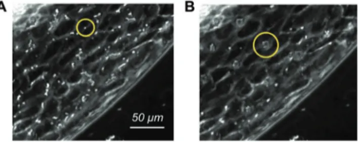
After endothelium maturation, the microfluidic chip is trans-ferred to the insonication chamber described in the Experi-mental Section which is placed on the microscope stage. MBs (Sonovue) are then injected in the vascular channels and activated by US. The insonication protocol consists of a sequence of bursts at 1 MHz formed by 500 cycles repeated every 50 ms for a total duration of 30 s with 0.1% duty cycle (DC). As the bubble residence time over a region of the endothelium matters when it comes to the bioeffects induced under insonication, the perfusion rate is transiently reduced to 1 µL min−1 upon US exposure. Slowing down the flow results in a more faithful reproduction of the bubbles dynamics in capillaries, where the convective velocity is in the range 0.5–1.5 mm s−1.[59] Under such mild flow the acoustic forces acting on the bubbles are sufficient to temporarily keep the bub-bles at rest with respect to the endothelium. MBs distribute homogeneously along the channel and tend to approach the upper endothelial wall, due to buoyancy, Figure 3A. Time-lapse imaging reveals that US radiation forces slow down the MBs initially and eventually lead to their agglomeration, resulting in evenly spaced bubble clusters[60] (see yellow circles in Figure 3B and the video SM2 in the Supporting Information). Figure 2. Endothelium maturation. Confocal fluorescence images of the endothelium at 90–95% confluence at different flow rate. A) Physiological flow
rate (25 µL min−1). B) Flow rate: 0.5 µL min−1. Left column: overlay of fluorescence images showing cell nuclei (blue, DAPI), actin filaments (green, PhalloidinAtto488), cell junctions (red, VE-cadherin). Middle column: inset showing stress fibers (actin filaments). Right column: inset showing cell junctions (VE-cadherin).
The effect of the convection velocity has been explored in dedi-cated experiments where the flow rate was changed in the range 1–25 µL min−1. The data shown in Figure SM3 in the Supporting Information confirm that the desired bioeffect is obtained at the smaller flow rates while at 25 µL min−1 the MB residence time is apparently insufficient.
2.4. Bioeffects and Data Analysis
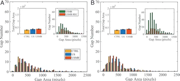
Modification of the intercellular junctions induced by US (at 0.4 and 0.72 MPa radiation pressure), with and without MBs, is evaluated by image analysis of VE-cadherin. The image anal-ysis, the Experimental Section, consists of identifying the gaps present in the endothelial layer, quantifying their area in terms of pixels (1 pixel = 0.22 × 0.22 µm2 in our imaging system) and number. Figure 4A shows the image of a vascular channel used as control with the main features already discussed in Section 2.2. Intercellular gaps for samples irradiated with US at 0.72 MPa pressure with no MBs and with MBs, respectively, are shown in Figure 4B,C. VE-cadherin was stained within 4 min
after the end of irradiation to allow time to extract the sample from the insonication chamber and inject paraformaldehyde (PFA) (see the Experimental Section) into the vascular channels under the biological hood.
The acoustic radiation forces, either acting directly on the cells, Figure 4B, or combined with the oscillating MBs, Figure 4C, induce local disruptions of cell–cell contacts (exam-ples highlighted by arrows) that are identified by VE-cadherin reorganization. The number of intercellular gaps and their areas, obtained by image postprocessing (see the Experimental Section), are plotted in Figure 5A,B for vascular channels irradi-ated at 0.4 and 0.72 MPa, respectively. The histograms show the area distributions for control, US and USMB samples, each of them obtained after averaging over three experiments. From the Figure 3. Brightfield images showing a portion of the vascular channel
with injected microbubbles. A) MBs transported by the flow before irradiation. B) MB cluster formed under US-induced radiation forces. The yellow circles highlight a single bubble (A) and a cluster (B), respectively.
Figure 4. Confocal fluorescence images of VE-cadherin showing a region
of confluent endothelium cultured at 25 µL min−1. A) Untreated sample (CTRL). B) Ultrasound irradiated sample (US). C) Bubble injected ultrasound irradiated sample (USMB). Acoustic pressure 0.72 MPa corresponding to piezo driving voltage of 140 mV. Irradiation protocol: duration 30 s, 500 cycles, frequency 1 MHz. Arrows highlight typical intercellular openings.
0 500 1000 1500 2000 2500
Gap Area (pixels)
0 10 20 30 40 50 60 70 Gap Number
Total Gap Area
CTRL US USMB
CTRL US USMB
0 500 1000 1500 2000
Gap Area (pixels)
10 20 30 40 50 60 70 Gap Number
Total Gap Area
CTRL US USMB 0 1 2 105 0 1 2 105
A
B
**
***
Figure 5. Junction opening. Number of gaps versus gap area. Comparison between untreated samples (CTRL), ultrasound irradiated samples (US), and
bubble injected ultrasound irradiated samples (USMB). Area expressed in pixel where 1 pixel = 0.225 × 0.225 µm2. A) Irradiation pressure: 0.4 MPa. B) Irradiation pressure: 0.72 MPa. Same irradiation protocol as in Figure 3. The insets report for each case the total gap area over the entire vascular channel. Asterisks are reported for cases with statistical significance: ** CTRL versus US: p = 0.0053, *** CTRL versus USMB: p = 0.0004, and US versus USMB: p = 0.0007.
histograms, the main effect of US and USMB is the increase of the number of gaps, as shown by the shape of the distribution which, to a first approximation, is almost unaltered with respect to the control. The total gap area is illustrated in the insets. These findings indicate that US alone at the lower acoustic pressure, 0.4 MPa, has no substantial effect on the endothe-lium integrity. Acoustic pressure increase of 0.72 MPa leads to a significant total gap area increase. The overall effect ampli-fies dramatically in presence of MBs, with the total gap area growing mildly over the US alone case at 0.4 MPa, to become 130% at 0.72 MPa. The increase of USMB total gap area is significant as compared with the control case, for 0.72 MPa, i.e., 360%. Although much smaller, it is also observed at 0.4 MPa, see the error bars reported in the inset.
Endothelium integrity recovery 45 min after the end of the irradiation protocol is evaluated by staining the irradiated sam-ples exposed to the physiological shear stress of 10 dyn cm−2. As shown in Figure 6A,B for 0.4 and 0.72 MPa irradiation pres-sure, respectively, endothelium integrity is completely recov-ered, with gap area distributions returning to control values, and with no significant difference between US and USMB values for both pressures, indicating that the opened inter-cellular spaces do close back after irradiation. The total gap area measured after 45 min reproduces that of the untreated vascular channels (insets on the left of Figure 6A,B). The two insets on the right of Figure 6A,B provide the comparison of gap area distributions for USMB just after irradiation and after 45 min recovery. Apparently, during recovery the large number of relatively small gaps formed by cavitation close entirely. Data collected after 15 min from US exposure indicates that the closure of gaps is not concluded yet, suggesting that the recovery is still in progress and entirely complete within 45 min, see Figure SM4 in the Supporting Information.
Figure 7 shows the same data of Figures 5 and 6 rear-ranged to allow for direct appreciation of the pressure ampli-tude effect. Figure 7A shows gap areas for the two USMB cases
(0.4 and 0.72 MPa) immediately after irradiation compared to the control.
With increasing irradiation pressure, the shape of the distri-bution is substantially unaltered, apart from a slight shift of the distribution towards larger gaps, with the probability density function (pdf) at both 0.72 and 0.4 MPa reproducing the shape of the control (lower inset of Figure 7A,B). As already discussed in Figure 5, the total gap area is greatly increased over the con-trol for the irradiation of 0.72 MPa. The difference is smaller, though appreciable with the available statistical accuracy, for 0.4 MPa.
As shown in Figure 7B, 45 min after irradiation, total gap area returns to control for both pressure amplitudes. Within statistical accuracy, the gap area histograms reproduce the control, demonstrating the endothelium integrity recovery for both cases.
As discussed in Section 2.2, endothelium maturation under appropriate shear stress (physiological 1–12 dyn cm−2[37–39]) is crucial to achieve a physiological barrier. Figure 8A highlights the effect of cavitation on an unstable endothelium cultured at a flow rate of 0.5 µL min−1 (shear stress of 0.2 dyn cm−2). The figure shows the gap area distribution for the control case, under simple US irradiation and when irradiation is applied in presence of MBs. The comparison of the untreated sam-ples with those cultured at physiological shear stress indicates that the endothelium morphology is substantially the same (leftmost inset). Also the gap area distribution for the irradi-ated endothelium with no MBs is substantially similar to that found at physiological shear stress (middle inset) with gap number and total gap area slightly larger. The rightmost inset, however, demonstrates that irradiated MBs produce a substan-tially larger effect on the endothelium cultured under almost static conditions with considerable increase of the gap number with respect to endothelium cultured under physiologically rel-evant flow conditions. Figure 8B shows the fluorescence image of gaps formed in the endothelium cultured at 0.5 µL min−1
0 500 1000 1500 2000 2500
Gap Area (pixels)
0 10 20 30 40 50 60 70 Gap Number CTRL US USMB
Total Gap Area
Gap Number
Gap Area (pixels) CTRL US USMB
0 500 1000 1500 2000 2500
Gap Area (pixels)
0 10 20 30 40 50 60 70 Gap Number CTRL US USMB
Total Gap Area
Gap Area (pixels)
Gap Number 0 0.5 1 1.5 2 105 0 0.5 1 1.5 2 105 0 500 1000 1500 0 20 40 60 0 500 1000 1500 0 20 40 60 USMB USMB REC
A
B
Figure 6. Junction recovery. Number of gaps versus gap area 45 min after US irradiation. Comparison between untreated samples (CTRL), ultrasound
irradiated samples (US), and bubble injected ultrasound irradiated samples (USMB). A) Irradiation pressure: 0.4 MPa. B) Irradiation pressure: 0.72 MPa. In each panel, the inset at the top left reports the total gap area in pixels. The inset at the top right compares data immediately after irradiation (same as Figure 5) and 45 min later.
after MBs irradiation. These findings indicate that the unstable endothelium obtained with low flow rate culture condition is more prone to gap formation, particularly in presence of MBs. In other words, the sensitivity of the endothelium to US irra-diation and MB cavitation is significantly dependent on the culture conditions. This observation is consistent with our find-ings presented in Section 2.2, where the appropriate flow rate is found crucial also for the proper adhesion of endothelial cells to the substrate.
3. Conclusions
A vessel-on-a-chip reproducing the physiological features of actual microvasculature is exploited to quantify the effect of
stable cavitation on the reversible opening of intercellular junctions. The flow-induced shear stress on the endothelium cultured inside the microfluidic device is found to crucially affect the intercellular junction strength, with the physiological level of shear stress determining the morphology of adherent junctions and actin cytoskeleton. VE-cadherin staining was used to investigate the response of the junctions to US and to MB cavitation. Although US alone is able to open gaps in the mature endothelium, the presence of MBs excited by US at resonance conditions largely increases gap number, with the total gap area increasing by 360% of that found in the intact endothelium. Interestingly, the gap area distribution seems to be quite insensitive to the magnitude of irradiation. The forma-tion of gaps under US irradiaforma-tion depends on the culture condi-tions, with gap number and total area increasing for endothelia
0 500 1000 1500 2000 2500
Gap Area (pixels)
0 10 20 30 40 50 60 70 Gap Number
Total Gap Area
CTRL USMB 0.40 MPaUSMB 0.72 MPa
Gap Area pd f CTRL USMB 0.40 MPa USMB 0.72 MPa 0 0.5 1 1.5 2 105 0 500 1000 1500 2000 2500
Gap Area (pixels)
0 10 20 30 40 50 60 70 Gap Number
Total Gap Area
Gap Area pd f USMB 0.40 MPa CTRL USMB 0.72 MPa CTRL
USMB 0.40 MPa REC USMB 0.72 MPa REC
0 0.5 1 1.5 2 10 5 0 500 1000 1500 0 0.1 0.2 0.3 0.4 0 500 1000 1500 0 0.1 0.2 0.3 0.4
A
***
**
B
Figure 7. Effect of irradiation pressure on junction opening. Number of gaps versus gap area. Data taken immediately after A) irradiation and B) 45 min
after irradiation. Bubble-injected ultrasound-irradiated samples (USMB) at pressure 0.4 and 0.72 MPa. The upper and lower inset provides the total gap area and gap area probability density function, respectively. Asterisks are reported for cases with statistical significance: ** USMB 0.40 MPa versus USMB 0.72 MPa, p = 0.0074; *** CTRL versus USMB 0.72 MPa, p = 0.0004.
0 500 1000 1500 2000 2500
Gap Area (pixels)
0 20 40 60 80 100 120Gap Number
Gap NumberGap Area (pixels) Gap Area (pixels) Gap Area (pixels) CTRL US USMB 0 500 1000 1500 0 50 100 CTRL 0.5 l/min CTRL 25 l/min 0 500 1000 1500 0 50 100 US 0.5 l/min US 25 l/min 0 500 1000 1500 0 50 100 USMB 0.5 l/min USMB 25 l/min
A
Figure 8. Endothelium cultured at 0.5 µL min−1. A) Gap area histogram comparison between US alone and USMB. MBs are injected at the flow rate of 1 µL min−1. The insets compare this flow rate with the physiological one (25 µL min−1) for the control case (left), US alone (middle), and US irradiated MBs (right). B) VE-cadherin confocal fluorescence image of a portion of endothelium after US exposure in presence of MBs.
cultured at shear stress lower than the physiological value. Endothelium cultured under insufficient shear stress intensity is prone to instability and tends to detach from the substrate entailing vessel collapse, presumably induced by lack of focal adhesions. A central finding is that the effect of stable MBs cavitation is transient and reversible since in all the cases we investigated the endothelial barrier reverts to the original state after removing US irradiation.
The proposed platform combining the vessel-on-a-chip with controlled MBs injection and US irradiation provides a new and original methodology for the quantitive understanding of cavitation-assisted drug delivery. The present results demon-strate how permeabilization can be achieved in controlled and reproducible conditions paving the way to new detailed studies on the physical and biological mechanisms underlaying junc-tion opening. The use of pre-existing bubbles (MB-assisted, cavitation-enhanced endothelium permeability) reduces the intensity of US irradiation thereby mitigating potential adverse bioeffects, e.g., bleeding, apoptosis, and necrosis.
From the clinical point of view, potential hazard posed by US irradiation is a crucial aspect. Although clinical protocols are not yet available, a rich literature describes promising results in this direction using in vivo models[1,61] [6,10-risposta]. In this context, an in vitro platform able to reproduce many of the aspects found in in vivo applications under strictly controlled and reproducible conditions may contribute a significant advancement of the state of the art in the field. The typical US frequency used in in vivo studies ranges from 0.3–3 MHz, the Peak Negative Pressure may vary from 0.24 to 5.3 MPa corre-sponding to a Mechanical Index of 0.2–1.9, the latter being the upper limit indicated in FDA recommendations as potentially hazardous [link]. The pulse length is typically in the order of ms and the US intensities used for delivery applications range between 0.3–3 W cm−2. Higher intensity US can be applied when the pulse length and/or pulse repetition frequency are reduced, resulting in low duty cycles. In the present case, with PL = 500 µs and DC = 0.1%, i.e., a decreased temporal average intensity, the irradiation intensity of 5 and 17 W cm−2 matches the insonication parameters indicated in in vivo protocols.
In perspective, artificial platform like the present, may even-tually help in streamlining the search for safe administration protocols in clinical application. The proposed approach could be used for preliminary assessment of potential hazards and the prevention of permanent damage to the blood vessel, not-withstanding the need of direct experimentation in vivo and the necessity of preclinical trials that remain, as yet, the conclusive safety certification. To this purpose, a dedicated experimental set up was developed to evaluate the artificial endothelial barrier tightness in different conditions (i.e., control, US excitation, USMB irradiation). The endothelial membrane permeability is quantified by measuring the diffusion of a fluo-rescent dye through the biological membrane with a time lapse acquisition under the confocal microscope, see the preliminary result described in Figure SM5 in the Supporting Information. The figure shows the time evolution over 2 h of fluorescence intensity diffused in the tissue compartment from the vascular channel across the endothelium with and without USMB appli-cation. In brief, as expected, USMB application induces an enhanced barrier permeability while US alone follows a time
history comparable to the control, suggesting that the acoustic irradiation does not damage the tissue. This approach may contribute to address potential hazard posed by US with more detailed permeability studies.
The present system, originally conceived to demonstrate the feasibility of an in vitro blood-vessel on a chip for the quantita-tive study of cavitation-enhanced endothelium permeabilization, is also open to further developments in different directions. The microdevice could be embedded within phantom tissues to reproduce the irradiation conditions of in vivo applications where high intensity focused ultrasound (HIFU) devices are used to reach inaccessible and restricted target regions deep inside the body. The microsystem could allow for addressing complete drug delivery protocols explicitly including different types of drug carriers and the interaction with a variety of tissues that can be cocultured in the central tissue chamber.
4. Experimental Section
Vessel-on-a-Chip: The vessel-on-a-chip developed in this study is based on a microfluidic device distributed by SynVivo, Inc (Huntsville, AL). The device consists of a polydimethylsiloxane (PDMS) chip (Figure 9A,B) plasma bonded to a microscope glass slide with a central tissue compartment (1575 µm width, 100 µm height) encircled by two independent vascular channels (200 µm width, 100 µm height). An interface with a series of 3 × 3 µm2, 50 µm-spaced pores along the circumference separates the vascular channels from the tissue compartment. The vascular channels were seeded with endothelial cells which, after adhesion to the substrate, mimic the 3D morphology of an in vivo microvessel.
Cell Culture: HUVECs were purchased from Lonza (Walkersville, MD, USA). The culture medium was the endothelial basal medium-2 (EBM-2) supplemented with the endothelial growth medium (EGM-2) BulletKit from Lonza (Walkersville, MD, USA). Cells were grown in tissue culture flasks and maintained in humidified atmosphere at 37 °C and 5% CO2. The culture medium was changed every 2 days and cells were used up to the 5th passage to ensure the expression of key endothelial protein components.
Cell Seeding: The protocol was used to seed the HUVECs into the microfluidic device.[54,62] Culture flasks with 80–90% HUVEC confluence were washed twice with Dulbecco Phosphate Buffered Saline (PBS) (Sigma Aldrich, Missouri, USA), detached using Trypsin-EDTA solution (Sigma-Aldrich, Missouri,USA) for 40 s at 37 °C in 5% CO2 and blocked with Trypsin inhibitor (Sigma-Aldrich, Missouri, USA). The cell suspension was collected and centrifuged at 1400 rpm for 7 min at room temperature (RT) and the supernatant was discarded. Cells were resuspended in filtered culture medium at an average concentration of 108 cells mL−1. To form an endothelial monolayer into the PDMS channels, the device was first degassed, washed with PBS and then coated with 200 µg mL−1 fibronectin (Sigma-Aldrich, Missouri,USA) at 37 °C and 5% CO2. After 2 h, the HUVEC suspension was injected into the vascular channels, using a syringe programmable pump (PhD ULTRA Syringe Pump, Harvard Apparatus, Massachusetts, USA). The input and output tubings were clamped when HUVECs reached the desired confluence (60–70%) and the device was placed in the incubator for 4 h, to let the cells attach to the channels inner walls in static condition. After incubation, the vascular channels were connected to a double syringe pump and growth medium was pulled into the channel using Tygon tubings (Saint Gobain PPL Corp., Pennsylvania, USA). To orient the cells in the flow direction, perfusion rate was ramped up to 0.5 µL min−1 over 24 h. Culture medium was then refreshed and injected into the channel at the desired flow rate (0.5 and 25 µL min−1, corresponding to a shear stress of 0.2 and 10 dyn cm−2, respectively). These flow conditions were kept for additional 2 days to achieve full junction maturation.
Immunofluorescence Staining: The state of the endothelial junctions at different stages of the experiment (i.e., maturation, ultrasound excitation, MB irradiation and eventual recovery) was assessed by fluorescence imaging following VE-cadherin protein, a crucial component of inter endothelial junctions. In addition, actin filaments rearrangement was also monitored. For staining, incubations and washings into the microchannels were performed at 0.5 µL min−1 flow rate unless otherwise stated. Cells were first washed for 30 min in PBS flow, fixed in 4% PFA for 15 min at RT in static conditions and then permeabilized for 5 min in 0.2% Triton X-100 (Sigma-Aldrich, Missouri, USA). For actin fiber organization, cells were incubated in the dark for 60 min with PhalloidinAtto488 (Sigma Aldrich) 30 µL mL−1 in PBS. To monitor cell–cell contact, HUVECs were stained with VE-cadherin mouse monoclonal antibody (ThermoFisher Scientific) at 5 µg mL−1 in 3% BSA for 1 h. Cells were then incubated in the dark with 2 µg mL−1 of AlexaFluor647 conjugate-Goat anti-Mouse IgG (H+L) Secondary Antibody (ThermoFisher Scientific) for 30 min at RT. Depending on the experiment, cells were stained before US exposure to assess endothelial maturation; immediately after US exposure to evaluate the effect on the endothelium and 45 min after US exposure to address endothelium integrity recovery under flow conditions. Nuclei were stained with DAPI (Thermo Fischer Scientific).
Microbubbles: SonoVue microbubbles (Bracco Research, Geneva, Switzerland), filled and stabilized with sulfur hexafluoride (SF6) and coated with a phospholipid monolayer shell, were used in this study. The bubbles suspension was reconstituted in 5 mL of 0.2% NaCl solution (2 × 10⁸–5 × 10⁸ microbubbles mL−1) according to the manufacturer’s instructions. The preparation was diluted to a concentration of 2 × 10⁷–5 × 10⁷ microbubbles mL−1 in culture media (plus 2.5% HEPES as buffer solution) to reach the target cell-bubble ratio (1:1).[52,63] Then, the bubble solution was injected into the vascular channel with the syringe pump. With a size ranging between 2–8 µm and a mean diameter of 2.5 µm, microbubbles were small enough to avoid vascular channel obstruction.
Ultrasound Excitation: Ultrasound bursts were generated using a signal generator, amplified by a 50-dB power gain amplifier and monitored with an oscilloscope. The amplified electrical signal was sent to an unfocused, single element, 1 MHz-center-frequency transducer with a 0.5 in (12.7 mm) diameter that transmits the US signal within a custom insonication chamber containing water. The US emitter was mounted on a dedicated support with an inclination of 45° at a distance of 35 mm from the microfluidic chip, i.e., well into the far-field where uncontrolled pressure wave variations were absent. The emitter was previously calibrated using a needle hydrophone, see Figure SM6 in the Supporting Information showing the details of the piezo calibration. To guarantee precise control over the transducer alignment, a dedicated housing was present on the insonication chamber cover lid. A sketch of the ultrasound chain is shown in Figure 9C.
Acoustical and Optical Setup: The insonication chamber filled with deionized water was positioned on a confocal microscope stage for optical observation. Phase contrast imaging was performed to monitor real-time vessel integrity and microbubble dynamics. The device was stably placed at the bottom of the chamber. Culture medium (plus 2.5% HEPES) was injected into the vascular channel at the flow rate appropriate to the specific conditions (0.5 or 25. µL min−1). The system was allowed to adapt to the new conditions for 30 min while kept at 37 °C by a PID thermal controller (Figure 9C). Cells were monitored with a time-lapse, acquiring 1 image per second with an exposure time of 300 ms.
Sonovue microbubbles were finally injected at 1, 3, 5, and 25 µL min−1 rate into the vascular channel and exposed to sine-wave bursts with 1 MHz central frequency, 500 cycles, 0.1% DC, corresponding to 500 µs Pulse Duration (PD) and 20 Hz PRF. Two different insonication conditions were realized, namely ultrasound emitted for 30 s (corresponding to 600 pulses) by the piezo-transducer driven at 80 and 140 mV, corresponding to a peak negative pressure (PNP) of 0.4 MPa (5 W cm−2 intensity level) and 0.72 MPa (17 W cm−2 intensity level), respectively. Time-lapse imaging at 10 fps with 10 ms exposure time was used to visualize bubble dynamics.
Figure 9. Vessel-on-a-chip and integrated platform for USMB irradiation. A) Sketch of the geometry showing the tissue compartment (red) surrounded
by two independent vascular channels (blue). B) Picture of the vessel-on-a-chip showing inlet and outlet tubings. C) Sketch of the ultrasound chain showing the dedicated insonication chamber, the microfluidic chip placed at the chamber bottom (enlarged view on the bottom left of the image), the thermal control to keep the biological system at 37°, the piezo-actuator generating the US at 1 MHz, and the MB injection syringe.
Image Analysis: Confocal images of different portions of the endothelium were acquired using a 20× magnification objective and successively stitched together to reconstruct the whole channel. Intercellular gaps were identified by inspection using the ImageJ software, creating a rectangular Region of Interest (ROI) enclosing the gap at its center. The channel image was then post-processed by using the list of ROIs. Image histograms within each ROI were equalized in order to increase the contrast and better identify the gap. Binarization was then obtained with a threshold method using the same cutoff value for all ROIs. The gap area was then quantified counting the black pixels of the central connected blob in each binarized image. An example of ROIs with the detected gaps is reported in Figure SM7 in the Supporting Information.
Statistical Analysis: Statistical analysis was performed by unpaired t-tests, 99% confidence interval, using GraphPad Prism software. Average values of at least three independent experiments +/− SEM are shown. Comparisons between samples were considered to be statistically significant if the p-value was *p < 0.05, **p < 0.01, ***p < 0.001.
Supporting Information
Supporting Information is available from the Wiley Online Library or from the author.
Acknowledgements
This work was supported by the European Research Council under the European Union’s Seventh Framework Programme (Grant No. FP7/2007-2013)/ERC Grant Agreement No. 339446 and under the ERC-2017-PoC Grant Agreement no. 779751.
Conflict of Interest
The authors declare no conflict of interest.
Keywords
cavitation, drug delivery, endothelial junctions, permeabilization, vessel-on-a-chip
Received: September 20, 2019 Revised: October 24, 2019 Published online:
[1] S. M. Chowdhury, T. Lee, J. K. Willmann, Ultrasonics 2017, 36, 171. [2] E. Stride, C. Coussios, Nat. Rev. Phys. 2019, 1, 495.
[3] Y. Komarova, A. B. Malik, Annu. Rev. Physiol. 2010, 72, 463. [4] D. Vestweber, Arterioscler., Thromb., Vasc. Biol. 2008, 28, 223. [5] M. Giannotta, M. Trani, E. Dejana, Dev. Cell 2013, 26, 441.
[6] Y. A. Komarova, K. Kruse, D. Mehta, A. B. Malik, Circ. Res. 2017, 120, 179.
[7] A. Abu Taha, H. J. Schnittler, Cell Adhes. Migr. 2014, 8, 125. [8] Y. L. Dorland, S. Huveneers, Cell. Mol. Life Sci. 2017, 74, 279. [9] L. J. M. Juffermans, P. A. Dijmans, R. J. P. Musters, C. A. Visser,
O. Kamp, Am. J. Physiol. 2006, 291, H1595.
[10] L. J. M. Juffermans, A. van Dijk, C. A. Jongenelen, B. Drukarch, A. Reijerkerk, H. E. de Vries, O. Kamp, R. J. Musters, Ultrasound Med. Biol. 2009, 35, 1917.
[11] G. M. Whitesides, Nature 2006, 442, 368.
[12] D. A. Lavan, T. Mc Guire, R. Langer, Nat. Biotechnol. 2003, 21, 1184.
[13] I. U. Khan, C. A. Serra, N. Anton, T. Vandamme, J. Controlled Release
2013, 172, 1065.
[14] R Riahi, A. Tamayol, S. A. M. Shaegh, A. M. Ghaemmaghami, M. R. Dokmeci, A. Khademhosseini, Curr. Opin. Chem. Eng. 2015, 7, 101.
[15] C. A. Serra, I. U. Khan, B. Cortese, M. H. J. M de Croon, V. Hessel, T. Ono, N. Anton, T. Vandamme, Macromol. React. Eng. 2013, 7, 414.
[16] E. Rondeau, J. J. Cooper-White, Langmuir 2008, 24, 6937. [17] L. Liu, S. Choi, Lab Chip 2017, 17, 3817.
[18] V. Gubala, L. F. Harris, A. J. Ricco, M. X. Tan, D. E. Williams, Anal. Chem. 2011, 84, 487.
[19] S. N. Bhatia, D. E. Ingber, Nat. Biotechnol. 2014, 32, 760. [20] E. K. Sackmann, A. L. Fulton, D. J. Beebe, Nature 2014, 507, 181. [21] E. W. Esch, A. Bahinski, D. Huh, Nat. Rev. Drug Discovery 2015, 14,
248.
[22] K. Ronaldson-Bouchard, G. Vunjak-Novakovic, Cell Stem Cell 2018, 22, 310.
[23] U. Marx, H. Walles, S. Hoffmann, G. Lindner, R. Horland, F. Sonntag, U. Klotzbach, D. Sakharov, A. Tonevitsky, R. Lauster, ATLA, Altern. Lab. Anim. 2012, 40, 235.
[24] V. Muzykantov, S. Muro, Int. J. Transp. Phenom. 2011, 12, 41. [25] E. Blanco, H. Shen, M. Ferrari, Nat. Biotechnol. 2015, 33, 941. [26] J. Ribas, H. Sadeghi, A. Manbachi, J. Leijten, K. Brinegar,
Y. S. Zhang, L. Ferreira, A. Khademhosseini, Appl. In Vitro Toxicol.
2016, 2, 82.
[27] T. Geng, C. Lu, Lab Chip 2013, 13, 3803.
[28] E. K. Juang, I. De Cock, C. Keravnou, M. K. Gallagher, S. B. Keller, Y. Zheng, M. Averkiou, Langmuir 2019, 35, 10128.
[29] T.-Y. Wang, K. E. Wilson, S. Machtaler, J. K. Willmann, Curr. Pharm. Biotechnol. 2013, 14, 743.
[30] G. Peruzzi, G. Sinibaldi, G. Silvani, G. Ruocco, C. M. Casciola, Colloids Surf., B 2018, 168, 83.
[31] C. E. Brennen, Cavitation and Bubble Dynamics, Cambridge University Press, Cambridge 2014.
[32] J. Sundaram, B. R. Mellein, S. Mitragotri, Biophys. J. 2003, 84, 3087.
[33] B. Krasovitski, V. Frenkel, S. Shoham, E. Kimmel, Proc. Natl. Acad. Sci. USA 2011, 108, 3258.
[34] N. McDannold, N. Vykhodtseva, S. Raymond, F. A. Jolesz, K. Hynynen, Ultrasound Med. Biol. 2005, 31, 1527.
[35] C. E. Brennen, Interface Focus 2015, 5, 20150022. [36] J. R. Lindner, Nat. Rev. Drug Discovery 2004, 3, 527. [37] D. Cosgrove, Eur. J. Radiol. 2006, 60, 324.
[38] K. Kooiman, H. J. Vos, M. Versluis, N. de Jong, Adv. Drug Delivery Rev. 2014, 72, 28.
[39] E. Unger, T. Porter, J. Lindner, P. Grayburn, Adv. Drug Delivery Rev.
2014, 72, 110.
[40] E. E. Konofagou, Theranostics 2012, 2, 1223.
[41] M. Aryal, C. D. Arvanitis, P. M. Alexander, N. McDannold, Adv. Drug Delivery Rev. 2014, 72, 94.
[42] F. Magaletti, M. Gallo, L. Marino, C. M. Casciola, Int. J. Multiphase Flow 2016, 84, 34.
[43] J. Seebach, J. Cao, H. Schnittler, Discoveries 2016, 4, e63. [44] J. M. Tarbell, Cardiovasc. Res. 2010, 87, 320.
[45] L. Cucullo, M. Hossain, V. Puvenna, N. Marchi, D. Janigro, BMC Neurosci. 2011, 12, 40.
[46] J. G. DeStefano, Z. S. Xu, A. J. Williams, N. Yimam, P. C. Searson, Fluids Barriers CNS 2017, 14, 20.
[47] J. Seebach, G. Donnert, R. Kronstein, S. Werth, B. Wojciak-Stothard, D. Falzarano, C. Mrowietz, S. W. Hell, H.-J. Schnittler, Cardiovasc. Res. 2007, 75, 598.
[49] K. Burridge, K. Fath, T. Kelly, G. Nuckolls, C. Turner, Annu. Rev. Cell Biol. 1988, 4, 487.
[50] M. B. Esch, D. J. Post, M. L. Shuler, T. Stokol, Tissue Eng., Part A
2011, 17, 2965.
[51] A. van Wamel, A. Bouakaz, M. Versluis, N. de Jong, Ultrasound Med. Biol. 2004, 30, 1255.
[52] K. Kooiman, M. Emmer, M. Foppen-Harteveld, A. van Wamel, N. de Jong, Nico, IEEE Trans. Biomed. Eng. 2010, 57, 29.
[53] Y. Lin, L. Lin, M. Cheng, L. Jin, L. Du, T. Han, L. Xu, C. H. Alfred, P. Qin, Ultrason. Sonochem. 2017, 35, 176.
[54] D. S. P. Deosarkar, B. Prabhakarpandian, B. Wang, J. B. Sheffield, B. Krynska, M. F. Kiani, PLoS One 2015, 10, e0142725.
[55] Y. Tang, F. Soroush, S. Sun, E. Liverani, J. C. Langston, Q. Yang, L. E. Kilpatrick, M. F. Kiani, J. Neuroinflammation 2018, 15, 309.
[56] M. Cheng, F. Li, T. Han, C. H. Alfred, P. Qin, Ultrason. Sonochem.
2019, 52, 512.
[57] N. Jiménez, V. J. Krouwer, J. A. Post, Cytotechnology 2013, 65, 1. [58] E. Dejana, C. Giampietro, Curr. Opin. Hematol. 2012, 19, 218. [59] K. Ivanov, M. Kalinina, Y. I. Levkovich, Microvasc. Res. 1981. 22, 143. [60] S. Harput, B. Raiton, J. R. McLaughlan, S. D. Evans, S. Freear,
2011 IEEE Int. Ultrasonics Symp., IEEE, Piscataway, NJ 2011. [61] T. Boissenot, A. Bordat, E. Fattal, N. Tsapis, J. Controlled Release
2016, 241, 144.
[62] G. Lamberti, Y. Tang, B. Prabhakarpandian, Y. Wang, K. Pant, M. F. Kiani, B. Wang, Microvasc. Res. 2013, 89, 107.
[63] S. Lelu, M. Afadzi, S. Berg, A. K. O. Aslund, S. H. Torp, W. Sattler, C. Davies, C. de L. Primary, IEEE Trans. Sonics Ultrason. 2017, 64, 281.