ALMA
MATER
STUDIORUM
-
UNIVERSITÀ
DI
BOLOGNA
SEDE
DI
CESENA
SECONDA
FACOLTÀ
DI
INGEGNERIA
CON
SEDE
A
CESENA
CORSO
DI
LAUREA
SPECIALISTICA
IN
INGEGNERIA
INFORMATICA
TITOLO DELLA TESI
Semantic coordination tuple centres for eHealth Systems
Tesi in
Sistemi Multi-Agente LS
Relatore Presentata da
Omicini Andrea
Olivieri Alex Carmine
Sessione terza
Contents
1 Introduction 3
1.1 Motivation . . . 4
1.2 Aims & Objectives . . . 4
1.3 Contribution, Scope and Significance . . . 5
1.4 Overview of the Thesis . . . 6
I
Background
9
2 eHealth 11 2.1 Motivating Scenario . . . 122.2 Electronic Health Records (EHRs). . . 13
2.3 EHR Exchange Strategies . . . 14
2.4 Integrate the Healtcare Enterprise . . . 15
2.4.1 IHE Profiles . . . 16
2.5 Current Limitation of IHE for EHR exchange . . . 18
2.6 Summary . . . 20
3 Knowledge Representation 21 3.1 History of Knowledge Representation . . . 21
3.2 Description Logics . . . 22
3.2.2 SHOIN (D). . . 28
3.2.3 Ontology Web Language (OWL) . . . 29
3.3 Summary . . . 30
4 From tuple spaces to tuple centers 31 4.1 Coordination among entities . . . 31
4.2 Tuple Space . . . 33 4.3 Tuple Centre . . . 33 4.3.1 TuCSoN . . . 34 4.3.2 ReSpecT . . . 34 4.3.3 Semantic TuCSoN . . . 35 4.4 Summary . . . 37
II
Framework
39
5 The Semantic Health Coordination Framework 41 5.1 The Architecture of the System . . . 425.2 Ontology Community . . . 45
5.2.1 Entity Description . . . 47
5.3 Policy Tuple Centre . . . 49
5.3.1 Adding and Removing a Community . . . 49
5.3.2 Subscribing to Community Events. . . 51
5.3.3 Notification Update. . . 53
5.4 Community Tuple Centre . . . 54
5.4.1 Searching a Patient . . . 54
5.4.2 Searching a Community . . . 56
6 Implementation 59
6.1 Integration of Semantic Component inside TuCSoN . . . 60
6.1.1 Semantic Component . . . 60
6.1.2 Individuals & Concepts . . . 61
6.1.3 Ability to create Semantic Tuple Centres with a relative ontology . . . 65
6.1.4 Inserting SemanticLogicTuple and retrieving/read-ing SemanticLogicTupleTemplate . . . 67
6.2 Modelling Semantic TuCSoN for eHealth context . . . . 68
6.2.1 Coordination Agent . . . 70
6.2.2 Topology Agent . . . 70
6.2.3 Update Agent . . . 74
6.3 Persistence in Semantic TuCSoN . . . 79
6.4 Summary . . . 80
III
Evaluation & Conclusions
81
7 Evaluation 83 7.1 Test Architecture . . . 83 7.2 Notify Updates . . . 85 7.3 Community Research . . . 86 7.4 Results Evaluation . . . 87 7.5 Summary . . . 87 8 Concluding Remarks 89 8.1 Conclusions . . . 89 8.2 Summary . . . 89 8.3 Future Work . . . 90A Reaction ReSpecT 91
A.1 Connection request . . . 91
A.2 Update subscribers . . . 93
A.3 Search community . . . 95
B Java Code 97
B.1 Connection request . . . 97
B.2 Jena Listener . . . 99
List of Figures
2.1 The XDS Profiles . . . 18
3.1 Example of a network with Role relation . . . 23
3.2 Knowledge Representation System based on Description Logics . . . 25
3.3 Class Restrictions . . . 27
4.1 Semantic Component . . . 36
4.2 Block Scheme . . . 36
4.3 Extension of LogicTuple Class . . . 37
5.1 Logic Architecture of a Community. . . 42
5.2 High view of the tree structure. . . 44
5.3 The OWL Community Ontology. . . 45
6.1 Semantic TuCSoN Health Coordination Framework . . . 60
6.2 Semantic Component . . . 62
6.3 Individual . . . 63
6.4 Elements Describing the Concept Related to a Semantic Tuple Template . . . 64
6.5 Building path for a tuple centre . . . 66
6.6 The implementation of the system. . . 69
6.7 Connection to the Topology. . . 71
6.9 Subscribe to a Patient. . . 75
6.10 Unsubscribe by a Patient. . . 76
6.11 Update Notification. . . 77
6.12 Research of a Community. . . 79
6.13 Reply about Community information. . . 80
7.1 Test Topology . . . 84
7.2 The Update Time. . . 85
List of Tables
Abstract
In this thesis starting from the syntactic limits present in the exchange of Electronic Patient Records (EHRs), we aim to create a framework that provides the exchange of semantic information.
The framework created is called Semantic TuCSoN and it is an extension of TuCSoN (Tuple Centres Spread over the Network) with the additional feature of allowing to exchange semantic information and by reasoning about them.
Semanitc TuCSoN is afterwards modelled on the eHealth context by defining the Agents and coordination policies aimed at the exchange of EHRs, by providing to it of the data persistence, required to work in a real environment.
Finally we do some test, based on the scenarios of interest, in order to evaluate its subsequent use in this area.
This thesis is dedicated to all those people who, despite having no special skills, thanks to the perseverance and sacrifice can overcome their limitations and difficulties that life reserves, succeding to achieve goals that seemed unattainable.
Chapter 1
Introduction
In the context of Multi-agent Systems (MAS), coordination models and languages based on syntactic mechanisms pose serious limitations on in-teroperability, which is required in open and dynamic applications (e.g. pervasive applications), where knowledge descriptions often involve dif-ferent representations of conceptually equivalent concepts.
To overcome the limitations caused by syntactic matching mechanisms, this research aims using a coordination environment based on tuples cen-tres. Tuple Centres provide a coordination mechanism where agents can exchange information, in totally spacial and temporaly decoupling, pro-viding it of ability to work using semantic matching.
Additional Tuple Centre’s features are created by exploiting the Descrip-tion Logics, and their reasoning abilities, which allows us to infer new knowledge.
The resulting framework is applied to the scenario for exchange of elec-tronic health record beetwen health organisations. This scenario has a high heterogeneity of data, which needs a semantic representation to enable the data exchange.
In this real world scenario, we meet challenges such as the scalability, dinamicity and flexibility typical of large environment.
1.1
Motivation
There are two main motivations in this thesis, the first is to extend the agent coordination framework semantic TuCSoN, as presented in [30], to the context of Swiss eHealth, to exchange Electronic Health Record (EHR). The second is to analise and model the concept of Community as defined in IHE1and insert it inside the context of tuple centre. In
partic-ular we focus on enabling EHR exchange using the semantic component of TuCSoN. Currently SemanticTuCSoN is a model where is possible to insert and retrieve semantic information from a model based on an Ontology, but it has some limits; firstly it does not allow to create real semantic tuple centres, with all properties necessary for the proposed scope; secondly it has no mechanisms for making the Knowledge Base persistent.
1.2
Aims & Objectives
In this thesis we aim to:
• modelling the concept of Community, and use the tuple centres as container of its informations;
• propose a framework that manages the concept of community as described on IHE and the exchange of information among them; • studying a model that permits to have the informations contained
in the community persistent over time;
• evaluate the proposed solution within the motivating case study; Given this set of general aims, we want to achieve them by means of the following specific objectives:
• permit the creation of semantic tuple centres leaving unchanged the possibility to work on TuCSoN with the classic syntactic tuple centres;
1
• define the persistence model for the semantic knowledge base and implementing it;
• extend the framework so that it permits to manage the concept of community as described on IHE;
• extend Semantic TuCSoN equipping it of the possibility to ex-change informations among communities, following the guidelines of IHE;
• testing the performance of the resulting system on the basis of sceneries identified in the motivating case study;
Specifically, we will provide an extension of semantic TuCSoN which can totally work in the eHealth context that we are modelling.
1.3
Contribution, Scope and Significance
The contribution of this thesis can be summarized by the following points: • provide the possibility to create semantic tuple centres, which con-tain an ontology, so the agents can ask and decide if this is the tuple centre searched or not;
• model the community concept applied to a tuple centre concept in a way that respects all guide lines dictated by IHE;
• identify and create the agents nedeed to manage all the concepts regarding a community, the relationships between them and their exchange of informations;
• finally test the model created and analise the performance.
The significance of this work is to use the semantic techniques already existing in order to provide a tuple centre system of the possibility to contain and to exchange semantic informations. This framework, called Semantic TuCSoN is applied in the context of eHealth, and it must follow the constraints and the directives imposed by it.
Finally, we do a evaluation of the resulting framework in order to decide if it is the ideal solution to reach the main objective proposed.
1.4
Overview of the Thesis
In this thesis, we assume that the reader is familiar with the concept of agent and MAS. We also assume that the reader has a background in object oriented programming. The thesis consists of three parts. In the Background part we discuss about the relevant concepts that are necessary to create the Semantic TuCSoN framework for eHealth context. In the Framework part we model the Semantic Health Coordination Framework and implement Semantic TuCSoN so as to adapt to it. Finally the Evaluation & Conclusions part we evaluate the system and chart out directions for future work.
Part I: Background
This part is composed of Chapter2, Chapter3and Chapter4. Chapter2
introduces to the eHealth context, focussing the interest on the exchange of information, precisely on Electronic Health Records (EHRs), by show-ing the strategies already existshow-ing to the exchange, and focussshow-ing on IHE initiative. After are showed the limits of the IHE profiles regarding the exchange of EHR, and is proposed a solution to resolve these limitations. Chapter 3 shows what is the Knowledge Representation, which are its origins, and introduces the Description Logics as formalism to overcome their lack of formal semantic representation. Finally is introduced the Ontoloy Web Language and the Description Logic SHOIN (D) on which it is based. Chapter 4 introduces TuCSoN as framework to information exchange, and explains the peculiarities for which it is chosen. Are also explained the changes that TuCSoN needs in order to be adapted to the eHealth context.
Part II: Framework
This part is composed of Chapter 5 and Chapter 6. Chapter 5 models the architecture of the system, by identifying the entities and the inter-actions need for the exchange of EHR among communities. Chapter 6
implements the architecture resulting by Chapter 5, by creating a ver-sion of Semantic TuCSoN framework provided of agents and coordination primitives, in order to represent in each Tuple Centre a community, that can exchange information with other communities.
Part III: Evaluation & Conclusions
This part is composed of Chapter7and Chapter8. In Chapter7are per-formed two tests based on Motivating Scenario, to verify the performance
of the framework created. In Chapter8the results of the evaluation per-formed in Chapter7 are used in order to draw conclusions on Semantic TuCSoN. Finally are proposed some interesting future work.
Part I
Chapter 2
eHealth
”eHealth is an emerging field in the intersection of medical informat-ics, public health and business, referring to health services and informa-tion delivered or enhanced through the Internet and related technologies. In a broader sense, the term characterizes not only a technical devel-opment, but also a state-of-mind, a way of thinking, an attitude, and a commitment for networked, global thinking, to improve health care lo-cally, regionally, and worldwide by using information and communica-tion technology.” [17]. If used in an appropriate manner, the tools and services which work on the eHealth field provide efficient healthcare ser-vices for all. eHealth works on the interactions between patients and health-service providers, institution-to-institution transmission of data, or peer-to-peer communication between patients and/or health profes-sionals. This includes various systems like health information networks, electronic health records, health portals, wearable and portable systems which communicate, telemedicine services, and many other ICT-based tools assisting disease prevention, diagnosis, treatment, health monitor-ing and lifestyle management.
In this chapter we introduce the eHealth context, with particular regard to the exchange of particular informations. The chapter is organized as follows: in the section2.1 we introduce a motivating scenario which acts as a base for our work; in section 2.2 we explain what is a Electronic Health Record (EHR), the informations that it can contain and what are the benefits that could lead; in the section 2.3 we show the already existing EHR exchange strategies adapted in the field; in the section
context, and we show its principal profiles; in section 2.5 we introduce the current limitations of IHE regarding data exchange; finally in section
2.6 we summarise how this work relates to this thesis.
2.1
Motivating Scenario
As described in [34], our scenario is based in Switzerland, a federal coun-try divided into 26 counties called cantons. The health system of Switzer-land is a combination of public (i.e. hospitals) and private systems (i.e. doctors in private clinics) and health conditions can be treated in any of the competent healthcare providers. The Swiss Government has recently recommended the adoption of IHE profiles to achieve interoperability. The first pilot deployments have just been released, such as the eToile project [19] in Geneva.
In this scenario, Mrs Roux who lives in Lausanne, canton Vaud, is spend-ing her holidays in Sierre, canton Valais. She suddenly needs urgent hospital care due to a strong chest pain. She explains to the receiving nurse that she had a heart surgery in the Hospital of Lausanne, which is also her home community and keeps all the updates of Mrs Roux health records. Such a community, does not necessarily have a copy of all the generated documents for Mrs Roux, but it knows where every document is stored.
Unfortunately Ms Roux has not with her the insurance card, which is needed to identify her home community. So, the personel of the hospital of Sierre must search the home community of Ms Roux, based to the informations that she can provide. After finding the informations of her home community (Lausanne), the personel can search for her data. The query returns all the meta-data information held on Mrs Roux (a list de-scribing every document generated for Mrs Roux but not the documents themselves). The doctor who visits Mrs Roux is provided with the discov-ered information and can consult the documents of interest by retrieving the content from the community where the documents are stored. This is possible because Mrs Roux, through a web application, gave to medical doctors the right to access her medical data. Also, the rights to access Mrs Roux data can be overwritten in case of an emergency, provided that logs are created to monitor doctor’s activities.
After such a consultation, the doctor asks for further investigation tests to be carried out in the hospital of Sierre. After Mrs Roux’ agreement, the tests together with the doctor’s diagnosis are notified to the hospital of Lausanne. The general practitioner (GP) and the cardiologist curing Mrs Roux are both subscribed with the hospital of Lausanne to receive notifications of new generated data on Mrs Roux. Not only the hospital of Lausanne is now aware of this emergency case, and her new treatment, but also her two doctors.
After her return from vacation, the information has been already notified to the hospital of Lausanne, which in turn has notified it to the two interested private clinics where the two doctors work. Next time, when Mrs Roux visits such facilities, her doctor can view the relevant new information generated on Mrs Roux.
2.2
Electronic Health Records (EHRs)
Electronic Health Records (EHRs) refer to the systematic electronic col-lection of health information data about individual patients or popula-tions [21]. EHRs may include a wide range of data such as demographics, medical history, medication, allergy list, lab results or radiology1. An EHR is a record in digital format that is theoretically capable of being shared across different health care settings. In some cases this sharing can occur by way of network-connected enterprise-wide information systems and other information networks or exchanges.
The terms EHR, EPR (electronic patient record) and EMR (electronic medical record) are often used for describing the same concept, although there are some differences among them. In fact an EMR is a patient record created in hospitals and ambulatory environments, which can be a data source for the EHR. An EHR is generated and maintained within an institution, such as a hospital, integrated delivery network, clinic, or physician office, to facility the access of interesting medical informations by the institutions. In this thesis we focur only on EHR, but our consid-erations remain valid also for EPR and EMR.
The benefits of EHR integration are strongly dependent on the ability of the health care systems to share data among each other. In some cases,
1
sharing EHR han been enabled through manual configuration of different information systems. However, automatic exchange of EHR among any health institution has yet to come.
2.3
EHR Exchange Strategies
The research activity concerning the information exchange strategies of EHR is one of most important eHealth research activities. Some solutions to EHR exchange have already been developed, but only for local and national contexts. The medical data belonging to an EHR are called frag-ments, and they can be distributed over different EHR systems. These systems should ensure the interoperability of the EHR fragments for ob-taining the benefits proposed. In EHR systems, interoperability should satisfy the requirements of distribution, openness and security [30]. In order to reach this goal, the first approach was the definition of standards for EHR-fragment format and communication. The two most important approaches that ensure the interoperability of EHR fragments are:
• Health Level Seven (HL72):is the global authority on standards
for interoperability of health information, which also includes the exchange, management and integration of EHR fragments [14]. • Digital Imaging and Communications in Medicine (DICOM3): a
standard for handling and transmitting information in medical imag-ing.
However, these standards are not enough to achieve interoperable health systems. In fact, the result is that EHR systems use different set of format and communication standards, often incompatible, incomplete or involving overlapping scopes, thus breaking the interoperability require-ment. As a response to these problems, and, as a complementary step towards the requirements of interoperability among EHR fragments the following standards and initiatives were proposed:
2
http://www.hl7.org/
3
• openEHR4 and CEN EN 136065: standards aiming at facing
inter-operability among EHR fragments.
• Integrating the Healthcare Enterprise (IHE)6: a non-profit initiative
founded in 1998 led by professionals of the e-Health industry. The initiative goal is not to develop standards as such, but to select and recommend an appropriate usage of existing standards in order to improve the sharing of information among EHR systems.
We focus on the IHE initiative because its makes a major contribution to the integration the health-care information systems with the purpose to facilitate the exchange of patient information between health-care profes-sionals [24] and enjoys high acceptance due to its practical complement to existing standards such as HL7 CDA [23, 13].
2.4
Integrate the Healtcare Enterprise
IHE is an initiative by healthcare professionals and industry to improve the way computer systems in healthcare share information. In 1997, a consortium of radiologists and information technology experts formed IHE, how an international organisation that focuses on the development of open and global Integration Profiles. IHE creates and operates a process through which interoperability of health care IT systems can be improved. The group gathers case requirements, identifies available standards, and develops technical guidelines that manufacturers can im-plement. Of all issues are made interoperability showcases which serve to vendors to demonstrate that their products satisfy the interoperability constraints imposed. Because of its limited resources, IHE concentrates on specific projects. It solicits proposals and after surveying its members to better understand their priorities, it chooses areas to focus on7. The IHE work is focused in specifying the integration of different clinical and organizational domanis. For each domain, IHE maintains technical frameworks which contain all of the relevant information with regard to a specific domain. The most important part of the technical frameworks
4 http://www.openehr.org/ 5 http://www.en13606.org/ 6 http://www.ihe.net/ 7 http://en.wikipedia.org/wiki/Integrating_the_Healthcare_Enterprise
is the integration profiles. These profile create specific use cases and communication scenarios based on standards, in order to provide some functionalies.
2.4.1
IHE Profiles
IHE Profiles are defined in terms of IHE Actors and Transactions. They describe the solution to a specific integration problem, and document the system roles, standards and design details to develop systems that cooperate to address that problem. Actors are components that act on informations associated with clinical and operational activities in the en-terprise. Transactions are interactions between actors that communicate the required information through standards-based messages. IHE Inte-gration Profiles are a convenient way for implementers and users to be sure they’re talking about the same solution without having to restate the many technical details that ensure actual interoperability.
Below we show a list of the main Integration Profiles defined from IHE, which are involved in this thesis, with particular attention to two more important for our context:
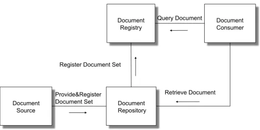
• Cross Enterprise Document Sharing (XDS): in the profile that dic-tates the guidelines to exchange of clinic documentation among companies and sanitary structures of various type (hospitals, med-ical clinics, privates etc). This profile assumes that each organiza-tion belongs to one or more Affinity Domain. Each Affinity Do-main consists of sanitary organizations, which subscribe policies and shared an technological infrastructure in order to exchange among them clinical documents. The policies object of the agree-ments regard aspects of patients identification, access control, ob-taining consent for data treatment. They regard also the format, the content, the structure, the organization and the representation of clinical informations. So, it enables a number of health-care de-livery organizations belonging to an XDS Affinity Domain to share clinical records in the form of documents as they proceed with their patients care delivery activities; Figure 2.1 shows the XDS profile. At the core of XDS there is the document repository and docu-ment registry actors which respectively deal with storing health
documents and storing meta-data about these documents to facili-tate their discovery. The data are produced by a document source actor, typically a medical doctor in a hospital. A community may rely on more than one repository to store the produced documents, however, all the meta-data must be stored and submitted within one registry. A document consumer actor can use the meta-data to know which repository contains the documents of interest. A patient identity source actor feeds patient identities to the registry. Since XDS does not resolve document sharing among multiple affin-ity domains, the Cross-Communaffin-ity Access (XCA) profile specifies how medical data held by other communities can be queried and retrieved.[34]
• Cross Community Access (XCA): this profile defines the concrete guidelines for exchange of documents. In it is defined the concept of Community as set of sanitary structures, which subscribe poli-cies and adopt shared communication protocols in order to shared clinical documentation. Each community is identified by a unique code (Home Community Id). In this profile are added two new actors, Initialing Gateway (it takes in charge of all transaction in exit from the local community and forwarding them towards the other communities) and Responsing Gateway (it manages all en-tering flows from other communities and it forwards it to actors which belong to local community). In other words, it supports the means to query and retrieve relevant patient medical data held by other community. The big advantage deriving by the XCA use is the interoperability that it permits. The operability is both be-tween communities structured internally second the XDS profile, both between communities that don’t adhere to XDS, or developed according legacy principles;
• Patient Identifier Cross-referencing (PIX): supports the cross refer-encing of patients identifiers from multiple Patients Identifier Do-mains;
• Patient Demography Query (PDQ): provides ways for multiple dis-tribuited applications to query a patient information server for a list of patients, based on user-defined search criteria, and retrieve a patients demographics information directly into the application.
• Audit Trail and Node Authentication (ATNA): establishes secrity measures which, together with the Security Policy and Procedures, provide patient information confidentiality, data integraty and user accountability;
• Basic Patient Privacy Consents (BPPC): provides a mechanism to record the patient privacy consent(s), and a method for Content Consumers to use to enforce the privacy consent appropriate to the use. Document Source Document Repository Document
Registry Document Consumer
Provide&Register Document Set
Retrieve Document Query Document
Register Document Set
Figure 2.1: The XDS Profiles
These profiles are building blocks upon which one can develop a number of architectures, but they have also some limitations in the EHR exchange that are explained in the next section.
2.5
Current Limitation of IHE for EHR
ex-change
IHE based systems supports interoperability on interface level so that EHR applications of different vendors can be integrated. The IHE In-tegration Profiles leave details open for implementation, thus different vendors can create their own systems. This means that the interpre-tation may lead to slyghtly different systems. IHE addresses this issue
defining a set of IHE compliant test process. The process culminates in a week long interoperability-testing event known as ”Conectathon”[25]. Apart from the commercial IHE compliant software, there also exists many open source solutions that define one or more of the above speci-fied integration profiles.
Semantic interoperability is an important aspect to guarantee that data are interpreted identically among EHR applications. IHE has recognized the importance of semantic interoperability and aligned their Integration Profiles with internationally accepted standards for semantic interoper-ability such as the Clinical Document Architecture (CDA) [23] and com-mon medical dictionaries such as LOINC [27] and SNOMED [9]. The common data format increases the likelihood that identical meaning of data can be preserved during exchange between EHR systems. With currently available technology such as CDA, a very finegrained structure can be applied to clinical data which allows even a languageindependent identical interpretation [36]. CDA however comes with some limitations such as has no ontological basis and lacks cognitive structure [33] (i.e. all CDA based records are acts).[35]
The XDS profile defines a coupling of facilities/enterprises for the purpose of patient-relevant document sharing.
Within the XDS profile, the health-care enterprises that agree to work together for clinical document sharing is called the Affinity Domain. Within an affinity domain, there can be more than one independent repositories. The assumption is that there exists only one registry where the meta-data regarding documents are stored, such data will indicate to the interested document consumer, in which repository reside the docu-ments of interest.
Another assumption is that XDS is not concerned with the management of dynamic information that is not document-oriented, such as allergy lists, medication lists, problem lists, etc [26]. A means to access this information in a structured form and to manage updates to such dynamic clinical information is still missing.
XDS defines document sharing within an XDS affinity domain. As ad-dressed in [24], XDS does not resolve the sharing of patient-relevant health-care information among multiple IHE environments. This would mean to define how a request for EHR would identify other IHEs which have data about a patient, how to identify the patient in the other IHE
and how to request patient information from the IHE.
The Cross-Community Access (XCA) profile already defines a means to query and retrieve EHR held by other communities by specifying a gate-way that encapsulates all the incoming and outgoing cross-community communications. The XCA profile defines community a grouping of fa-cilities/enterprises that have agreed to work together using a common set of policies for the purpose of sharing clinical information via an es-tablished mechanism. A community is identifiable by a globally unique id called the homeCommunityId. Membership of a facility/enterprise in one community does not preclude it from being a member in another community. Such communities may be XDS Affinity Domains which de-fine document sharing using the XDS profile or any other communities, no matter what their internal sharing structure. Communities can be composed into hierarchical collections of communities which are called meta-communities.
XCA contains a gap in the communication of patient identities as it requires the community who initiates a query towards another commu-nity to determine the correct patient identifier of the patient under the authority of the receiving community [24]. It is also assumed that the communities have a pre-established agreements and knowledge of one another.
2.6
Summary
In this chapter we have introduced the eHealth context, and the advan-tages that it can lead. We started by explaining our motivating scenario. We will carry this throughout the thesis. We focus on the part of eHealth regarding the data exchange, We defined what are the Electronic Health Records (EHRs), and illustrated the existing solutions to EHR exchange that are proposed by IHE. We focused on IHE due to the high world-wide adoption of such standards. We explained the IHE profiles that are involved in the data exchange and pointed out some of the limitations of such profiles. We also describe how these profiles limit the realisation of our motivating scenario.
To Overcome such limitations we eill focus on semantic-agent based solu-tions as they are regarded as a modular solution on the highly distribuited and heterogeneous scenarios.
Chapter 3
Knowledge Representation
Knowledge Representation is a branch of artificial intelligence that stud-ies the way in which the human reasoning is done, defining symbolisms and languages which permit to formalize the knowledge, to make it un-derstandable to the machines, allowing automatic reasoning (through in-ference of already present knowledge) in order to get new knowledge. [29] The research in the field of Knowledge Representation is usually focused on the method to provide a high-level description of the world, that can be actually used to build intelligent applications.[29]
Intelligence: system’s ability to find, based on knowledge acquired and represented explicitly, some implicit consequences.
This chapter is organized as follows: in the Section 3.1 we briefly de-scribe the origins of Knowledge Representation; in the Section 3.2 we give an explaination of the basis of Description Logics, by introducing the Description Logics SHOIN (D) by describing its characteristics. We also present the Ontology Web Language, the standard of W3C1 that
implements the SHOIN (D). Finally in Section 3.3 we conclude and summarise this Chapter.
3.1
History of Knowledge Representation
The first approaches in the field of Knowledge Representation were in the years seventy, and they were divided in two different tipologies [4]:
• based on the logic: their origin was the idea that the predicate calculus could had been used to catch the world’s facts;
• not based on the logic: the idea was based on structures like net-works, and they derive from experiments regarding the capacity of human mind to remember concepts and performs tasks ;
The second approach [29] was the one pursued, but there was a need to equip it with a semantic representation, seeing that each component present in the Knowledge had a different behaviour, despite, it was iden-tical to other. Therefore, to these specifications was given a semantics for representing structures, so that hierarchical structures could be exploited. This could have led to a gain, both in terms of easily of representation, and efficency of reasoning. The basic elements identified were:
• unary predicates: representing sets of individuals;
• binary predicates: representing sets of binary relation between in-dividuals;
Later, it was discovered that this representation did not captured the constraints of interested structures with respect to the logic, but it could only be considered as part of them.
3.2
Description Logics
These were the directly evolutions of structures based on networks , where an additional element called Role was specified in addition to the classical IS-A relation. A Role is a characteristic which permits to represent an other type of relationship. The Role is a link which starts from a node, arrives in another node, and holds a label.
The remaining problem was to define a precise characterization of the present elements and which kinds of relationships could be present (ie define the complete syntax and semantic for all elements involved). Sintax: was introduced a new abstract language resembling to other formalisms already present. So, first, were introduced two new disjoint alphabets of symbols, used for denoting:
Figure 3.1: Example of a network with Role relation
• Atomic Role:represented by predicates of binary symbols, whom express links between nodes:
Semantic: was given a concrete meaning to these two alphabets, to provide an unique interpretation;
• Concept: is a sets of individuals;
• Role: is a set of relations betweens of individuals:
The union of Concepts and Roles present in a context defines its domain, that is the scheme of the Knowledge Base.
Figure3.1 shows a network extended with the Role Relationship. In this figure are shown some IS-A relations, which model the hierarchy of the network, and a Role called hasChild. This meaning that a element of set Patient can be connect to a element of the set Person through the relationship hasChild.
3.2.1
Knowledge Base
The main idea was give a precise specification of the functionality pro-vided to the Knowledge Base, particulary to the inference that it could be capable to perform, and indipendently from the single implementa-tion. So an interface Tell&Ask was created with the purpose of be able to create the Knowledge Base (Tell), and provide a deduction service (Ask).
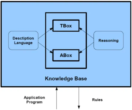
A knowledge representation system based on the Description Logics pro-vides the means for install the Knowledge Base, to make reasoning over their contents and to modify them. As showed in figure3.2 a Knowledge Representation System contains three fundamental elements:
• Terminological Box (TBox) [29]: is the structure of the applica-tion domain, which defines its vocabolary. It represents the syntax of the domain, and it contains concepts and relationships between them. The TBox is the fixed for a specific domain.
• Assertional Box (ABox) [29]: is the population of the applica-tion domain, that represents the extensional knowledge. Here are inserted the individuals, each of them with the concept to which belongs and the relationships in which is involved. The ABox is in continued changing.
• Reasoning [6], [15]: is the service thank to which is possible to deduce new knowledge
The reasoning as central service is an important characteristic. It allows to infer explicitely new knowledge from that implicitely contained in the Knowledge Base. Some inference patterns already present in other applications are used to understand and structure the world, in order to classify concepts and individuals to permit reasoning.
• concept classification: determines the relation between concepts of a given terminology, so that a subsumption’s hierarchy can be build;
• individual classification: determines if a given individual is always an instance of a determinate concept;
Figure 3.2: Knowledge Representation System based on Description Logics
In order to providing formal reasoning on the Knowledge Base were in-troduced the Description Logics, which are explained in follow section. The Description Logics should answer to queries in a reasonable time, and primarily they should ensure that the response provided is certain. Unfortunately the response time is not always ensured; decidability and complexity of the inference problems are dependent by the expressive power of the Description Language. In fact, Description Languages too expressive are useful to resolve inference problem with high complexity, but they can be undecidable, while Description Languages with efficent reasoning procedures may not be sufficiently expressive to represent im-portant concepts of an application [1].
The Description Logics descend from network infrastructures, and there are based on three ideas on which have largely shaped their development:
1. the sintactic base blocks are:
a) atomic concepts (belong to the TBox); b) atomic roles (belong to the TBox);
c) individuals (belong to the ABox);
2. implicit knowledge on the concepts and the individuals can be auto-matically inferred with the help of inference’s procedures, of which the main are:
a) subsumption relations between concepts;
b) instance relations between individuals and concepts;
3. the expressive power of the language is limited to a little set of atomics constructors, starting by them is possible build complex concepts and roles descriptions;
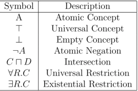
Above we have said that starting from the elementary descriptions of atomic concepts and atomic roles, is possible build complex descriptions, exploiting concept constructors. The set of the constructors used, iden-tifies the complexity of the language. In Table 3.1 we show the set of concept’s constructors for the less expressive language AL. Starting with AL, and adding new constructors is possible obtain languages of any ex-pressivity [5].
Symbol Description A Atomic Concept > Universal Concept ⊥ Empty Concept ¬A Atomic Negation C u D Intersection
∀R.C Universal Restriction ∃R.C Existential Restriction
Table 3.1: AL: Conventional Notation
Abstract notation: A & B for atomic concepts, R for atomic role, C & D for concept descriptions.
The explanation of the Conventional Notation showed in table3.1 is the following:
• the Atomic Concept is a set of individuals;
• the Empty Concept is an empty set;
• the Atomic Negation is the set of individuals of the universe that are not present in the Atomic Concept A;
• the Intersection between C and D is the set of individuals present either in C that in D;
• figure 3.3 shows the Universal Restriction, and, it is a set of indi-viduals that participate or not in the relationship called rel1. But if an individual participates in this relationship, this one can be directed solely towards individuals of Class1.
• figure 3.3 shows the Existential Restriction, and, it is a set of in-dividuals that participate in the relationship called rel1. Unlike the Universal Restriction if an individual participates in this rela-tionship, this one can be directed towards individuals of different Classes.
Figure 3.3: Class Restrictions
As introduced previously the TBox is fixed, and it defines the domain to be modeled. It can be compared with the schema of a Database. The ABox, which changes continuously, is the actual instance contained inside the Database. There is a substantial semantic difference between
ABox and a instance of Database, because an instance of a Database represent exactly one interpretation, precisely that are the classes and relations present in the schema that are interpreted from the object in the instance, while an ABox represents some different interpretations, exactly all various domains modeled. This means that absence of information, contrary what happens in the Database where is interpreted as negative information, in the ABox, it is interpreted only as lack of knowledge. In other words the semantics of the ABox is an open-world semantics [28].
3.2.2
SHOIN (D)
This is the Description Logic used in the semantic extension of TuCSoN [30]. It extends the expressive capabilities of the AL with this charac-terization:
• S: indicates the possibility of write expressions of logic equivalence and of subsumption using base terms (true & false), terms com-pounded from operators (and, or & not), quantificators role simple (∀R.C & ∃R.C ) and the roles transitivity axiom;
• H: indicates the possibility to make subsumption between roles, in order to establish their hierarchies.
– subsumption (R v S): the role S subsume the role R;
– equivalence (R ≡ S): the role R is equivalent to the role S. This is not directly expressible, but obtainable by the double subsumption R v S and S v R;
• O: indicates the possibility to define terms for enumeration; • I: indicates the possibility to define inverse role, which permits to
invert domain and range of a role;
• N : indicates the possibility to define cardinality not quantified; • D: indicates the possibility to use concrete domains, denoted by
atomic terms, like naturals, floats, characters, strings; For more detail about the Description Logics refer to [6]
3.2.3
Ontology Web Language (OWL)
Since 2044 OWL is a W3C recommended standard, it is a practical real-ization of a Description Logic known as SHOIN (D) [22]. Using OWL it is possible to define classes (also called concepts in the DL literature), properties, and individuals. An OWL ontology consists of a set of class axioms that specify logical relationships between classes, which consti-tutes a TBox (Terminological Box); a set of property axioms to specify logical relationships between properties, which constitutes a RBox (Role Box); and a collection of assertions that describe individuals, which con-stitutes an ABox (Assertional Box). Classes are formal descriptions of sets of objects. Class axioms allow one to specify that subclass (v) or equivalence (≡) relationships hold between certain classes and the do-main and range of a property. Assertions allow one to specify that an individual belongs to a class (C(a) means that the object denoted by a belong to the class C), and that an individual is (or is not) related to another individual through an object property (R(b,c) means the object denoted by b is related to the object denoted by c through the property R). As said in section 3.2.1 complex classes can be specified by using Boolean operations on classes: C t D is the union of classes, C u D is the intersection of classes, and ¬ C is the complement of class C. Classes can be specified through property restrictions: ∃ R.C denotes the set of all objects that are related through property R to some objects belong-ing to class C at least one; if we want to specify to how many objects an object is related we should write: ≤nR, ≥nR, =nR where n is any natural number; ∀ R.C denotes the set of all objects that are related through R only to objects belonging to class C. To realise the framework, we need to express some preconditions for the reaction part of the reaction rules. Every precondition can be a class assignment as defined by OWL DL, a query executed thanks to the reasoning services of a reasoning tool or, a Prolog predicate used to construct some specific function2. In order to
execute a reaction, all its preconditions must be satisfied3.
Given that there is not an official standard query formalism for OWL DL, in this paper we decide to adopt this one that is inspired from [8]
2In what follows we do not give the specification details of such predicates as they
are intuitive, and, with a straightforward specification.
3 As in Prolog, it is possible to specify preconditions to be executed in or by
surrounding those with round brackets followed by a semicolon. Section5.4 makes use of such specification.
and allows to express the queries that are available in the DL Query tab of Prot`eg`e4.
?-C v D ⇒ true/false checks the subclass relationship; ?-C ≡ D ⇒ true/false checks class equivalence;
?-C ⇒ true/false checks if the class is satisfiable; ?-C(a) ⇒ true/false instance checking;
?-C(*) ⇒ {a1,....an} retrieval, C can be a complex class.
In our implementation those queries are executed using the Java Jena API 5.
3.3
Summary
In this chapter we introduce the concepts behind the description logics. We explain the SHOIN (D) which is an extension of AL. In this thesis each tuple centres contains a ontology which model the eHealth context. We show how we model these issues in Chapter5. In the next chapter we explain how Semantic TuCSoN uses SHOIN (D) to reason about tuples generated in the system framework.
4http://protege.stanford.edu/ 5http://incubator.apache.org/jena/
Chapter 4
From tuple spaces to tuple
centers
In this chapter we introduce TuCSoN, a framework to share information that we use in order to modelling the exchange of EHR among commu-nities. TuCSON is a framework that permits to exchange information on form of Tuple, in a distribuited environment.
This chapter is organized in this mode: in the section4.1 we explain the context of information’s dimension introducing the coodination amond entities; in the section 4.2 we explain the tuple space argument, speak-ing briefly of the most important, the Linda tuple space, introducspeak-ing its limitations; in section 4.3 we speak of the tuple centres and how they can overcome the limitation of tuple spaces, and we focus our interest on TuCSoN, explaining its characteristics and introducing its semantic ex-tension. Finally in Section4.4we conclude and summarise this Chapter.
4.1
Coordination among entities
In any meta-model of software engineering there are two different dimen-sions:
• computation: general elaboration of data, that consists, given an algorithm and some input data, obtain some data in output; • coordination: how the space of the interactions is constrained;
In this thesis we are interested to the argument of data exchange, so, we focus our attention only on the coordination. In the coordination’s dimension the first class entities are [7]:
• coordination model: is the glue that binds separate activities into an ensemble;
• coordination language: is the linguistic embodiment of a coordina-tion model;
• coordination middleware: is the execution environment for deploy-ment, execution and manage of the coordination abstractions. and the meta-model of coordination proposed is:
• coordination entities: the entities which interactions are governed by the model;
• coordination media: the abstractions that allow and regulate the interaction among coordinables;
• coordination laws: the laws that define how the coordination media behaves in response to interaction events;
There are two main types of coordination models. In the first, called data-driven, the coordinables cooperate and/or compete among them producing and using information that are presents in some shared space. And the second, called control-driven, where the coordinables work gener-ating and reacting to events or signals exchanged in well defined channels. Both approaches have some positive and some negative features. In this thesis, we are interested in the data-driven approach. The context of our work has the following characteristics, ideals to work with a data-driven approach:
• it involves open system environments, where the set of coordinables is not known;
• coordinables are in a environment with a high level of autonomy, and they encapsulate their behaviour;
• the environment is a concurrent and distributed system;
The most famous type of data-driven model is the Tuple Space model. In the next section we describe this type of model, and we introduce its main features.
4.2
Tuple Space
Linda is the language for the most important data-driven model called Tuple Space model [20]. It is a coordination language which extends the traditional languages, allowing the construction of application on distribuited environment. It has the feature to be indipendent from ar-chitecture underlying and by the programming language used. Linda im-plements an associative memory (Tuple Space) logically divided among all processes present in the application. Linda is characterized from the following entities individuated below:
• tuple space as coordination media; • tuple as communication language;
• primitive (in, read, out, eval) as coordination language;
In this model the coordination is always left to the coordinables, and this is a big limit, because they have to know the coordination policies of the system, and implement them. This solution is not elegant and it is in conflict with the ortogonality between computation and coordination, in fact, in this model the coordinables have these two behaviours mixed between their.
4.3
Tuple Centre
In order to overcome such a limitation, a number of tuple-based coor-dination models and languages were proposed. The intent was extend the original tuple-space model, by allowing to its behaviour to be pro-grammable so as to embed coordination policies within the coordination media. The concept of tuple centre was developed starting from [10],
where the notion of programmable coordination medium was explicited for the first time. Tuple centres are tuple spaces whose behaviour can be determined through a specification language. This language defines how a tuple centre should react to incoming/outgoing communication events [31]. Unlike tuple spaces, the behaviour of tuple centres can be programmed with reactions, in order to encapsulate coordination policies within the coordination medium.
4.3.1
TuCSoN
TuCSoN (TupleCentres Spread over the Network) [32] is an infrastruc-ture based on the Tuple Centre concept. It permits communication and coordination among agents, which work by inserting, reading and con-suming tuples in this Tuple Centre. The operations needed to work on the tuple centre can be either blocking or non-blocking. TuCSoN has all the features present in a classic Tuple Centre, and it provides a ulte-rior one, which has already been discussed as extension of Tuple Space. This feature is the possibility of create multiple Tuple Centres in the same node, allowing the subdivision of the work among more Tuple Cen-tres. TuCSoN implements the idea of programmability of Tuple Centres through ReSpecT [2]. ReSpecT is a logic-based language that allow to specification the tuple centre behavior through a set of first-order logic tuples.
4.3.2
ReSpecT
Since ReSpecT is Turing-equivalent any computable coordination policy required by specific application scenario can be in principle embedded inside a ReSpecT Tuple Centre. A specific ReSpecT can associate to any primitive performed on the Tuple Centre, a specific reaction implemented to manage the coordination of the system.
An reaction can be inserted into the tuple centre with a special primitive called set spec, which must contain the ReSpecT code (or must specify the file where the ReSpecT code is). A reaction ReSpecT has this form reaction (Event, Guard, Body), which has the following meaning:
• Event: is the event (primitive in the Tuple Centre) that triggers the reaction;
• Guard: is a couple of parameters whom defining the proprieties of the triggering event;
• Body: is a list of instructions that the reaction must perform; In the body can be writing a set of elementary non-blocking operations, but not only, in fact TuCSoN is build over tuProlog, and it is integrated with JAVA [12], so is possible use Java and Prolog code inside the re-action. ReSpecT being a coordination language, must check that all is well done for the correct execution, otherwise it must go back. To satisfy this requirement it has a rool-back mechanism, which deletes all actions already done if something go wrong before the end of the reaction.
4.3.3
Semantic TuCSoN
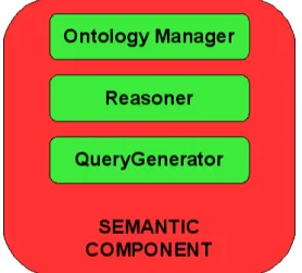
Semantic TuCSoN is an extension of TuCSoN which aims to overcome the syntactic limits of the classical Tuple Centre, and provide a semantic support. The idea has been developed in [30], and the work done had two main targets, strictly dependent to one to another. The first target was the necessity to insert in this framework the possibilty of working with semantics, in order to overcome the syntactic limitations. For this, the ontologies and well known tecnologies for work over them, have been used. In fig4.1 are showed all components created to permit semantic in TuCSoN.
The correlation between the components and the technologies is the fol-lowing, as showed in figure4.2 :
• Ontology Manager: uses the OWL Ontology to obtain and manage an ontology;
• Reasoner: uses Pellet Java Library 1 to permit reasoning on the
ontologies;
• Query Generator: uses Jena Library 2 to create Query SPARQL3,
in order to query the ontology;
1 clarkparsia.com/pellet/ 2 incubator.apache.org/jena/ 3 www.w3.org/TR/rdf-sparql-query
Figure 4.1: Semantic Component
• Semantic Component: is the component, that using the other com-ponents, permits to coordinate all work regarding the new semantic part of TuCSoN;
Figure 4.2: Block Scheme
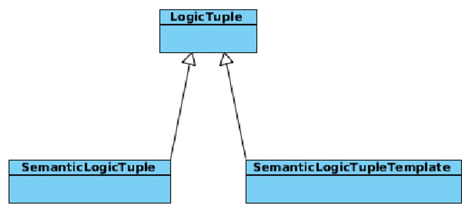
In the second extension, a mechanism was provided to insert and retrieve information exploiting not only the Tuples seen as up at this time, but also in a semantic way. To realize this, the Java class LogicTuple, has been extended in two directions, as showed in fig 4.3. One to permit the inserting semantic information through a new definition of Semantic
Logic Tuple, and the second one to permit to get semantic information through a new definition of Semantic Logic Tuple Template.
Figure 4.3: Extension of LogicTuple Class
These extensions use the theory of Description Logic SHOIN (D). In fact the SemanticLogicTuple is modelled in a way that it permits to ex-press sentences whose describing the name of individuals, their data and their relationship on this Description Logic. While the SemanticLogic-TupleTemplate permits to express sentences whose describing all concept descriptions allowed by SHOIN (D), in order to retrieve the information required.
At the present this extension permits to insert and retrieve knowledge throught Semantic Tuple and Semantic Template, but it does not permit to use a Tuple Centre as very Semantic Tuple Centre, which should contain a Knowledge Base, and can not works in persistent manner as the objective of this thesis requires. In fact a Semantic Tuple Centre should be a container of persistent knowledge, where should be possible insert information (Tell), retrieve information (Ask) and reasoning about it.
4.4
Summary
In this chapter we have introduced the theory behind the TuCSoN frame-work, starting from the concept of coordination, arriving to the concept
of Tuple Centre, via Tuple Space. We have also described the extension of the semantic component which enables TuCSoN with the capability to work on Knowledge Base. Finally we have explained that this extension is still not complete in order apply it to our motivation scenario a real working framework. In the implementation chapter we will show all the mechanisms that it needs in order to work in a complete mode. We also show how we apply it to Semantic Health Coordination Framework.
Part II
Framework
Chapter 5
The Semantic Health
Coordination Framework
Motivated by the need to have a system for EHR exchange in an dis-tribuited environment, in this chapter we describe how model the con-cept of distributed communities. We connect them in a tree structure, and define coordination primitives to support the EHR exchange. We specify such framework using Semantic TuCSoN and a set of agent that coordinate over the platform.
We define a semantic knowledge base and assume that every community has the same schema. The difference among them is not their semantic structure, but is the data that this structure contains. In fact every community can be different from the others in terms of its organisation, the services it offers, the policies it uses, and others characteristics as we show later in this chapter.
What it follows has been previously discussed in [34].
The chapter is organized as it follows: in section5.1we model the system, explaining how each community is structured, what type of tuple centres are present inside the community, and how is built the topology of the system; in section5.2we explain the ontology community present in each tuple centre of to the system, we then describe all present entities in it (Classes and Properties); in section5.3we introduce the concept of Policy Tuple Centre, explaining all tasks that it performs, and all primitives of coordination defined inside this type of tuple centre; in section 5.4 we introduce the concept of Community Tuple Centre, which is the tuple
centre that takes in charge the task to perform the more expensive queries in the knowledge base (research of patients and communities). Finally in Section 5.5 we conclude and summarise this Chapter.
5.1
The Architecture of the System
Every community containt a set of data which are semantically described with an ontology. The ontology describes the concepts of the community, using the TBox. The actual data, represented in the ABox, will be different in the various communities. The union of ABox and TBox builds the Knowledge Base of a single community, on which the system can reasoner to obtain the information wished.
An Affinity Domain as defined and described in Chapter 2 can be seen as a Community. The Community will encapsulate the EHR system and the mechanisms for modeling, modifying and exchanging EHR data. Figure5.1 shows the logical architecture of a Community.
Figure 5.1: Logic Architecture of a Community.
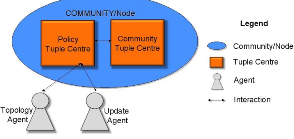
In this figure is shown that each community has inside it two tuple centre, the Policy Tuple Centre and the Community Tuple Centre. The Policy Tuple Centre (PTC) deals with incoming requests from other communi-ties to either connect into a tree structure or to subscribe to notification of events. For every Community there can be a Father Commu- nity and
many Child Communities (See Fig ). PTC specifies the coordination primitives for adding, and removing a child or a father to a Community and the primitives for allowing subscription and unsubscriptions from other Communities. These tuple centres are semantics tuple centres of Semantic TuCSoN framework. At the moment we use a soft model of agency where agents simply react to specific messages exchanged in the tuple centres as opposed to a hard model of agency where the agents have complex cognitive models to perform complex reasoning. TuCSoN thanks to the ReSpecT language [2] can enable the coordinations of the different communities. In fact, in each Policy Tuple Centre and the Com-munity Tuple Centre are specified the ReSpecT reactions that coordinate the interested communities. The Community Tuple Centre (CTC) is an additional coordination module used to evaluate search queries that are generated in the system. Communities generate queries to search a new community or to search data related to a patient. Such search queries are computationally expensive thereby we evaluate them outside the PTC. In fact the PTC receives also requests for search queries, but it forwards them to the CTC which may either find the result of a query or prop-agate it to the PTC-s of the father and the child communities. In this way we evaluate expensive queries in parallel to the normal functionali-ties offeered in PTC, and do not directly expose the CTC to the whole system.
For each community we have identified two main agents needed for this infrastructure :
• Topology Agent: is the agent responsible of sending and catching messages regarding the context of manage the topology of the entire community system;
• Update Agent: is the responsible of sending and catching messages regarding the manage of the knowledge base;
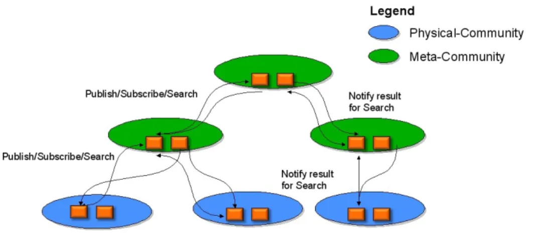
After a careful analysis we have decided to structure our topology in a tree structure as showed in figure 5.2. There are two reasons for our choise. The first is that the structure will be a dinamic one, where the communities can be added or removed in a self-organising manner. In this way, only the direct interested have to be involved. The second is, because there could be present some queries, where the addressee community is not known. The search of the community could be computationally
Figure 5.2: High view of the tree structure.
expensive for each node. With a tree structure, the queries propagation is enabled only in the branches connected with the requester, and possibly forwarded in their connections. The research will continue up to which the information will not be found. In this way, can be avoided the send of search message in a broadcast manner. In this tree structure, you can see two type of community, the meta-community and the community. The difference between them is that in the meta-community there is only the infrastructure shown in figure 5.1, while in the community there is also the physical healthcare system inside them. Furthermore, real world communities are usually organised following a tree structure due to their geographical disposition within a region and a state. Therefore, keeping a tree structure, we simplify the representation of real communities within our system.
Figure 5.2 shows also the presence of some interaction. We model the system in a way such as all communications must pass through the PTC. In this way, it can check the policies and decides if the communication is allowed or not. Instead, the CTC can only send information to PCT.
5.2
Ontology Community
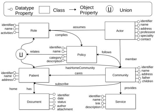
As we explained above, every community has its own knowledge base. The schema, represented by the TBox and RBox, is fixed and invariable for all the Communities. The TBox represents all the classes present in the knowledge base, and their IS-Relationships, while the RBox repre-sents all object properties and datatype properties present in the knowl-edge base. Each property has its domain and range. Figure 5.3 shows the complete schema of the OWL Community Ontology1 present in each
node. Community Community Document Document Patient Patient identifier name address identifier date identifier name
address fatherchildren
status author hasHomeCommunity Role Role identifier name activities Policy Policy identifier name category description Service Service Actor Actor profession name contact address identifier speciality assumes member complies follows provides has cares subscribe identifier name link description ∐ relates attachment Datatype Property Class Object Property ∐ home Union
Figure 5.3: The OWL Community Ontology.
Based on [8], we formilise the schema presented in Figure 5.3 The RBox of the Community Ontology contains the following object properties, where their name is followed by the domain and the range for everyone.
1The full ontology can be found in
has : Patient → Document; cares : Community → Patient; subscribe : Community → Patient; member : Actor → Community; provides : Community → Service; follows : Community → Policy; assumes : Actor → Role; complies : Role → Policy;
relates : Policy → (Patient t Role);
hasHomeCommunity : Patient → Community;
We also specify if any property has got the attribute of functionality (or inverse functionality), as follows:
InvFun(has); InvFun(cares); InvFun(provides); InvFun(follow); Fun(relates); Fun(hasHomeCommunity);
The TBox contains the subsequent axioms that defines cardinality re-strictions for the defined properties:
Document v =1 has−; Service v =1 provides−; Patient v =1 cares−; Actor v =1 member; Policy v =1 follows; Policy v =1 complies;
We provide an example in order to clarify the meaning of the formalism above used: the property relates has how domain an individual of Policy class and how range an individual of union of Patient class with Role class, and has the attribute of functionality
This means that an individual belonging to Policy class can partecipate to an only one property relates. And the property has how range or an individual of a Patient class or a individual of Role class.
In the following section we give a description of any definition introduced above, explaining their meaning in our domain.
5.2.1
Entity Description
Community: represents a community, which can be a meta-community or a meta-community
• each Community can provide a set of Services and a service have to be provided always and only to a community;
• each Community can follow a set of Policies and a policy have to be followed always and only to a community;
• each Community can cares about Patients and a patient have to be cared always and only from the home community of this commu-nity;
• each Community can subscribe to a Patient of another Community in order to receive notification in case of somewhere regarded this patient happened.
Service: represents a set of services provided from a community Are the service that each community makes available to patients and involving the possible content of EHRs.
Policy: represents a set of policies that a community has to follow
The Policies are aimed to aid the integration of the Communities by mak-ing explicit under which rules the data are shared. In particular, they state which policies are applied to other communities which require pa-tient data or subscribe to papa-tient data in a community, or merge or delete
themselves from the community structure. Such policies are enforced in the Policy Tuple Centre.
• each Policy can be related to a Role or to a Patient, but not at same time;
• each Patient has one and only one Community as home community; Patient: represents a patient of a community
• each Patient has got a set of Documents, and a document has to belong always and only to a patient;
• each Patient has one and only one Community as home community; Document: represents part of a patient health record
Are generated and stored within a community. Every document relates to a specific patient. When a document is generated, it has an author, which is an actor in the community and has a set of properties which in-dicates the content of the document. The community that generates such documents can also update their status by making documents obsolete or deleting them.
Actor: represents an actor of the community
Such actors must perform their activities in complying way with the Policies of the Community.
• each Actor must be member of Community, exactly the home com-munity of this comcom-munity;