DOTTORATO DI RICERCA IN
INGEGNERIA CIVILE E
INDUSTRIALE
University of Calabria
DIMEG – Department of Mechanical, Energy and Management Engineering
Ph.D. Thesis
XXX Cycle (2014-2017)
Ph.D. in Civil and Industrial Engineering
Surface Integrity enhancement of aerospace
components produced by subtractive and
additive manufacturing processes
Candidate
Stano Imbrogno
Ph.D. Coordinator:
Prof. Franco Furgiuele
Supervisor:
1
Index
Lists of Figures ... 3
Lists of Tables ... 9
Abstract ... 10
Abstract (lingua italiana) ... 11
Acknowledgments ... 13 CHAPTER I ... 14 Introduction... 14 1.1. Research objectives ... 17 1.2. Dissertation outline ... 18 CHAPTER II ... 20
Advanced and conventional manufacturing processes of aerospace metal components ... 20
2.1 Aerospace materials for engine, structural and engine components ... 20
2.1.1 Titanium alloy – Ti6Al4V ... 24
2.1.2 Aluminum alloy – AA7075-T6 ... 27
2.2 Additive and subtractive manufacturing processes of aerospace metal components... 29
CHAPTER III ... 39
Machinability and surface integrity investigation of additive manufactured and wrought parts of Ti6Al4V alloy in semi-finishing conditions ... 39
3.1 Experimental work – semi-finishing operations on Ti6Al4V EBM, DMLS and wrought... 40
3.1.1 Design of Experiments and experimental set-up ... 41
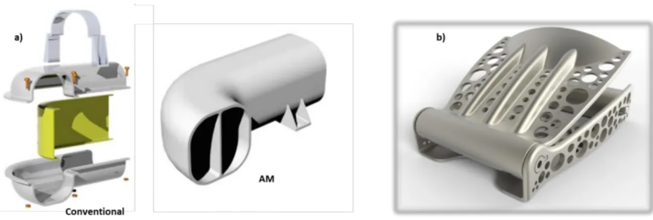
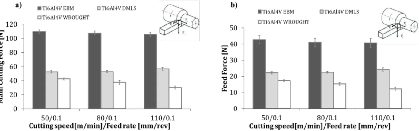
3.1.2 Cutting forces ... 41
3.1.3 Temperature analysis ... 45
3.2 Surface Integrity analysis of Ti6Al4V EBM, DMLS and wrought ... 47
3.2.1 Topography - Surface Roughness ... 47
3.2.2 Affected Layers and microstructure deformation ... 50
3.2.3 X-Ray Diffraction analysis (XRD) ... 59
3.2.4 Surface and Subsurface hardness ... 62
CHAPTER IV ... 68
High speed machining of the aluminum alloy AA7075-T6 and the application of a severe plastic deformation (SPD) process... 68
4.1. Experimental work – high speed machining of AA7075-T6 under dry and cryogenic conditions 68 4.1.1 Design of Experiments and material selections ... 69
4.1.2 Cutting Forces ... 70
4.1.3 Temperature analysis ... 72
2
4.2.1 Topography – Surface Roughness ... 73
4.2.2 Affected Layers and microstructure analysis ... 74
4.2.3 X-Ray Diffraction analysis (XRD) ... 79
4.2.4 Surface and Subsurface hardness ... 81
4.3 Equal Channel Angular Pressing and machining process on aluminum alloy ... 86
4.3.1 Design of the ECAP die ... 87
4.3.2 ECAP tests on AA7075 ... 88
4.3.3 Orthogonal cutting tests of AA7075 ... 89
4.4 Comparison of the experimental results ... 90
4.4.1 Microstructure and hardness measurements ... 90
4.4.2 X-Ray Diffraction analysis ... 93
CHAPTER V ... 96
Finite element modeling and analysis to investigate the surface integrity characteristics during machining processes ... 96
5.1 Numerical Simulation of manufacturing processes – State of the art ... 97
5.1.1 Material constitutive modeling in machining simulation ... 97
5.2 3D FE model of semi-finishing of Ti6Al4V produced via EBM and DMLS technology ... 108
5.2.1 Material constitutive model ... 108
5.2.2 3D FE model of Ti6Al4V semi-finishing machining process ... 118
5.2.3 FE Calibration ... 121
5.2.4 FE Validation ... 122
5.2.5 Surface Integrity Analysis ... 125
5.3 3D FE model of high speed machining of AA7075-T6... 129
5.3.1 Material constitutive model ... 129
5.3.2 FE Calibration ... 135
5.3.3 FE Validation ... 136
5.3.4 Surface Integrity Analysis ... 138
Concluding Remarks ... 142
Future research directions ... 143
3
Lists of Figures
Figure 1: Different mechanical and structural aircraft components and the materials employed. ... 14 Figure 2: Representative scheme of the research activities developed in this Ph.D. thesis. ... 16 Figure 3: Flow chart of the Ph.D. thesis. ... 19 Figure 4: Materials and their weight percentages used in the airframes of civilian and military aircrafts (adapted from Mouritz 2012). ... 21 Figure 5: Different mechanical and structural groups of aircraft components and the materials employed. ... 21 Figure 6: a) Yield strength of aluminum alloys and the year of introduction into civils transport services; b) Titanium content % used in military and civils transport aircrafts (adapted from Mouritz 2012). ... 22 Figure 7: a) Boeing 787 fuselage under construction; b) wing and its internal structures made by wing ribs; c) Aluminum alloys used on Boeing 777 (adapted from Starke and Staley 1996). ... 23 Figure 8: a) blades material at different temperature operative conditions into a representative aerospace jet engine; b) economy of weight achieved in the case of using titanium for engines: 1, large-size; 2, medium-size; 3, small-size (Rolls-Royce Trent 700). ... 23 Figure 9: a) Rutile, b) Ilmenite. ... 24 Figure 10: Appearance of crystal structures of titanium at atomic level (Donachie 2000). ... 25 Figure 11: Effect of cooling rate on the microstructure of an alpha-beta alloy (Ti6Al4V ); (a) α' + β; prior beta grain boundaries; (b) Primary α and α' + β; (c) Primary α and α' + β; (d) Primary α and metastable β; (e) Acicular α + β; prior beta grain boundaries; (f) Primary α and acicular α + β; (g) Primary α and acicular α + β; (h) Primary α and β; (i) Plate-like α + β; prior grain boundaries; (j) Equiaxed α and intergranular β; (k) Equiaxed α and intergranular β; (l) Equiaxed α and intergranular β (adapted from Donachie 2000). ... 26 Figure 12: Bauxite. ... 27 Figure 13: a) Microstructure of AA7075-T6 (MacKenzie 2006); b) FCC crystal structure. ... 28 Figure 14: Al Matrix, η’ dispersed into the matrix and η grain boundaries precipitates (MgZn2) 7xxx series
aluminum alloy aged at 180°C (adapted from Flower 1995). ... 28 Figure 15: Thin Wall Ribs of Boeing aircraft structural part: High Speed vs. Conventional Machining (adapted from Campbell 2006). ... 30 Figure 16: a) and b) SEM micrographs of machined surface; c) and d) SEM micrographs of fracture surface morphology of machined parts (adapted from Wang and Liu 2016). ... 30 Figure 17: a) TEM and b) HAADF-STEM images showing the microstructure of the surface deformation layer in the machined 7055 aluminum alloy (Chen et al. 2017)... 31 Figure 18 : Microstructure on the cross section of the machined samples (dry) and b (cryogenic); c) measured microhardness (Adapted by Rotella 2013) ... 32 Figure 19: a) aircraft duct example; b) Seat buckle produced using DMLS technology (Adapted from Gibson et al. 2010, Dutta and Froes 2016). ... 33 Figure 20: Life cycle of a product from production to the use-phase and recycling (Schmidt et al. 2017). 34 Figure 21: Effect of different manufacturing technologies on “buy-to-fly” ratio. ... 34 Figure 22: Ti6Al4V image compositions corresponding to test block sections. Numbers in horizontal and vertical reference planes at left are Vickers micro-indentation hardness in GPa. Numbers 2 and 4 at right refer to test block (focus offset) numbers. B indicates the build direction (Murr et al. 2012). ... 35 Figure 23: a) roughness surface obtained on AM titanium alloy; b) detailed zone of the surface
(Greitemeier et al. 2016). ... 36 Figure 24: Fatigue limit (at 5 × 10⁶ cycles) compared to surfaces roughness. Rv = maximum profile valley
depth, AB = as-built (adapted by Kahlin et al. 2017). ... 37 Figure 25: Tool wear analysis by SEM images of the tool used to machine a) and b) wrought titanium alloy, c) and d) AM titanium alloy (Bordin et al. 2014). ... 37
4
Figure 26: a) Experimental set-up used to perform machining test under dry conditions; b) Cryogenic delivery system detail. ... 40 Figure 27: Elaboration of the main cutting force (Fz) signal acquired by the piezoelectric dynamometer
during dry turning operation on the titanium bars (Vc 80m/min, f=0.2mm/rev, ap=0.2mm, Ti6Al4V
DMLS). ... 42 Figure 28: Main cutting forces a) and Feed forces b) at varying cutting speed and feed rate equal to
0.1mm/rev (dry conditions). ... 42 Figure 29: Main cutting forces a) and Feed forces b) at varying cutting speed and feed rate equal to
0.2mm/rev (dry conditions). ... 43 Figure 30: Main and feed cutting forces obtained during machining of Ti6Al4V DMLS at feed rate 0.1mm/rev (dry conditions). ... 43 Figure 31: Main cutting forces a) and Feed forces b) at varying cutting speed, feed rate and cooling
conditions. ... 44 Figure 32: a) Cryogenic machining; b) dry machining. ... 44 Figure 33: Thermal gradient signal acquired by the infrared camera during turning operation on the titanium bars and elaborated (Vc =110m/min, f=0.1mm/rev, ap=0.2mm, Ti6Al4V DMLS). ... 45
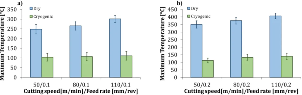
Figure 34: Average value of the maximum temperature at varying cutting speed, feed rate and material machined under dry conditions; a) 0.1mm/rev; b) 0.2mm/rev. ... 46 Figure 35: Comparison of average maximum temperature acquired under dry and cryogenic machining of
Ti6Al4V EBM; a) 0.1mm/rev; b) 0.2mm/rev. ... 46
Figure 36: Average maximum temperature acquired under cryogenic machining of Ti6Al4V EBM at varying cutting speed and feed rate. ... 46 Figure 37: Topographic parameter Ra (Mean Roughness). ... 48
Figure 38: ConScan Surface Profilometer (Anton-Paar) employed to evaluate the surface roughness. ... 48 Figure 39: Roughness Ra measured at varying cutting speed and feed rate for different tested materials. .. 49
Figure 40: Roughness Ra measured on Ti6Al4V EBM machined under dry and cryogenic conditions at
varying cutting speed and feed rate. ... 50 Figure 41: Experimental procedure to prepare the samples for metallographic analysis and optical
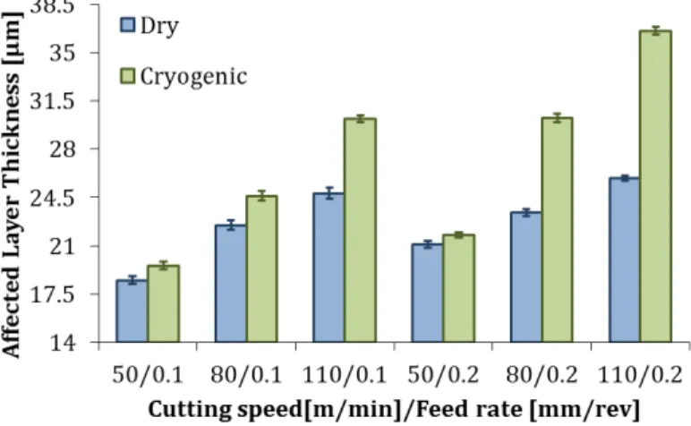
microscopy... 51 Figure 42: a) Sever Plastic Deformed layer on machined Ti6Al4V DMLS; b) bended lamellae due to the deformation imposed by the tool action; c) Measure representative of the plastic deformation within the deformed layer (𝜀 = 𝑡𝑎𝑛𝑔𝜃 = 𝑎/𝑏). ... 51 Figure 43: Affected Layer thickness (AL) at varying cutting speeds, feed rate and materials in dry
conditions. ... 52 Figure 44: Affected Layer thickness (AL) at varying cutting speeds, feed rate and cooling condition measured on the Ti6Al4V EBM. ... 52 Figure 45: Plastic deformation at varying cutting speed and feed rate on different machined material under dry conditions... 53 Figure 46: Plastically deformed layer thickness of machined materials at cutting speed 110m/min, feed rate 0.2mm/rev and ap=0.2mm: a) Ti6Al4V EBM; b) Ti6Al4V DMLS. ... 53
Figure 47: Plastic deformation at varying cutting speed, feed rate and cooling conditions on machined
Ti6Al4V EBM. ... 54
Figure 48: Yield stress depending on α-lamellae thickness (Adapted from Al-Bermani et al. 2010). ... 55 Figure 49: Variation of the α-lamellae thickness due to the tool action on machined surface (cross section). ... 55 Figure 50: Initial microstructure of the Ti6Al4V; a) EBM; b) DMLS; c) Wrought. ... 56 Figure 51: SEM analysis of the machined surface of a) Ti6Al4V EBM; b) Ti6Al4V DMLS
(Vc=110m/min, f=0.2mm/rev, dry conditions)... 56
Figure 52: Optical micrographs and AFM microstructure analysis (Vc = 110 m/min, f = 0.2 mm/rev); (a)
5
Figure 53: Degree of Grain Refinement at varying cutting speed and feed rate for different machined
materials in dry conditions. ... 58
Figure 54: Degree of Grain Refinement at varying cutting speed, feed rate and cooling conditions for machined Ti6Al4V EBM. ... 58
Figure 55: Experimental set-up and sample used to perform the XRD analysis. ... 59
Figure 56: XRD pattern of as produced Ti6Al4V samples. ... 59
Figure 57: XRD pattern of the Ti6Al4V EBM machined under dry condition (f=0.2 mm/rev). ... 60
Figure 58: XRD pattern of the Ti6Al4V DMLS machined under dry condition (f=0.2 mm/rev). ... 60
Figure 59: XRD pattern of the Ti6Al4V wrought machined under dry condition (f=0.2 mm/rev)... 60
Figure 60: XRD pattern of the Ti6Al4V EBM machined under cryogenic condition (f=0.2 mm/rev). ... 61
Figure 61: Nano-hardness measurement set-up and procedure. ... 62
Figure 62: a) Micrograph in dark field of the matrix spot for the nano-indentation test; b) vertical line of tips; c) nano-indentation test results. ... 63
Figure 63: Nano-hardness measurements on the cross section of the samples. ... 63
Figure 64: Nano-hardness at varying cutting speed, feed rate and materials. ... 64
Figure 65: Nano-hardness measured on Ti6Al4V EBM machined under dry and cryogenic conditions at varying cutting speed and feed rate. ... 65
Figure 66: Hardness profile through the dry machined surface; a) Vc=50m/min and f=0.2mm/rev; b) Vc=110m/min and f=0.2mm/rev. ... 65
Figure 67: Hardness profile through the cryogenic machined surface of the Ti6Al4V EBM; a) Vc=50m/min and f=0.2mm/rev; b) Vc=110m/min and f=0.2mm/rev. ... 66
Figure 68: Experimental set-up to perform High Speed Machining. ... 69
Figure 69: Cutting force components in turning operation, Ff feed force, Fc tangential force or main cutting component (adapted by Laperrire 2014). On the right, the two components acquired during the tests. ... 70
Figure 70: Main cutting (a) and feed (b) forces at varying cutting speeds, feed rate and cooling conditions. ... 71
Figure 71: Chip obtained at cutting speed of 1250m/min and feed rate 0.1mm/rev; a) dry conditions, b) cryogenic conditions. ... 71
Figure 72: Rake face and worn edge at cutting speed 1000m/min and feed rate 0.1mm/rev; a) dry conditions, b) cryogenic condition. ... 72
Figure 73: Cutting temperatures at varying cutting speeds and cooling conditions a) f=0.1mm/rev; b) f=0.3mm/rev. ... 73
Figure 74: Ra measurements at varying cutting speed, feed rate and cooling strategy. ... 73
Figure 75: Flank wear at cutting speed 1500m/min and feed rate 0.3mm/rev; a) cryogenic conditions, b) dry conditions... 74
Figure 76: Grain size variation from the machined surface through the depth of the specimens manufactured under dry conditions at varying cutting parameters. ... 75
Figure 77: Grain size variation from the machined surface through the depth of the specimens manufactured under cryogenic conditions at varying cutting parameters. ... 76
Figure 78: Thickness of the material layers where the microstructure changes due to the machining process. ... 76
Figure 79: Optical micrographs of the cross section at cutting speed 1000m/min and varying feed rate and cooling strategy. ... 77
Figure 80: Optical micrographs of the cross section at cutting speed 1500m/min and varying feed rate and cooling strategy. ... 78
Figure 81: X Ray diffraction profiles at varying cutting speed; a) feed rate 0.1mm/rev; b) feed rate 0.3mm/rev (Dry conditions). ... 79
Figure 82: X Ray diffraction profiles at varying cutting speed; a) feed rate 0.1mm/rev; b) feed rate 0.3mm/rev (Cryogenic conditions). ... 80
6
Figure 83: Micro-hardness measured on the machined surface at varying cutting parameters and cooling conditions. ... 81 Figure 84: Micro-hardness variation from the surface through the depth of the machined parts at varying cutting speed and feed rate under dry conditions. ... 84 Figure 85: Micro-hardness variation from the surface through the depth of the machined parts at varying cutting speed and feed rate under cryogenic conditions. ... 84 Figure 86: Principle of ECAP (Sahai et al 2017). ... 86 Figure 87: Schematic illustration of dies used at varying corner angles (adapted from Nakashima et al. 1998. ... 87 Figure 88: a) the designed ECAP components in CAD environment; b) 50ton press and experimental set-up with pc acquisition data system; c) The ECAP experimental set set-up realized. ... 88 Figure 89: The prismatic sample used to perform ECAP test and the as received microstructure. ... 88 Figure 90: Not deformed and deformed sample by ECAP process. ... 89 Figure 91: Experimental set up, workpiece and tool holder detail used to perform the orthogonal cutting. ... 89 Figure 92: Microstructure analysis of the ECAP deformed sample; microstructure of section 1 (x-z plane, not deformed part); microstructure of section 1 (x-y plane, not deformed part); microstructure of
longitudinal section 2 (deformed part); microstructure of cross. ... 91 Figure 93: a) Frame of the machining test, b) longitudinal section of the machined sample; c) cross section of the machined sample and the related microstructure. ... 91 Figure 94: Hardness measurements on the deformed ECAP sample (a) and on the longitudinal section of the machined sample (b). ... 92 Figure 95: Microstructure analysis of the ECAP deformed and machined sample. ... 93 Figure 96: X-Ray Diffraction patterns of the as received and the deformed cross section of the ECAP sample. ... 94 Figure 97: X-Ray Diffraction patterns of the machined sample and the deformed cross section of the ECAP sample. ... 94 Figure 98: Schematic representation of dynamic recovery (DRV) effect on work hardening flow stress. .. 98 Figure 99: Schematic representation of the FE prediction of failure phenomenon in cutting simulation by flow stress coupled and not coupled with damage model (adapted by Li and Hou 2014)... 99 Figure 100: Johnson-Cook model and Modified Johnson-Cook model proposed by Calamaz et al. 2008. ... 100 Figure 101: Prediction strategy of the microstructural changes and FE numerical results obtained in
AA7075-T6 turning simulation (Adapted from Rotella and Umbrello 2014). ... 101
Figure 102: Numerical prediction of microstructural changes on machined Ti6Al4V; a) grain size, b) hardness (Adapted from Rotella and Umbrello 2014). ... 102 Figure 103: Comparison of simulated a), and experimental results b) of chip morphology and shear plane deformation at low speed machining (Vc =100 m/min, f=0.25 mm/rev) (Paturi et al. 2014). ... 103
Figure 104: Comparison of measured and simulated chip shapes (Melkote et al. 2015). ... 104 Figure 105: a) optical micrograph of the chip microstructure in shear band region and simulated b) grain size and c) dislocation density distribution (Melkote et al. 2015). ... 104 Figure 106: Comparison between the measured and predicted cutting-induced hardness changes (Liu et al. 2014). ... 105 Figure 107: Cutting simulation of OFHC CU, dislocation density and grain size evolutions (Atmani et al. 2016). ... 105 Figure 108: Adapted by Ding and Hing 2013, simulation flow chart and numerical prediction of
temperature, phase transformation, dislocation density, grain size and microhardness. ... 106 Figure 109: Strain rate predicted and comparison between experimental and numerical cutting forces (Adapted from Svodoba et al. 2010). ... 107 Figure 110: Comparison of the material constitutive flow stress with different numerical constants. The red pictures represent the microstructures. ... 109
7
Figure 111: a) Ti6Al4V DMLS microstructure of the as received material, b) Mower Todd and Long 2016. ... 110 Figure 112: True Stress-True Strain experimental curve of Ti6Al4V DMLS (Mower Todd and Long 2016). ... 110 Figure 113: Comparison between all the empirical models and the experimental curve, a) Calamaz et al.2011, b) Calamaz et al. 2008, c) Sima and Özel. 2010 (Model 1), d) Sima and Özel. 2010 (Model 2), e) Sima and Özel. 2010 (Model 3). ... 113 Figure 114: a) Flow stress at vary temperatures and fixed strain rate, b) flow stress at vary strain-rate and fixed temperature. ... 114 Figure 115: a), b), c), d) measurements of the α-lamellae thickness (or β-interspacing) and correlation between the yield stress and α-lamellae thickness on Ti6Al4V produced by EBM (Adapted by Tan et al. 2015). ... 115 Figure 116: Numerical strategy to predict the α-lamellae thickness, the nano-hardness and to update the flow stress during the machining simulation. ... 117 Figure 117: a), b) CAD models and c) FE domain of the turning process (adapted by DEFORM SFTC MANUAL). ... 118 Figure 118: Dimensions of the workpiece and position of the tool in the space simulation; b) α=8°; c) β=7°; d) γ=5°. ... 118 Figure 119: Kinematic and thermal boundary conditions. ... 119 Figure 120: Customized heat exchange windows to model the thermal effect of liquid nitrogen during machining simulation. ... 120 Figure 121: a) heat transfer coefficient implemented in the FE software, b) Nitrogen properties at 105 Pa
isobar (Pušavec et al. 2016). ... 120 Figure 122: Representation of the sticking-sliding hybrid friction model used in machining simulation. . 121 Figure 123: Calibration procedure to determine the friction coefficients of the hybrid friction model. ... 122 Figure 124: Numerical prediction of temperature and area of interest in which the data were collected. 123 Figure 125: Comparison between experimental and numerical cutting forces; a) main cutting force (Fz) and b) feed forces (Ft) of turning tests on Ti6Al4V EBM under dry conditions. ... 123 Figure 126: Comparison between experimental and numerical cutting forces; a) main cutting force (Fz) and b) feed forces (Ft) of turning tests on Ti6Al4V EBM under cryogenic conditions. ... 124 Figure 127: Comparison between experimental and numerical cutting forces; a) main cutting force (Fz) and b) feed forces (Ft) of turning tests on Ti6Al4V DMLS under cryogenic conditions. ... 124 Figure 128: Comparison between experimental and numerical maximum temperature; a) Ti6Al4V EBM dry machining, b) Ti6Al4V EBM cryogenic machining, c) Ti6Al4V DMLS dry machining. ... 125 Figure 129: a) α-lamellae thickness predicted by FE simulation on Ti6Al4V EBM; b) micrograph of
Ti6Al4V EBM microstructure in which α-lamellae is deformed due to the machining operation (Vc=
80m/min, f=0.1mm/rev dry conditions). ... 126 Figure 130: Comparison between numerical prediction and experimental measurements of α-lamellae thickness of machined Ti6Al4V EBM; a) dry conditions, b) cryogenic conditions... 127 Figure 131: Comparison between numerical prediction and experimental measurements on Ti6Al4V EBM; a) nano-hardness dry condition; b) nano-hardness cryogenic condition; c) plastic deformation dry condition; d) plastic deformation cryogenic condition. ... 127 Figure 132: Comparison between the experimental and predicted true stress-strain curves of the aluminum alloy 7075-T6 at varying temperature and strain rate; a) strain-rate 0.1s-1 T= 200°C, b) strain-rate 0.5s-1 T=
150°C. ... 133 Figure 133: Numerical strategy developed to model the mechanical behavior of the AA7075-T6 through physically based modeling approach. ... 135 Figure 134: Calibration procedure to determine the friction coefficients of the hybrid friction model. ... 135 Figure 135: Comparison between experimental and numerical cutting forces; a) main cutting force (Fz) and
8
Figure 136: Comparison between experimental and numerical cutting forces; a) main cutting force (Fz) and
b) feed forces (Ft) under cryogenic conditions. ... 137
Figure 137: Comparison between experimental and numerical temperature; a) dry machining and b) cryogenic machining... 137 Figure 138: Comparison between the numerical and experimental chip shape (Vc=1000m/min,
f=0.3mm/rev, dry conditions). ... 138
Figure 139: Predicted microstructure under dry conditions (Vc=1500m/min, f=0.3mm/rev); a)
comparison of numerical and experimental grain size measured on machined surface (dry conditions); b) comparison of numerical and experimental grain size measured on machined surface (cryogenic
conditions). ... 139 Figure 140: Grain refinement and dislocation density variations from the machined surface and in depth into the part (Vc=1500m/min, f=0.3mm/rev, dry condition) ... 140
Figure 141: Recrystallized grain size prediction at varying cooling conditions (f=0.3mm/rev). ... 141 Figure 142: Dislocation density prediction at varying cooling conditions ( f=0.3mm/rev). ... 141
9
Lists of Tables
Table 1: Alloying titanium elements and their effects (Donachie 2000). ... 25
Table 2: Chemical composition of 7075 aluminum alloy (Mouritz 2012). ... 27
Table 3: Mechanical properties of Ti6Al4V produced via different production processes (Facchini et al. 2010, Bruschi et al. 2016). ... 40
Table 4: Design of Experiments (24 full factorial experimental plan). ... 41
Table 5: Grinding and polishing procedure to prepare the Ti6Al4V samples to metallographic analysis. . 50
Table 6: Mechanical properties of the aluminum alloy AA 7075-T6 (Kaufman 2000). ... 69
Table 7: Design of Experiments (12 full factorial experimental plan). ... 70
Table 8: Grinding and polishing procedure to prepare the AA7075-T6 samples to metallographic analysis. ... 75
Table 9: Precipitates and grain refinement contributions to hardness at varying cutting parameters and cooling strategy. ... 83
Table 10: Cutting parameters. ... 90
Table 11: Work hardening material constitutive laws (Arrazola et al. 2013). ... 98
Table 12: Modified material constitutive model developed for the Ti6Al4V alloy (Calamaz et al. 2008, Sima and Ӧzel 2010, Ӧzel et al. 2010, Karpat 2010). ... 100
Table 13: Material constitutive model proposed by Rotella and Umbrello for modeling the AA7075-T6 and Ti6Al4V mechanical behavior (Rotella and Umbrello 2014). ... 101
Table 14: Material constitutive model proposed by Zerilli and Armstrong 1987, Follansbee and Kocks 1988. ... 103
Table 15: Set of coefficient for the material constitutive model adopted in the FE analysis for the Ti6Al4V EBM (Lee and Lin 1998, Ӧzel et al. 2010). ... 109
Table 16: Mechanical properties of Ti6Al4V DMLS (Mower Todd and Long 2016). ... 110
Table 17: Material constitutive model of Ti6Al4V tested. ... 111
Table 18: Material constants used in the models reported in Table 17. ... 112
Table 19: Comparison between numerical and experimental results, total average error. ... 114
Table 20: Coefficients of the selected model to simulate the material behavior of the Ti6Al4V DMLS. . 114
Table 21: Numerical constants of the physics based model developed (calibrated or reported in literature). ... 134 Table 22: Friction coefficients calibrated at varying cutting parameters and cooling conditions. ... Errore. Il
10
Abstract
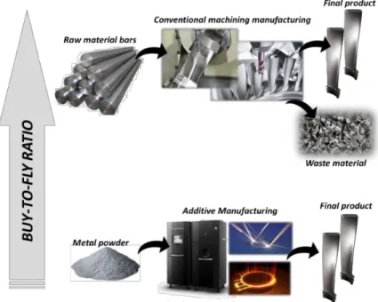
The growing interest in the opportunity of increasing the production rate and introducing new functional products in the aerospace industries is becoming significant. The possibility to produce geometrically complex products without operating numerous manufacturing steps is attracting both academia and industry attention. In fact, these new design techniques bring new products with higher performance, reducing the buy-to-fly ratio and consequently, the waste of material. Therefore, the Additive Manufacturing (AM) techniques are becoming the protagonists in this last decade, especially in the production of parts made by difficult-to-cut materials. However, the AMed products, although they show higher complex shapes that are impossible to achieve by the conventional subtractive processes, post-process treatments are still necessary to improve their surface quality. Nowadays, the research, in order to improve the mechanical properties of the AM products affected by external (poor surface roughness) and internal defects (voids and pores), is developing specific thermal, mechanical and chemical treatments. On the other side, the reduction of production time and the possibility to produce aircraft structural components (thin geometry) are also important. Indeed, the incorrect manufacturing process parameters usually lead to the production of parts with inaccurate tolerances or distorted geometry, especially when aluminum alloys are employed, compromising their mechanical performances. In the contests previously mentioned, the surface integrity plays a key role because it permits to understand the overall quality of the products depending on the process parameters and manufacturing strategies adopted. In aerospace fields the designed components must satisfy high quality requirements in safety/fatigue performance, thus the knowledge of the effects of metallurgical modifications induced by manufacturing processes is very important. Therefore, the produced components can be improved in terms of performance and mechanical resistance just improving the surface integrity, hence optimizing the manufacturing process.
The scope of this Ph.D. thesis is to evaluate the machinability and study the surface integrity of
the materials used in aerospace applications.
In particular, the main objectives are:
to investigate the machinability and study the surface integrity of the Ti6Al4V titanium alloy parts additively manufactured after semi-finishing machining processes at different cutting parameters and cooling strategies (dry and cryogenic);
to investigate the machinability and study the surface integrity of the 7075-T6 aluminum alloy used to produce structural aircraft parts performing the high speed machining process at different cutting parameters and cooling strategies (dry and cryogenic);
to employ a severe plastic deformation (Equal Channel Angular Pressing) process to better understand the physical reasons of the metallurgical changes during severe plastic deformations induced by machining on aluminum alloy;
to define the mechanical behavior flow stress of the additively manufactured titanium parts in order to simulate the semi-finishing machining operations;
to develop a physically-based material behavior model of the aluminum alloy to predict the metallurgical transformation induced by high speed turning operation at different cutting parameters and cooling conditions;
to describe the physical reasons of the microstructural variations and to understand the hardening or softening governing phenomena;
to predict the main fundamental variables such as cutting forces and temperature and to describe the surface integrity in terms of microstructural deformed shapes and hardness changes;
11
Abstract
(lingua italiana)
Oggigiorno, il crescente interesse da parte delle industrie aerospaziali sulle opportunità di poter aumentare il tasso di produzione così come l’introduzione sul mercato di prodotti performanti è significativo. Infatti, la possibilità di produrre componenti meccanici dalle geometrie particolarmente complesse senza dover ricorrere a numerose operazioni manifatturiere sta attirando l’attenzione della comunità scientifica e delle aziende. Le recenti metodologie di progettazione permettono di produrre componenti sempre più performanti riducendo allo stesso tempo il buy-to-fly ratio e conseguentemente gli sfridi di materiale. Pertanto, in questa ultima decade le tecniche di manifattura additiva (AM) stanno diventando le protagoniste soprattutto nella realizzazione di componenti caratterizzati da materiali difficili da lavorare alle macchine utensili quali le leghe di titanio e a base nickel. Tuttavia questi manufatti, sebbene posseggono geometrie molto complesse e funzionali difficilmente realizzabili con i classici processi sottrattivi di materiale, necessitano di successivi trattamenti per migliorarne la qualità superficiale. Oggigiorno, il cuore ricerca industriale in campo aeronautico è anche impegnato nello sviluppo di nuove tecniche meccaniche, termiche e chimiche per trattare i manufatti realizzati con tecniche additive in modo da ridurne le difettosità superficiali (scarsa rugosità superficiale) e interne (vuoti e pori) in modo da migliorarne le performance meccaniche. D’altra parte, la ricerca mira anche a raggiungere ulteriori obiettivi quali la riduzione dei tempi ciclo di produzione o la possibilità di produrre componenti di piccolo spessore sempre più performanti per applicazioni in campo aeronautico. Difatti, questi ultimi vengono principalmente realizzati tramite processi di sottrazione di materiale e pertanto i parametri di processo giocano un ruolo fondamentale nell’ottenimento di prodotti di elevata qualità. Ad ogni modo, è chiaro che l’integrità superficiale rappresenta il fattore di maggior rilievo in quanto permette di stimare in generale la qualità del prodotto finito in funzione della strategia di manifattura definita. Nelle applicazioni aeronautiche i prodotti devono possedere un’elevata accuratezza dimensionale ed elevate proprietà meccaniche, pertanto conoscere gli effetti dei cambiamenti di natura metallurgica indotte dai processi manifatturieri quali l’asportazione di materiale è oltremodo importante. Di conseguenza, le proprietà meccaniche dei componenti realizzati possono essere migliorate migliorando l’integrità superficiale, ovvero ottimizzando il processo manifatturiero.
Lo scopo di questa tesi di Dottorato è studiare la lavorabilità alle macchine utensili e l’integrità
superficiale di manufatti realizzati con materiali principalmente utilizzati in ambito aeronautico.
Nel dettaglio, i principali obiettivi sono:
investigare la lavorabilità alle macchine utensili e studiare l’integrità superficiale a valle dei processi di semi-finitura (in condizioni di lavorazione a secco e criogeniche) della lega di titanio
Ti6Al4V realizzata mediante tecniche additive;
investigare la lavorabilità alle macchine utensili e studiare l’integrità superficiale a valle dei processi di taglio ad alta velocità (in condizioni di lavorazione a secco e criogeniche) della lega di alluminio 7075-T6;
impiegare un processo di deformazione plastica severa (Equal Channel Angular Pressing) per investigare la natura dei fenomeni metallurgici che si innescano durante tali processi e quelli in cui viene asportato materiale tramite operazioni di taglio;
sviluppare un modello che descrive il comportamento meccanico della lega di titanio durante il processo di semi-finitura;
sviluppare un modello fisico che descriva il comportamento meccanico della lega di alluminio esaminata durante i processi di taglio ad elevata velocità;
Prevedere le principali variabili di interesse industriale quali forze di taglio e temperature, descrivere l’integrità superficiale attraverso la previsione di cambiamenti metallurgici e delle proprietà meccaniche quali la microstruttura e capire i fenomeni che governano l’incrudimento o il softening.
13
Acknowledgments
I want to express a sincere gratitude to my supervisor Prof. Domenico Umbrello for giving me the possibility to work in his research group. His continuous help, positive encouragement throughout these years were a strong support and inspiration that allowed me to reach the main goals and present the main outcomes at International Conferences.
I would also like to express my gratitude to Dr. Ing. Giovanna Rotella for her valuable support during the experimental activities in laboratory and for helping me with the very long measurement procedures. Her time spent in helping and guiding me was enormously useful to improve my research skills.
I also thank Professor Fortunato Crea and Dr. Ing. Sebastiano Candamano for their help and strong support during the metallurgical analysis through SEM and XRD techniques.
I am grateful to Professor Stefania Bruschi and her research group from the University of Padova for their valuable contribution in sharing and performing the experimental tests on additively manufactured materials. I am also very grateful to Dr. Ing. Alberto Bordin for having continuously inspired and motivated me during my research activities, especially at the Conferences and for the strong friendship established.
I special thanks goes to Dr. Ing. Antonio Rotella who shared with me all the hardest moments of the academic carrier. I am grateful for his sincere friendship, which always gave me the right motivation to overcome every problem. A special thank goes also to all my friends that made these three years less stressful.
I would also like to express a sincere gratitude to Professor Volker Schulze and the research team of WBK of the Karlsruhe Institute of Technology for allowing me to spend a considerable part of my Ph.D. in their Institute. During the year spent in Germany, He guided me to improve and develop new research skills.
I would like also to express my thankfulness to Ing. Eric Segebade for having guided and motivated me during the activity researches in developing the experimental and numerical activities.
Last but not the least, I want to express my infinite gratitude to my parents and my family for their fundamental support that always helped me to achieve important goals and make the right decisions. Finally, a special thought goes to Martina, her special emotional support always contributed to reach important goals in this period of my life.
C
HAPTER
I
Stano Imbrogno
14
C
HAPTER
I
Introduction
The overall quality of a component, its mechanical performance and reliability during all its life cycle depends on several characteristics. The engineer involved in the design of new parts has to face the structural computations in order to guarantee the functionality of the products that usually operate under complex loading conditions. The choice of the material plays an important role in satisfying the requirements and usually it makes the difference between failed and not failed products. Consequently, the importance of materials science and technology in engineering advanced fields, such as aerospace, cannot be overstated. Several structural parts, mechanical components and joining elements constitute the fundamental frame of an aircraft. Furthermore, the materials used in airframe structures and in jet engine components are crucial to the successful design, construction, certification, operation and maintenance of the aircraft (Figure 1). Materials have an impact through the entire life cycle of aircraft, from the initial design phase to manufacture and certification of the aircraft, to flight operations and maintenance and, finally, to disposal at the end-of-life (Mouritz 2012).
C
HAPTER
I
Stano Imbrogno15
Focusing on engines and structural parts of the aircrafts, these require materials that are lightweight, high strength, damage tolerant, high temperature strength, oxidation and corrosion resistant with robust and repeatable mechanical properties. These materials can be readily manufactured into components that are inspectable to ensure the required level of quality and mechanical capability. These requirements are also bounded by the absolute need for lowest possible cost and greatest possible availability (Ott et al. 2010). The main groups of materials used in aerospace structures are aluminum alloys, titanium alloys, steels and composites. In addition to these materials, nickel-based alloys are important structural materials for jet engine applications. Many other materials are also used in aircraft: copper for electrical wiring; semiconductors for electronic devices; synthetic fabrics for seating and other furnishing. The structural and mechanical metal components are essentially produced by manufacturing processes such as machining. However, nowadays the innovative processes, namely additive manufacturing, allow to produce a part simply adding melted material layer-upon-layer, avoiding to remove material but adding it where it is required. Although these processes are able to produce components with very complex shape and geometrically close to the final product (near-net-to-shape), there are some drawbacks related to the production volume as well as the tolerance and surface quality. Due to the high requirements safety/fatigue performance of the aerospace components, the additively produced parts still require secondary manufacturing steps (semi-finishing processes) in order to achieve the surface quality required and match the geometric designed tolerances (Bordin et al. 2015, Bordin et al. 2014, Gibson et al. 2010). In literature, the titanium alloys produced by AM technologies were mechanically characterized and the outcomes clearly showed different mechanical response if compared with the wrought titanium alloy commonly used. Consequently, the machinability is expected to be different from that investigated by several researchers. A part of this Ph.D. thesis aims to fill this lack of knowledge investigating the machinability of AMed titanium alloy under semi-finishing condition in order to define the surface integrity varying the cooling conditions and cutting parameters (Figure 2). The choice to adopt different cooling strategies, in particular the cryogenic fluid, is because of the positive effects of coolants when low thermal conductivity difficult-to-cut material are machined (Jawahir et al. 2016, Grzesik et al. 2012, Bermingham et al. 2011, Hong 2006). As previously mentioned the aircraft is also characterized by structural and joining components that are usually realized with high performance aluminum alloys (7xxx and 2xxx series coupled with T3 or T6 treatments). Considering the structural components, the aircraft industries are attracted by the possibility to manufacture the aluminum alloy by high speed machining conditions. The advantages compared with the conventional machining are numerous: tremendous reduction of production time, lower cutting forces due to the increase of thermally induced ductility of the material , possibility to reach better tolerances, reduction of the number of parts that need to be assembled (Campbel 2008). Moreover, Chen et al. 2017 highlighted the formation of nanograins during high speed machining of aluminum 7xxx series and the positive effects on mechanical response due to the formation of subsurface nanograins layers. No comprehensive researches are available on high speed turning of the aluminum alloy 7075-T6 under cryogenic conditions. The delivering of liquid nitrogen during machining of aluminum alloy was observed to positively affect the material in terms of mechanical properties due to its ability to preserve the recrystallized grains and prevent their growth (Rotella et al. 2013). Consequently, the mainly applied structural material aluminum alloy 7075-T6 under high speed machining conditions was investigated in order to assess the machinability level and to investigate how the high removal rate affects the surface integrity of the machined parts (Figure 2). The high performance aluminum alloys are also employed to produce rivets and joining components to link and assembly some parts of the aircraft structures (de Rijck et al. 2007). The fatigue strength of these mechanical joining elements plays a key role during the thousand hours of work accomplished by the aircraft during its lifetime; therefore, the mechanical properties of the selected materials are extremely important. Chan 2010 demonstrated that the microstructural and metallurgical changes drastically affect the fatigue life and, in particular, the grain refinement leads to positive effect increasing fatigue strength.
C
HAPTER
I
Stano Imbrogno16
In literature, there are a certain number of processes known as severe plastic deformation (SPD) that lead to an important microstructural refinement and consequently an increment of the work hardening of the processed material. In this Ph.D. thesis, the process known as ECAP (Equal Channel Angular Pressing) was chosen as a SPD process to study the microstructural changes of the aluminum alloy and to find some correlations with the metallurgical variations induced by machining operations. The aim of this research activity is to define new techniques in order to investigate the microstructural modifications when high thermo-mechanical loads are involved during the material forming. From the literature analysis, most of the experimental activities, in which ECAP is used, are designed to induce ultra or nano crystals formations to produce high performance materials. This thesis aims to discover a new scientific application of this SPD process to understand and study the evolution of the metallurgical changes in the deformed material. Subsequently, these phenomena could be modeled and used to predict the microstructural variation in the machining simulation once the links between the deformation mechanisms and material changes are assessed (Figure 2).
C
HAPTER
I
Stano Imbrogno17
1.1. Research objectives
The literature review has highlighted the increasing trends in researching innovative high performance materials as well as new production processes of aerospace components (engine, structural and joining parts). The more complex geometry of the newest produced parts of the aircraft engine: blades, valves, stator/rotor components produced by the innovative additive manufacturing techniques demonstrated to be stronger than the same materials produced by conventional subtractive processes. Moreover, the materials used to produce engine parts (e.g. titanium alloy Ti6Al4V ) are extremely difficult to machine due to their higher thermo-mechanical performance, therefore the AM is becoming important. The differences in mechanical performances between the machined and the AMed parts are mainly due to their different metallurgical aspects. However, the geometrical tolerances and surface quality obtained on the additively manufactured parts do not satisfy the requirements defined during the designing phase. Therefore, semi-finishing machining operations are still necessary to improve the geometry, reduce the distortions and the roughness, improving the surface quality. The literature analysis showed a lack of knowledge about the machinability strategy to improve the surface quality of these new materials produced via AM. Further investigations are also necessary to assess the mechanical behavior of AMed parts under machining conditions. The literature analysis has also highlighted the importance to improve the production rate through the increment of the cutting speed to extreme values (high speed machining conditions), when aircraft structural parts made by aluminum alloy are produced. In fact, the aluminum alloy particularly shows a refining of the microstructure, more evident at high plastic deformation rate, and this usually leads to enhancement of the mechanical properties and the fatigue strength. The presence of finer grain layers on the produced components leads to extend their duration during the operative conditions. The aluminum alloy AA7075-T6 has been usually employed in producing structural aircraft parts, such as wings ribs, fuselages etc. and the parts are usually produced by machining processes. In literature, interesting results in terms of grain refinement and improved mechanical properties induced by machining on this kind of alloy are reported but the process parameters used (cutting speed lower than 800m/min) did not permit to achieve high production rates. The aluminum series (7xxx) is also employed in producing joining parts such as rivets. Several research articles based on applications of severe plastic deformation processes to the 7075-T6 alloy are reported but no comparison studies with the metallurgical changes machining induced are provided. In detail, the evolution of the thermo-mechanical loads induced by the SPD processes, such as ECAP, and their effects in metallurgical changes are not employed to investigate the same phenomena that occur during the machining processes. Taking into account the main lacks of knowledge highlighted by the literature analysis, the main objectives of this research are:
to investigate the machinability and study the surface integrity of the additively manufactured titanium (Ti6Al4V alloy) machined parts after semi-finishing machining processes at different cutting parameters and cooling strategies;
to investigate the machinability and study the surface integrity of the aluminum alloy
(7075-T6 ) used to produce structural aircraft parts performing the high speed machining
conditions at different cutting speed and cooling strategies;
to employ and adapt the ECAP process to better understand the physical reasons of the metallurgical changes during severe plastic deformation induced by machining on aluminum alloy;
to define the mechanical behavior flow stress in order to simulate the semi-finishing machining operations on the additively manufactured titanium parts To perform further investigations to assess the surface integrity in terms of microstructure deformation shape and hardness changes;
to develop a physically-based model of aluminum alloy to simulate high speed turning operation at different cutting parameters and cooling conditions;
to describe the physical reasons of the microstructural variations and to understand the hardening or softening governing phenomena;
C
HAPTER
I
Stano Imbrogno18
1.2. Dissertation outline
The schematic representation of this Ph.D. thesis is reported in Figure 3. The flow chart represents the organization of the analyzed topics (state-of-the-art), the experimental and numerical activities that are discussed in this work.
Chapter II is a literature review that aims to analyze and compare the new advanced production process
techniques, namely the Additive Manufacturing, and the conventional material removal processes used to produce the aircraft components (in detail structural and engine components). Further attention has been paid in the manufacturing process used to realize aircraft structural parts. The analysis focuses on the new challenges, advantages and drawbacks introduced by these new techniques and the efforts done to date in order to overcome the problems and to improve the quality of the produced products. In detail, two materials mainly used in aerospace field, titanium and aluminum alloy, have been considered in this analysis due to the high industrial and scientific interest.
Chapter III describes the experimental activity devoted to the analysis of the machinability of the titanium
alloy Ti6Al4V produced by AM processes. In particular, the main fundamental variables such as cutting forces and temperatures as well as the surface integrity have been assessed comparing these results to the ones obtained by machining the wrought titanium alloy. The innovative cooling technique, namely cryogenic fluid delivery, has been also investigated in order to analyze its effect on the machinability and surface integrity as well. Moreover, a final discussion that relates the obtained results with the mechanical performance of the material is also reported.
In Chapter IV, the experimental investigation on the aluminum alloy 7075-T6 under high speed machining operation and SPD process is reported. In detail, the machinability and the surface integrity of the aluminum alloy at different cutting parameters and cooling conditions have been assessed. Furthermore, a SPD process (ECAP) on the 7075-T6 alloy has been carried out to understand the metallurgical changes and to find possible links between the microstructural variations induced by machining and SPD processes.
Chapter V reports the numerical study of the titanium and aluminum alloy subjected to machining
operation. In detail, the mechanical behavior of the titanium alloy post AM process has been defined and implemented into FE software to simulate the machining process. Subsequently, the metallurgical changes have been modelled and implemented to study their evolution during the cutting process. The mechanical behavior of the aluminum alloy, due to the machining processes and the several physical phenomena involved into the deformation process, has been described by a customized physics based model. Subsequently, this model has been implemented in a FE software in order to simulate and study the metallurgical changes such as dislocation density and grain sizes during the machining process.
Finally, the conclusion remarks summarizes the obtained results and highlights the probable future improvements that should be done by future works.
C
HAP
T
ER
I
Sta no I mbr og no 19 Figure 3: Fl ow c hart o f the Ph .D . the sis .
C
HAPTER
II
Stano Imbrogno20
C
HAPTER
II
Advanced and conventional manufacturing processes of
aerospace metal components
This chapter provides a brief literature review on aerospace materials focusing on the metal ones (titanium and aluminum alloys) and in particular, the alloys employed to produce engine, structural and joining parts. Subsequently, a brief state-of-the-art of the manufacturing processes used to build the aerospace mechanical components is also reported. The new outcomes and challenges introduced by the conventional and advanced manufacturing processes in fabricating the innovative mechanical components are highlighted. A detailed state-of-the-art on metallurgical aspects coupled with thermo-mechanical properties of the analyzed metal materials when manufactured are described and used in Chapter , Chapter IV and Chapter V as a support in understanding the experimental results and build up new material behavior constitutive models.
2.1 Aerospace materials for engine, structural and engine components
The aircraft structural design is driven by two design philosophies namely fail-safe and safe-life. Fail-safe design (denoted also as damage tolerant design) ensures that between two consecutive inspection intervals the overall structural integrity and function are not affected by failure or damage of some parts of the structure. Safe-life design implies that the structure and its components will function without any failure during the prescribed lifetimes of the components. It is clear that the design technique of structural or engine parts have in common the word “safe”. In general, the typical functions of a structural component are primarily to resist and transmit the forces, while the engine parts have to resist to high pressure and temperature and drastic operative conditions in total “safe”. Besides strength and general damage tolerance, aircraft structures must also be resistant to degradation from fatigue, corrosion, and stress corrosion; and in elevated temperature applications the materials must be resistant to creep and thermal instability. To respect the design requirements and satisfy the “safe” conditions, not only the geometry but also the selection of the best material for an aircraft structure or engine component is an important task for the aerospace engineer. The success or failure of any new aircraft is partly dependent on using the most suitable materials. The cost, flight performance, safety, operating life and environmental impact from engine emissions of aircraft is also dependent on the types of materials that aerospace engineers choose to use in the airframe and engines. Generally, the aerospace materials must be light, stiff, strong, damage tolerant and durable. These requirements aim to increase the airframe durability that is one of the main target for commercial and military aircraft production enterprises. However, most of the materials lack one or more of the essential properties that are strongly required by the aerospace structures and engine applications. Consequently, there is always a continuing demand for high-quality materials and metal alloys with closely controlled chemistries, cleanliness and homogeneity in mechanical response and statistically controlled reproducibility of the thermo-mechanical properties (Prasad and Wanhill 2017 – Volume 1). Other demands on aerospace materials are emerging as important future issues. These demands include the use of renewable materials produced with environmentally friendly processes and materials that can be fully recycled at the end of the aircraft life. Sustainable materials that have little or no impact on the environment when produced, and the reduction of the environmental impact of the aircraft by lowering fuel burn (usually through reduced weight), will become more important in the future (Prasad and Wanhill 2017 – Volume 2, Mouritz 2012).
As an example, the long-term strategic objectives of “Flightpath 2050” foresee the 75% reduction in CO2 per passenger kilometer, the 90% reduction in NOx emissions and the 65% reduction in noise.
C
HAPTER
II
Stano Imbrogno21
This means the lightweight designs and new advanced materials on airframes and engines, advanced aerodynamic performances, advanced turbine materials for aero engines (disc and blades) (M’ Saoubi et al. 2015). Consequently, as showed by Figure 4, the fundamental requirements previously explained are satisfied by several class of materials such as aluminum alloys, titanium alloys, steels and composites. In addition to these materials, nickel-based alloys are important structural materials for jet engines. Many other materials are also used in aircraft: copper for electrical wiring; semiconductors for electronic devices; synthetic fabrics for seating and other furnishing.
Figure 4: Materials and their weight percentages used in the airframes of civilian and military aircrafts (adapted from Mouritz 2012).
Taking into account the group of materials referred to aluminum and titanium alloys; these are mainly used to produce the mechanical and structural components of the functional groups showed in Figure 5.
C
HAPTER
II
Stano Imbrogno22
As showed by Figure 4, although the presence of the composite material is constantly growing in aerospace field, the titanium and aluminum alloy usually represent the highest percentage of the material employed. The trends showed by Figure 6 suggest an increasing tendency to employ titanium alloy in military sector as well as a constant improvement of the mechanical properties of the aluminum alloys in order to increase their performance in aerospace applications. Therefore, due to the high interests in improving the mechanical performances of the aluminum and the increasing demand of titanium in aerospace applications, the material investigated by this Ph.D. thesis are in detail the aluminum alloy 7075-T6 and the titanium alloy
Ti6Al4V.
Figure 6: a) Yield strength of aluminum alloys and the year of introduction into civils transport services; b) Titanium content % used in military and civils transport aircrafts (adapted from Mouritz 2012).
The structural and joining components are mainly produced in aluminum alloy. This latter accounts for 60-80% of the airframe weight of most modern aircraft and this result is justified by its specific weight that make this material the lightest metal, being about 2.5 times lighter than steel. In addition, aluminum can be easily fabricated into thin skin panels and readily machined into spars, stiffeners and beams for the fuselage and wings. Around 400000 tons of aluminum each year are used in building military and civil aircrafts. Aluminum is used in the main structural sections of the Boeing B747 and B777, including the wings, fuselage and empennage (tail assembly). The fuselage of the civilian aircrafts is characterized by a semi-monocoque structure. A semi-monocoque fuselage consists of a thin shell stiffened in the longitudinal direction with stringers and longerons and supported in the radial direction using transverse frames or rings (Figure 7a). The strength of a semi-monocoque fuselage depends mainly on the longitudinal stringers (longerons), frames and pressure bulkhead. The skin carries the cabin pressure (tension) and shear loads, the longitudinal stringers carry the longitudinal tension and compression loads, and circumferential frames maintain the fuselage shape and redistribute loads into the airframe. During the flight, the upward loading of wings coupled with the tail plane loads usually generates a bending stress along the fuselage. The lower part of the fuselage experiences a compressive stress whereas the upper fuselage (called the crown) is subject to tension. Therefore, it is possible to understand that the structural parts experience very complex loads combinations in critic environmental conditions. Concerning the wings (Figure 7b), the main function is to pick up the air loads to maintain flight and transmit the load to the fuselage (via wing-box and wing connections). In military combat aircrafts the fluctuating loads are generally higher than commercial aircraft owing to the need for frequent and fast maneuvering. These fluctuating loads can induce fatigue damage. Therefore, the necessity to research high performance materials with high fatigue strength to resist damage and failure from fluctuating loads and turbulence is an important requirement as well. Furthermore, it is known that fatigue damage does not occur in compression, and therefore the lower (tension) and upper (compression) wing surfaces have different material requirements. For this reason, several materials are also used in a single aircraft wing.
C
HAPTER
II
Stano Imbrogno23
For example, subsonic aircraft wings have traditionally been made using two types of aluminum alloys: high compressive strength alloy (such as 2024 Al ) for the upper wing surface and high tensile strength alloy (e.g. 7075 Al ) for the lower surface. It is imperative use high performance and lightweight materials to produce wings because they account the 20-25% of the structural weight of an aircraft.
Figure 7: a) Boeing 787 fuselage under construction; b) wing and its internal structures made by wing ribs; c) Aluminum alloys used on Boeing 777 (adapted from Starke and Staley 1996).
In Figure 7c, the typical aluminum alloys used to produce various parts of the Boeing 777 are reported. Referring to Figure 4, the second most important material used in building aircrafts is the titanium alloy. This percentage is mainly referred to the material used to produce mechanical components of the engines, especially for aircraft intended to civilian transportation. This material finds also structural and covering applications in military aircraft as showed by Figure 6b (in this latter the percentage is higher if compared with the civilian aircraft). The material used in jet engines are subjected to the most arduous working temperature in an aircraft. In fact, the turbines compress the air to high pressure and this air is then heated to extreme temperature by burning fuel to produce hot, high-pressure gases which are expelled from the engine exhaust thus propelling the aircraft forward. The engine materials must perform for long periods under high temperatures and stresses while exposed to hot corrosive and oxidizing gases generated by the burning fuel. Jet engine materials must possess high tensile strength, toughness, fatigue strength and creep resistance together with excellent resistance against corrosion and oxidation at high temperature (Mouritz 2012). An example of different materials applied into the aerospace jet engine depending on the temperature working conditions is showed in Figure 8.
Figure 8: a) blades material at different temperature operative conditions into a representative aerospace jet engine; b) economy of weight achieved in the case of using titanium for engines: 1, large-size; 2, medium-size; 3, small-size (Rolls-Royce Trent 700).
C
HAPTER
II
Stano Imbrogno24
Generally, the titanium and nickel alloys are preferred due to their ability to meet higher strength and corrosion resistance required at high temperature.
Titanium alloys, such as Ti6Al4V, are mainly used in fan and compressor assemblies – disks, blades, guides, spacer rings, engine body, various engine-body parts, air collectors, and other items. Moreover, in military applications, the titanium alloy is also used in the region of the aircraft in which the temperature reaches values up to 300-350 °C. Titanium is used as a replacement material for steel in landing gear to eliminate the problems of corrosion and hydrogen embrittlement as well as to achieve a significant weight saving. The use of titanium alloys in aircraft-engines instead of steel reduces the weight of components by 30-40% leading considerable benefits in terms of reduction of fuel consumption (Mouritz 2012, Moiseyev 2006). Moreover, titanium has the ability to form a thin oxide surface layer, which is resistant and impervious to most corrosive agents and which provides excellent corrosion resistance.
The work materials investigated in this Ph.D. thesis are the most common used aluminum and titanium alloy; in detail the AA7075-T6 and the Ti6Al4V respectively. The metallurgical aspects of these materials permit to understand their properties that make them suitable for aerospace applications.
2.1.1 Titanium alloy
– Ti6Al4V
Titanium was discovered in 1790 but not purified until the early 1900s. Nowadays it has the accumulated experience of some 50 years of modern industrial practice and design application to support its use (Donachie 2000). Titanium is the ninth most-abundant element on the planet and the fourth most-abundant structural metal. Mineral sources of titanium are rutile, ilmenite and leucoxene, an alteration product of ilmenite (Figure 9).
Figure 9: a) Rutile, b) Ilmenite.
A metallurgical property of titanium alloys that is important in their use in aircraft is allotropy, which is defined as different physical forms of the same material that are chemically very similar. Many metals, including the aluminum, magnesium and nickel alloys used in aircraft, can only occur in one crystalline phase at 20 °C. For instance, aluminum can only have a face-centered-cubic (FCC) crystal structure at room temperature, and no other. As another example, the crystal structure of magnesium is always hexagonal close packed (HCP) at 20 °C. Titanium alloys, on the other hand, can have two elemental crystal structures namely hexagonal-close-packed (HCP) crystal structure, which is known as alpha (α-Ti), and a body-centered-cubic (BCC) structure, which is called beta (β-Ti), at room temperature (Figure 10).
C
HAPTER
II
Stano Imbrogno25
Figure 10: Appearance of crystal structures of titanium at atomic level (Donachie 2000).
The single cubic structure is found only at high temperatures, unless the titanium is alloyed with other elements to maintain the cubic structure at lower temperatures. The alpha and beta “structures”— sometimes called systems or types are the basis for the generally accepted four classes of titanium alloys: alpha, near-alpha, alpha-beta, and beta. These categories denote the general type of microstructure after processing (microstructure refers to the phases and grain structure present in a metallic component). Alloying elements can be generally classified as α or β stabilizer as reported in Table 1. Alpha stabilizers as aluminum or oxygen increase the temperature at which the alpha phase is stable. On the other hand, Vanadium or Molybdenum which are beta stabilizer allow the beta phase to be stable at lower temperatures (Donachie 2000).
Table 1: Alloying titanium elements and their effects (Donachie 2000).
Alloying element Range [wt%] Effect on structure
Aluminum 2 to 7 Alpha stabilizer
Tin 2 to 6 Alpha stabilizer
Vanadium 2 to 20 Beta stabilizer Molybdenum 2 to 20 Beta stabilizer Chromium 2 to 12 Beta stabilizer
Cooper 2 to 6 Beta stabilizer
Zirconium 2 to 8 Alpha and beta strengthening Silicon 0,2 to 1 Improves creep resistance
The Ti6Al4V (α+β category) is the most widely used in aerospace industries. Ti6Al4V alloy contains 6 wt% Aluminum stabilizing the α phase and 4 wt% Vanadium which stabilizes the β phase. The equilibrium at room temperature consists of α phase (HCP) in a retained β phase (BCC). As it is possible to see in Figure 11, the transformation temperature from alpha-plus-beta or from alpha to all beta is known as the beta transus temperature (995 °C). The beta transus is defined as the lowest equilibrium temperature at which the material is 100% beta. Below the beta transus, titanium is a mixture of alpha-plus-beta if the material contains some beta stabilizers; otherwise it is all alpha if it contains limited or no beta stabilizers. The beta transus is important because processing and heat treatment often are carried out with reference to some incremental temperature above or below the beta transus. In relation to the chemistry of the selected alloy, the microstructure is produced depending on the heat treatment selected (Lütjering and Williams 2007). Taking into account that the Ti6Al4V is an α+β alloy, the microstructure that results at room temperature is a function of the way in which the transformation of beta to alpha phase occurs. For the commercial Ti6Al4V alloy, there are some commonly used heat treatments that produce different microstructures. Figure 11 shows some microstructures formed during solution temperature and cooling rate variations. The microstructure formed from beta region, depending on the cooling rate can evolve in equiaxed or acicular also known as Widmanstätten (Figure 11).
C
HAPTER
II
Stano Imbrogno26
This latter microstructure consists of parallel plates of α delineated by the β phase between them. Depending on the quenching temperature and chemistry of the alloy, different types of martensite can form. These are designated α prime and α double prime.
Figure 11: Effect of cooling rate on the microstructure of an alpha-beta alloy (Ti6Al4V ); (a) α' + β; prior beta grain boundaries; (b) Primary α and α' + β; (c) Primary α and α' + β; (d) Primary α and metastable β; (e) Acicular α + β; prior beta grain boundaries; (f) Primary α and acicular α + β; (g) Primary α and acicular α + β; (h) Primary α and β; (i) Plate-like α + β; prior grain boundaries; (j) Equiaxed α and intergranular β; (k) Equiaxed α and intergranular β; (l) Equiaxed α and intergranular β (adapted from Donachie 2000).
There are some significant facts and / or important benefits offered by titanium alloys that illustrate the basis for the widespread use of titanium today:
• The density of titanium is only about 60% than that of steel or nickel-base superalloys.
• The tensile strength (as an alloy) of titanium can be comparable to that lower-strength martensitic stainless and is better than that of austenitic or ferritic stainless.
• The commercial alloys of titanium are useful at temperature to about 538 °C to 595 °C, dependent on composition.
• Titanium is exceptionally corrosion resistant. It often exceeds the resistance of stainless steel in most environment, and it has outstanding corrosion resistance in the human body.
• Titanium can be forged or wrought by standard techniques.
• Titanium is castable and the investment cast titanium alloy structures have a lower cost than conventional forged / wrought fabricated titanium alloy structures.
• Titanium is available in a wide variety of types and forms.
Due to its good compromise between mechanical resistance and tenacity, together with its low density and excellent corrosion resistance, Ti6Al4V titanium alloy is often used in two areas of application: corrosion-resistant service and strength-efficient structures that normally are representative of the aerospace field.