Hybrid nanostructured fillers for polymer
electrolytes in the PEM Fuel Cells
Kristina Angjeli
_________________________________________
University of Calabria
Doctorate school Bernardino Telesio Department of Chemistry 2012 ______________________________________________________________________________________________
PREFAZIONE
Le celle a combustibile a idrogeno e metanolo diretto (DHFC/DMFC) che utilizzano come elettrolita una membrana di tipo PEM costituiscono dei sistemi per la generazione di potenza non inquinanti adatti per applicazioni su veicolo elettrico/ibrido o per applicazioni portatili, in virtù della loro elevata efficienza di conversione energetica (~50%) ed emissioni zero.
Tuttavia, i principali ostacoli alla commercializzazione su vasta scala delle PEMFC sono l’alto costo, la bassa conduttività protonica alle basse umidità e le scarse proprietà meccaniche a temperature superiori ai 130°C. Per superare queste difficoltà, sono allo studio membrane nanocomposite innovative basate su polimeri perfluorosulfonati-acidi (PFSA) come il Nafion.
In questo lavoro di dottorato membrane ibride nanocomposite sono state preparate a partire da tre tre classi di filler stratificati e nano strutturati: (i) argille smectite (sintetici e naturali), (ii) ossido di grafene (GO), e (iii) idrossidi doppi strati (LDHs).
Questi materiali opportunamente sintetizzati e funzionalizzati sono stati caratterizzati da una combinazione di diffrazione di raggi X, spettroscopia FTIR, analisi termica (DTA / TGA), Raman, microscopia elettronica a scansione (SEM) e analisi dinamica meccanica.
Uno degli obiettivi principali in questo lavoro è stato quello di coniugare un'intensa attività di ricerca di base, al fine di comprendere i meccanismi molecolari alla base della conduzione ionica in sistemi così complessi, con la progettazione, la sintesi e la caratterizzazione di nuovi nano compositi con opportuni requisiti. A tal fine, uno studio approfondito delle proprietà di trasporto dell'acqua confinata nelle membrane elettrolitiche è stato effettuato mediante metodi NMR per comprendere la dinamica molecolare e i meccanismi alla base della conduzione ionica all’interno delle membrane composite e come questi sono influenzati dalla struttura polimerica e dai filler dispersi.
This thesis is dedicated to my family
Hybrid nanostructured fillers for polymer
electrolytes in the PEM Fuel Cells
© Kristina Angjeli 2012
PhD Dissertation
Laboratory: PC_SM “Mario Terenzi” Department of Chemistry
University of Calabria Ponte P. Bucci, 14D 87036-Rende (CS) Italy
ABSTRACT
The present thesis is focused on the development of novel nancomposite membranes, prepared by the incorporation of two-dimensional inorganic layered structures such as (i) smectite clays (synthetic and natural), (ii) graphene oxide (GO), and (iii) layered double hydroxides (LDHs) with different compositions into the polymer matrix of Nafion, for use as electrolytes in Proton Exchange Membrane fuel cells. The characteristics of the membranes were studied mainly, in terms of transport properties by NMR spectroscopy, in order to study the water dynamics inside the electrolyte membranes. For this purpose the Pulse-Field-Gradient Spin-Echo NMR (PFGSE-NMR) method was employed to obtain a direct measurement of water self-diffusion coefficients on the water-swelled membranes in a wide temperature range (25-140 °C). This technique together with the 1H-NMR spectral analysis and NMR spin-lattice relaxation times (T1) conducted under variable temperature.
Furthermore, both pristine materials (fillers and Nafion) as well as the resulted nanocomposite membranes were characterized by a combination of X-ray diffraction, FTIR spectroscopy, thermal analysis (DTA/TGA), Raman spectroscopies and scanning electronic microscopy (SEM).
LIST OF PAPERS
1. I. Nicotera, A. Enotiadis, K. Angjeli, L. Coppola and D. Gournis
“Evaluation of smectite clays as nanofillers for the synthesis of nanocomposite polymer electrolytes for fuel cell applications”
International Journal of Hydrogen Energy (2012) 37, 6236-6245.
2. I. Nicotera, A. Enotiadis, K. Angjeli, L. Coppola, G. Ranieri, D. Gournis
“Effective improvement of water-retention in nanocomposite membranes using novel organomodified clays as fillers for high temperature PEMFCs”
Journal of Physical Chemistry B (2011) 115, 29, 9087-9097.
3. A. Enotiadis, K. Angjeli, N. Baldino, I. Nicotera, D. Gournis
“Graphene-based Nafion nanocomposite membranes. Enhanced Proton Transport and Water Retention by Novel Organo-Functionalized Graphene Oxide Nanosheets”
Small (2012), 8, 3338-3349. (DOI: 10.1002/smll.201200609)
4. Isabella Nicotera, Kristina Angjeli, Luigi Coppola, Antonino S.Aricò and Vincenzo Baglio. “NMR and Electrochemical investigation of the Transport Properties of Methanol and Water in Nafion and Clay-Nanocomposites Membranes for DMFCs”
Membranes (2012), 2, 325-345.
SUBMITTED PAPER
1 K. Angjeli, I. Nicotera, M. Baikousi, A. Enotiadis, D. Gournis, A. Saccà, E. Passalacqua,
A. Carbone
“Investigation of Layered Double Hydroxide (LDH) Nafion-Based composite membranes for high temperatures PEMFCs”
Submitted to Solid State Ionics.
CONFERENCES PRESENTATIONS
International Conference on Solid State Ionics July 3-8 2011, Warszawa, Poland. Oral presentations “Novel nanocomposite membranes based on organo‐modified graphite oxide for lowhumidity pem fuel cells”, K. Angjeli, A. Enotiadis, I. Nicotera , C. Oliviero, L. Coppola, G.A. Ranieri ,D. Gournis.
Symposium on Porous Materials, 30th June – 1st July 2011, Crete, Greece. Oral presentation “Improvement of water retention on polymer electrolyte membranes using layered structures” A. Enotiadis, K. Angjeli, I. Nicotera and D. Gournis 5th PanHellenic.
9th Conference on Solid State Chemistry 10 September- 15 September 2010 Prague, Czech Republic. Poster presentation “Laponite-clay fuctionalized for nafion nanocomposite membranes in the pem fuel cells applications: water mobility”, K. Angjeli, A. Enotiadis, I. Nicotera , C. Oliviero, L.Coppola, G. A. Ranieri ,D. Gournis.
XXII International Symposium on Polymer Electrolytes 29 August ‐ 3 September 2010, Padova, Italy. Poster presentation “Evaluation of smectite clays as nanofillers for the synthesis of nanocomposite polymer electrolytes for fuell cell applications” I. Nicotera, A. Enotiadis, K. Angjeli, C. Oliviero, L. Coppola, G. A. Ranieri ,D. Gournis.
3rd International CARISMA Conference, 3-5 September 2012 Copenhagen, Denmark. Poster presentation “Inorganic-organic membranes from the short side chain perfluorosulfonic acid ionomer for direct methanol fuel cell.” K. Angjeli, I. Nicotera, D. Jones and J. Roziére.
XXVI International Conference on Solid State Protonic Conductors- SSPC 16- Grenoble (France), 10-14 Sept. 2012. “Investigation of Layered Double Hydroxide (LDH) Nafion-Based composite membranes for high temperatures PEMFCs”. A. Carbone, K. Angjeli, D. Gournis, I. Nicotera, A. Saccà, E. Passalacqua.
CONTENT INDEX
INTRODUCTION 1
1. GENERAL ASPECTS AND APPLICATIONS 4
1.1 HYDROGEN ECONOMY AND FUEL CELLS 4
1.2 HISTORY OF FUEL CELL TECHNOLOGY 5
1.2.1 Types of Fuel Cells 8
1.3 PROTON EXCHANGE MEMBRANE MATERIALS FOR PEMFCS 15
1.3.1 Nafion polymer 18
1.4 PROTON CONDUCTION MECHANISMS IN PEM 26
1.5 HIGH TEMPERATURE PEM FUEL CELLS (HT-PEMFCS) 30
1.5.1 Composite Membranes 32
References 35
2. MATERIALS 38
2.1 CLAYS 38
2.2 GRAPHENE – GRAPHITE OXIDE 42
2.3 LAYERED DOUBLE HYDROXIDE (LDH) 47
References 51
3. EXPERIMENTAL TECNIQUES 53
3.1 NUCLEAR MAGNETIC RESONANCE (NMR) 53
3.1.1 Temperature dependence of T1 and T2 58
3.1.2 NMR PGSE Techniques 60
3.2 SCANNING ELECTRON MICROSCOPY 64
3.3 DYNAMIC MECHANICAL ANALYSIS 66
References 68
4. RESULTS AND DISCUSSION 69
4.1 CLAYS-BASED NANOCOMPOSITES FOR PEMFCS (PAPER I) 70
4.1.2. Water transport properties in clays-based PEM 72 4.2 CLAY-NANOCOMPOSITES FOR DIRECT METHANOL FUEL CELLS (DMFCS)
(PAPER II) 76
4.3 ORGANO-MODIFIED CLAYS FOR HT-PEMFCS (PAPER III) 83
4.3.1 Preparation of organo-modified clay nanofillers 83
4.3.2 Properties of SWy-organoclays nanocomposites 85
4.3.3 Properties of Laponite-organoclays nanocomposites 91
4.4 ORGANO-FUNCTIONALIZED GRAPHENE OXIDE (GO) – BASED
NANOCOMPOSITES MEMBRANES (PAPER IV) 92
4.4.1 Synthesis of organo-modified GO nanofillers 93
4.4.2 Preparation of organo-GO nanocomposites 94
4.4.3 Properties of the organo-GO nanocomposites 96
4.5 LDH-BASED NANOCOMPOSITES FOR PEMFCS (PAPER V) 99
4.5.1 LDH-based nanocomposites by using Nafion 1000 EW as ionomer 99
4.5.2 LDH -- based nanocomposites by using Nafion 1100 EW 101
4.6 AQUIVIONTM-ZRP COMPOSITE MEMBRANES 104
4.6.1 Zirconium Phosphate 105
4.6.2 Preparation of Composite Membrane 106
4.6.3 Structural and Morphological Characterization 108
4.6.4 Physicochemical Characterization and Proton Conductivity 112
References 115
COLCLUSIONS 118
Introduction
The issue of renewable energy is becoming significant due to increasing power demand, instability of the rising oil prices and environmental problems. Among the various renewable energy sources, fuel cell is gaining more popularity due to their higher efficiency, cleanliness and cost-effective supply of power demanded by the consumers.
In the recent scenario, proton exchange membrane fuel cells (PEMFCs) are one of the most promising clean energy technologies. The potential advantages of PEMFCs are related to their possible use in electric and hybrid vehicles or portable apparatuses through (a) the high energy conversion efficiency (~ 50%), (b) the reduced environmental impact for the low CO2 emissions (zero in the case where the primary
fuel is hydrogen) and (c) the flexibility respect to the fuel, in fact, besides hydrogen (DHFC), they can be fed with methanol (DMFC).
The key constituent of a PEMFC is a dense proton-exchange membrane, which is responsible for proton migration from the anode to the cathode. Typically is based on perfluorosulfonic acid (PFSA) polymer membranes, such as Nafion (by Du Pont), which currently represents the most widely used polymer for its unique combination of chemical inertia, mechanical, thermal stability and high proton conductivity; therefore, it constitutes a term of comparison for all new electrolyte materials. Polymer electrolyte fuel cells based upon PFSA membranes have typically been operated in a temperature range between approximately 50 and 90 °C. This temperature range is a compromise between competing factors.
In recent years, increasing interest has been devoted to the development of high temperature proton conducting polymer electrolyte fuel cell systems. In fact, most of the key issues and shortcomings of PEMFC technology, such as water management, CO poisoning, cooling and heat recovery, can be solved or avoided by developing alternative membranes with suitable ionic conductivity and stability up to 120-130 °C. Polymer membranes able to operate above 120 ° C could benefit from both enhanced carbon monoxide (CO) tolerance and improved heat removal. But, the most significant
barrier to running a polymer electrolyte fuel cell at elevated temperatures is maintaining the proton conductivity of the membrane.
For this reason substantial efforts are devoted by the academia and industry to the development of novel fuel cell membrane materials, driven by the need for membranes with improved functionality (e.g., ionic conductivity, robustness) and more cost-efficient polymers.
A number of alternative strategies have been proposed to satisfy these requirements and to maintain membrane conductivity in a dehydrating environment (i.e. elevated temperature and reduced relative humidity). One of these is to integrate hygroscopic materials in the polymer matrix, obtaining nanocomposites membranes. Nanocomposites, that are the object of my doctoral project , generally consist of an ionomer (usually containing acid or superacid -SO3H groups) in which inorganic or
inorgano-organic solid particles are dispersed. The properties of these composite membranes not only depend on the nature of the ionomer and the solid used but also on the amount, homogeneous dispersion, size, and orientation of the solid particles dispersed in the polymeric matrix. Additionally, the introduction of inorganic materials into the polymeric matrix can be considered as a good approach to improve the proton transport, the retention to the swelling and the resistance to the methanol cross-over in DMFC (direct methanol fuel cells) working conditions (membrane in equilibrium with liquid water-methanol mixture).
The work presented in this thesis is the result of a Ph.D. project carried out during a period of about three years from 2009 – 2012, in the Physical Chemistry Soft Matter Laboratory “Mario Terenzi” (PC_SM Mario Terenzi) at the Department of Chemistry in the University of Calabria. The thesis was written as part of the requirements for obtaining the doctor of philosophy degree. Aim of the present thesis is the development of proton conducting nanocomposite membranes based on Nafion polymer, for use as electrolytes in Proton Exchange Membrane fuel cells. The research study focused on the incorporation of two-dimensional inorganic layered structures such as (i) smectite
clays (synthetic and natural), (ii) graphene oxide (GO), prepared by oxidizing
powdered graphite, and (iii) layered double hydroxides (LDHs) with different compositions (various combinations of interlayer anions and molar ratios of divalent to trivalent cations), into the polymer matrix of Nafion for the creation of novel hybrid nanocomposites membranes for operation above 100 ° C. Nafion hybrid membranes,
were synthesized by solution intercalation, while the effect of the solvent, temperature and filler loading were examined in order to determine the optimum conditions for the preparation of highly homogeneous composites.
Water-transport properties inside the membranes were investigated by NMR spectroscopy, including pulsed-field-gradient spin-echo (PFGSE), spectral analysis and spin-lattice relaxation time (T1) conducted under variable temperature. In addition, both pristine materials (fillers and Nafion) as well as the resulted nanocomposite membranes were characterized by a combination of X-ray diffraction, FTIR spectroscopy, thermal analysis (DTA/TGA), Raman spectroscopies, scanning electronic microscopy (SEM) and dynamic mechanical analysis.
The results obtained all these three years have been published in four scientific papers in different international journals. All of the papers are reported in appendices to the end of the thesis. The results obtained using as nanofillers the LDH materials have been divided in two papers, the first is recently submitted in the Solid State Ionics and is also reported in appendix, while the second is in preparation.
During my Ph.D. stage for a period of five months, in the Institute Charles Gerhardt ICGM – AIME, CNRS - University of Montpellier II, in France, under the supervision of Dr. Deborah Jones, the research study focused mainly on the preparation of composite membranes using an alternative polymer to Nafion. In the work presented in this thesis, the short side chain perfluorosulfonic acid ionomeric matrix (Aquivion TM), has been used as template for α-type ZrP inorganic particle growth. The membranes were characterized by measurements of water uptake and dimensional change, determination of proton conductivity as a function of relative humidity, observation of structure by SEM and TEM, 31P NMR spectroscopy, and X-ray diffraction. The differences of the characteristics of the Aquivion TM -ZrP nanocomposite membrane compared to the pure AquivionTM membrane were investigated. The results obtained of this work were presented in a poster at the 3rd International Carisma Conference 2012,
1.1 Hydrogen economy and fuel cells
Energy is one of the most important topics in the 21st century. With the rapid depletion of fossil fuels and increasingly worsened environmental pollution caused by vast fossil-fuel consumption, there is high demand to make efficient use of energy and to seek renewable and clean energy sources that can substitute fossil fuels to enable the sustainable development of our economy and society. Energy storage can be dated back to ancient times and it is quite simple and natural. With the rapid development of modern industries and the durative increase of global population, the rate of electrical energy consumption has dramatically increased and its consumption manner is
diversified. Energy storage becomes even more complex and important, desirable and high-performance energy storage techniques are needed to enable efficient, versatile, and environmentally friendly uses of energy including electricity6. Moreover worldwide reduction of CO2 emission to reduce the risk of climate change (greenhouse
effect) requires a major restructuring of the energy system. The use of hydrogen as an energy carrier is a long-term option to reduce CO2 emissions. The optimal endpoint for
conversion to the hydrogen economy is the substitution of clean hydrogen for the present fossil fuels. The clean way to produce hydrogen from water is to use sunlight in combination with photovoltaic cells and water electrolysis. Hydrogen is hailed as a non-polluting synthetic fuel that could replace oil, especially for transport applications. Hydrogen is the lightest (density 0.08988 g/L) and the most abundant chemical element on Earth. It constitutes about 75% of all normal matter in the universe and nearly 90% of all atoms. The chemical energy per mass of hydrogen (142 MJ kg–1) is at least three times larger than that of other chemical fuels (for example, the equivalent value for liquid hydrocarbons is 47 MJ kg–1 ). Thus Hydrogen has the best ratio of valence electrons to protons (and neutrons) of all the periodic table, and the energy gain per electron is very high7. At standard temperature and pressure, Hydrogen is colorless,
odorless, tasteless, non metallic, high combustible diatomic gas with the molecular formula H2. Hydrogen plays a particularly important role in acid-base chemistry with
many reactions exchanging protons between soluble molecules. The charge density of the hydrogen cation H⁺ thus remarkably high and it strongly interacts with other surrounding electron rich elements or molecule moieties. Hydrogen is not in and of itself an energy source, because it is not naturally occurring as a fuel. The main source of hydrogen is water, which is essentially an unlimited resource. Hydrogen is also found in many organic compounds, notably the “hydrocarbons” that make up many of our fuels such as gasoline, natural gas, methanol and propane8. It cannot be destroyed unlike hydrocarbons, and it simply changes state from water to hydrogen and back to water—during consumption. Furthermore Hydrogen is carbon-free, non-toxic, and its thermal or electrochemical combustion with oxygen yields nothing but energy and water7, 9. The safety of hydrogen relies on its high volatility and non-toxicity. Nonetheless the chief problem is that hydrogen is a gas at room temperature, so it takes up an impractically large amount of space. The gas must therefore be compressed in some way to make it compact enough for mobile applications. A solid-state storage system that can potentially store more hydrogen per unit volume is being developed. Additionally researchers must overcome several obstacles if hydrogen is to become a major energy resource. Hydrogen is currently more expensive than traditional energy sources; the production efficiency (the amount of energy or feedstock used to produce hydrogen) must improve and an infrastructure to efficiently transport and distribute hydrogen must be developed. However hydrogen production, storage and utilization technologies are continually improving. It is only a matter of time before hydrogen will start replacing fossil fuels on a large scale. Once this is known, the transition to our new economy will progress rapidly. Today, many scientists and engineers, some companies, governmental and non-governmental agencies and even finance institutions are convinced that hydrogen’s physical and chemical advantages will make it an important synthetic fuel in the future. After the successful use of hydrogen for space technology, national hydrogen associations were created and joint ventures started. The future for our planet is bright because hydrogen provides the solution to environmental pollution and dwindling fossil fuels7-9. An engine that burns pure hydrogen produces almost no pollution. As an energy carrier, the inherent energy of the stored hydrogen
can be released and converted into electrical energy when needed. This can be done in another type of electrochemical device, which is often referred to as a fuel cell.
Whereas the 19th century was the century of the steam engine and the 20th century was the century of the internal combustion engine, it is likely that the 21st century will be the century of the fuel cell. Fuel cells are presently under development for a variety of power generation applications in response to the critical need for a cleaner energy technology. A fuel cell is an energy conversion device that generates electricity and heat by electrochemically combining a gaseous fuel (hydrogen) and an oxidant gas (oxygen from the air) through electrodes and across an ion conducting electrolyte. During this process, water is formed at the exhaust. The fuel cell does not run down or require any recharging, unlike a battery it will produce energy as long as fuel is supplied. The principle characteristic of a fuel cell is its ability to convert chemical energy directly to electrical energy giving much higher conversion efficiencies than any conventional thermo–mechanical system thus extracting more electricity from the same amount of fuel, to operate without combustion so they are virtually pollution free and have quieter operation since there are no moving parts10. Table 1.1 shows a comparison of different generation systems such as wind turbine, photovoltaic, micro-turbines. It is observed that the efficiency of fuel cells is always higher as compared with conventional system and other distributed generation systems. Fuel cell converts up to 40–60% of available fuel to electricity (90% with heat recovery). While comparing the fuel cell with other distributed generation technologies, it offer more advantages like high energy conversion efficiency, zero emission, modularity, scalability, quick installation and gives good opportunities for cogeneration operations10, 11.
Table 1.1 : Comparison of different generation systems (data reported in 2009) Reciprocating engine: Diesel Turbine generator Photo voltaic Wind turbine Fuel cells Capacity Range 500 kW to 5 MW 500 kW to 25 MW 1kW to 1MW 10kW to 1MW 200kW to 2MW Efficiency 35% 29-42% 6-19% 25% 40‐60% Capital Cost ($/kW) 200-350 450-870 6600 1000 1500‐3000
1.2 History of Fuel Cell Technology
Fuel cell is an electrochemical apparatus that convert the chemical energy in electrical energy without fuel combustion. Therefore, in a fuel cell system, the chemical energy related to electrochemical reaction of the fuel (hydrogen) with oxidant (oxygen), directly change into the water, electricity and heat12. The basic principle of the fuel cell was discovered in the year 1838 by Swiss scientist Christian Friedrich Schönbein. In 1839 Sir William Grove developed the first fuel cell based on reversing the electrolysis of water by an accident10. Andùjar and Segura13 recently held a detailed review of the history of fuel cells, which describe the main stations as shown in Figure 1.2.1.
In 1950 Francis Bacon at the Cambridge University demonstrated the first 5 kW alkaline fuel cell. After the successful development of alkaline fuel cells, NASA needed a compact system to generate electricity for space shuttle applications. In 1970s, international fuel cells developed a 12 kW alkaline fuel cell for NASA’s space shuttle orbiter to supply reliable power without the use of any backup powers like batteries. Beginning in the mid-1960s, the research work was focused on further development of various fuel cells for applications like stationary powers and transportations. Further the government agencies in the USA, Canada and Japan have significantly increased their funding for fuel cell in R&D14. But in many countries it
was taken into account after 50 years, because of its major drawback of higher installation cost. After the development of power conversion devices much more researches are going on fuel cells to reduce its higher installation cost11. Moreover, in 2007, the vehicle manufacturer Honda presented the model FCX Clarity at Los Angeles automobile saloon. This model is available for the consumer since the summer of 2008. This is the first fuel cell vehicle platform-exclusive in the world manufactured in series13.
1.2.1 Types of Fuel Cells
Several different types of fuel cells have been developed throughout the years, so they come in many varieties, however, all work in the same general manner. The main difference consists in the type of electrolyte. Each fuel cell type has its own unique chemistry, such as different operating temperatures, catalysts, and electrolytes. Figure 1.2.2 illustrates schematically the operating characteristics for the alkaline fuel cell (AFC), proton exchange membrane (PEM) fuel cell, direct methanol fuel cell (DMFC), molten carbonate fuel cell (MCFC), phosphoric acid fuel cell (PAFC), and solid oxide fuel cell (SOFC). These different types of fuel cells are briefly described bellow with special emphasis on the proton exchange membrane (PEM) fuel cells, the type of fuel cell studied in this thesis. In table 1.2 are summarized the anode and cathode reactions of each fuel cell types.
Table 1.2: The cathode and anode reactions of the different fuel cell types
Fuel Cell type Cathode reaction Anode reaction
alkaline (AFC) 4 2 ⇌ 4 2H 4OH ⇌ 4H O 4e
solid oxide (SOFC) 4 ⇌ 2 2 2 ⇌ 2 4 molten carbonate (MCFC) 2 4 ⇌ 2 2 2 ⇌ 2 2 4 phosphoric acid (PAFC) ½ 2 2 ⇌ ⇌ 2 2 direct methanol (DMFC) 3 2 O 6H 6e ⇌ 3H O CH OH H O ⇌ CO 6H 6e proton exchange membrane (PEM) ½ ⇌ ⇌
Figure 1.2.2: Schematic representation of different fuel cell types. alkaline fuel cell (AFC), proton exchange membrane (PEM) fuel cell, direct methanol fuel cell (DMFC), molten carbonate fuel cell (MCFC), phosphoric acid fuel cell (PAFC), and solid oxide fuel cell (SOFC).
The alkaline fuel cell (AFC) is one of the earlier fuel cell system employed for NASA’s space missions. Formerly it is also called as Bacon fuel cell after its British inventor. It operates at low temperature around 100 °C and it has the capability to reach 60–70% of efficiency. It uses an aqueous solution of the potassium hydroxide (KOH) as an electrolyte. It transports negative charged ions from anode to cathode and releases water as its by product. This fuel cell gives quick start, one of its advantages. It is also possible to use electrodes made of non-noble and relatively cheap materials such as nickel or nickel based compounds. The major disadvantage is the high sensitivity to the CO2 because it takes more time to react and consumes the alkaline in the electrolyte
thereby reducing the concentration of hydroxide ion during chemical reactions15. It needs a separate system to remove the CO2 from the air. The use of a corrosive
electrolyte is also a disadvantage because it has shorter life span11.
The solid oxide fuel cell (SOFC) utilizes a solid ceramic electrolyte material based on for example sintered yttria or scandia stabilized zirconia. The SOFC produce electricity at a high operating temperature of about 800-1000 °C. For the electrodes, metals such as nickel or cobalt are used. The electrolyte is solid avoiding the problems of liquid handling. Additionally they allow spontaneous internal reforming fuel. Because the oxide ions travel through the electrolyte, fuel cell can be used to oxidize any combustible gas13. There is no need of noble metal catalysts due to the high catalytic activity of alternative metallic or ceramic materials as a result of the high temperature. The slow start up, high cost and intolerant to sulfur content of the fuel cell
are some of its drawbacks. This type of fuel cells is used in stationary applications or such as auxiliary power systems (APU).
Molten carbonate fuel cells (MCFC) use an electrolyte composed of a mixture
of lithium carbonate and potassium. By this electrolyte circulating carbonate ions
(CO32-) from the cathode to the anode (the reverse of most fuel cells). Fuel cells are
working at high temperatures (around 650 °C) and pressures between 1 and 10 atm. The high operating temperature at about 650 °C allows for non-noble metal electrode materials, spontaneous internal reforming fuel, high-speed reactions as well as high efficiencies This cell is intolerant to sulfur and slow start up is one of its drawbacks. It
is mainly used for medium and large power applications15.
The phosphoric acid fuel cell (PAFC) operates at about 175–200 °C. Such fuel
The electrolyte is formed, as its name indicates, of a liquid phosphoric acid within a matrix of silicon carbide. There are some fuel cells that use an electrolyte of sulphuric acid. These fuel cell is very tolerant to impurities in the reformed hydrocarbon fuels and may use air directly from the atmosphere. The cogeneration is also possible due to its high operating temperature and the potential is also available for hot water supply as well as electricity depending on the heat and electricity load profile. However the PAFC cost increases due to use of platinum as a catalyst, while they have a maximum tolerance of 2% CO and they utilize liquid electrolyte, which is corrosive to average
temperatures, which involves handling and safety problems. PAFC have been
developed to the first stage of commercialization. The 100, 200 and 500 kW size plants are available for stationary and heat applications. A 1.3MW system is already tested in Milan16.
The direct methanol fuel cell (DMFC) technology is relatively new when compared to rest of the fuel cells. Such fuel cells are replacing traditional batteries in some applications. It is expected to gain space in the market because they have a higher lifetime compared to the lithium ion battery and can be recharged by simply changing the cartridge of fuel. Like PEM fuel cell, the DMFC uses polymer electrolyte. But DMFC uses liquid methanol or alcohol as fuel instead of reformed hydrogen fuel. During chemical reactions, the anode draws hydrogen by dissolving liquid methanol
(CH3OH) in water in order to eliminate the need of external reformer. At the cathode,
the recombination of the positive ions and negative ions takes place, which are supplied from anode through external circuit and it is combined with oxidized air to produces water as a byproduct. The two main barriers to economic DMFCs are methanol crossover and slow anode kinetics. Methanol crossover is the diffusion of methanol through the membrane from the anode side to the cathode. This reduces DMFC efficiency, primarily because (1) the crossed-over methanol is essentially wasted, and (2) the cathode’s catalyst can be poisoned by the carbon atoms in the methanol. This generally limits methanol concentrations at the anode compartment to around 2–5 wt%, and may require recirculation of water produced in the cathode compartment back to the anode compartment in order to keep the methanol dilute. Such constraints generally limit the overall DMFC efficiency to around 15–20% and the power density to around
30 mW/cm2. Methanol crossover losses can be 30% or higher of the methanol fuel for
area of application can be recognized distinctively: for relatively low-power energy sources in electronic equipment such as notebooks, cameras and video cameras, DVV players, and some medical devices. So far, another potential field of application of DMFC as power sources for electric vehicles is too remote. Work is needed to achieve
the futures of longer lifetime and greater efficiency19.
The proton exchange membrane fuel cell (PEMFC), also called the solid polymer fuel cell (SPFC), was first developed by General Electric in the United States in the 1960s for use by NASA on their first manned space vehicles. Today, the PEM fuel cell technology has been recognized as an efficient and environmentally benign concept for electrical power generation, especially for portable and automotive applications. The PEMFC typically operates at temperatures between 60 and 100 °C, in specific configurations around 180 °C. This technology has drawn the most attention because of its simplicity, viability and quick start-up. The most important part and in the other words the central core of the fuel cell is the membrane electrode assembly (MEA) which is consist of two part namely electrocatalyst and membrane, that has some unique capabilities, this part will be further discussed in chapter 1.3. It is impermeable to gases but it conducts protons (hence Proton Exchange Membrane name). The membrane, which acts as the electrolyte is responsible for proton migration from the anode to the cathode, is squeezed between the two porous, electrically conductive electrodes. These electrodes are typically made out of carbon cloth or carbon fiber paper. At the interface between the porous electrode and the polymer membrane there is a layer with catalyst particles, typically platinum supported on carbon. Schematic representations of cell configuration and MEA are shown in Figure
1.2.3. Hydrogen gas (H2) is oxidized at the anode on catalyst particles that disassociate
to 2H+ (protons) and 2e-. The protons (associated with water molecules) are transferred through the polymer electrolyte (membrane) to the cathode, where they react with oxygen to produce water and heat. PEM fuel cells can be operated at high power densities which means that the total active area of the MEAs can be minimized, allowing for a compact design of the fuel cell stack. Other advantages of the PEM fuel cell are its higher power density and quick start up for automotive vehicles. The low operating temperature makes the technology competitive in transportation and commercial applications like laptop computers, bicycle, and mobile phones. The major
drawbacks of the PEM fuel cell are its lower operating efficiency (40–45%) and use of high cost platinum catalyst. It is also intolerant to carbon monoxide.
Figure1.2.3: schematic representation of PEM fuel cell (left) and an example of a membrane electrode assembly (MEA). The membrane is a little larger than the electrodes that are attached. These electrodes have the gas diffusion layer attached, which gives it a ‘grainy’ texture. The membrane is typically 0.05 to 0.1mm thick, the electrodes are about 0.03mm thick, and the gas diffusion layer is between 0.2 and 0.5-mm thick. 20
The reactions taking place in PEMFC are
Anode: H ↔ 2H 2e , (1)
Cathode: ½O 2H 2e ↔ H O, (2)
Overall: H ½O H O ΔG°= -237 kJ/mol. (3)
The Gibbs free energy change (ΔG°) of reaction (3) is related to the cell voltage by
Δ ° , (4)
where n is the number of electrons involved in the overall reaction, F the Faraday
current flow, i.e. under open-circuit condition. V0 is the difference of the equilibrium
electrode potentials at the cathode and the anode of the cell, and is calculated from
V ∆G/nF 1.23V. (5)
Ideally, PEMs should have high ionic conductivity, good chemical, thermal and physical stability, and be relatively inexpensive. In essence, the efficiency of the PEMFC is dependent upon the transport properties or the ionic mobility of the PEM being used. The expectation is that the greater the ionic mobility, the greater the efficiency of the PEMFC. For this reason, one main focus of researchers has been on
the development of PEMs with high ionic conductivities4. In 1970s, DuPont developed
a perfluorosulfonic acid called “Nafion” that not only showed a two-fold increase in the specific conductivity of the membrane but also extended the lifetime by four orders of magnitude (104-105 h). This soon became a standard for PEMFC and remains so till today. In the next section is extensively analyzed the structure of this membrane.
1.3 Proton Exchange Membrane Materials for PEMFCs
As is mentioned in the chapter 1.2, membrane is the core component of the PEM fuel cell. To achieve high efficiency the membrane must possess the following desirable properties:
high proton conductivity zero electronic conductivity low react permeability
mechanical strength and flexibility durability
compatibility availability
Proton conductivity above 10-2 S cm-1 is required in order to support high currents with minimal resistive losses. However, the membrane has to be electronically insulating, in order to avoid short circuit of the cell, and a good barrier for the reactants. Reactant over results in poor fuel utilization and voltage losses in fuel cells. High cross-over rate might also be connected with safety issues due to the formation of explosive gas mixtures. Additionally the mechanical strength and the flexibility of the membrane are important parameters in the membrane processing and production of MEAs. Thermal cycling of the electrochemical cell will induce stresses in contact points between different cell components, which ultimately might lead to physical membrane failure. The membrane has to be tolerant to the harsh oxidative conditions in the operating cell. For example the polymer matrix has to withstand aggressive radicals, high potentials, extreme pH and eventually high temperatures. Moreover compatibility of the membrane with the cell hardware as well as the electrode materials is required in order to allow for good reaction kinetics. Finally reaching widespread commercial utilization of the PEM technology the cost of the membrane material has to be minimized21, 22. In general, the materials used in synthesis of the polymer electrolyte membranes can be classified into three vast groups: perflourinated ionomers (or partially perflourinated), nonflourinated hydrocarbons (including aliphatic or aromatic
The perfluorinated sulfonic acid (PFSA) membranes have been the subject of intense research. The key polymers used currently in portable fuel cell applications have perfluorinated structures with attached sulfonic acid groups The perfluorinated polymer used most extensively and produced by DuPont goes by the trade name of Nafion®, known as a long-side-chain (LSC) ionomer. In recent years, alternative polymers with a structure similar to Nafion® but with a shorter pendant side-chain
(SSC) carrying the sulphonic group, developed by Dow, 3 M, Gore, Asahi glass,
Solvay-Solexis, etc24-26 (see Figure 1.3.1) have been investigated for fuel cell operation. Membranes of PFSA, such as Nafion®, are generally prepared by melt extrusion or by casting from a solvent solution or from a dispersion of PFSA in a mixture of water and light alcohols. The casting technique and the thermal history of the membrane are directly related to the degree of crystallinity of the polymer and hence the
physiochemical properties of the membrane27. However due to the relatively high cost
of PFSA membranes, alternative PEM materials based on sulfonated non-fluorinated or partially fluorinated aliphatic or aromatic polymers or multiblock copolymers are under
active development28, 29
Figure 1.3.1: Chemical structures of LSC and SSC perfluorinated ionomers.
Non-fluorinated hydrocarbon polymers can be aliphatic or aromatic polymers having
benzene ring structures in the polymeric backbone of membrane or in the bulky pendant groups from this membrane polymeric backbone. Hydrocarbon membranes
provide some definite advantages over perflourinated membranes. They are less expensive, commercially available and their structure permits the introduction of polar
sites as pendant groups23. In order to enhance stability at elevated temperatures,
aromatic hydrocarbons can be (a) incorporated directly into the backbone of a hydrocarbon polymer or (b) polymers modified with bulky groups in the backbone to render them. Polyaromatic membranes are high temperature rigid polymers with Tg >
200°C owing to the presence of inflexible and bulky aromatic groups30. The aromatic
rings offer the possibility of electrophilic as well as nucleophilic substitution. Polyethersulfones (PESF), polyether ketones (PEK) with varying number of ether and ketone functionalities (such as PEEK, PEKK, PEKEKK, etc.), poly(arylene ethers), polyesters and polyimides (PI), polybenzimidazoles (PBI) are some of the relevant
examples of main chain polyaromatics31. The addition of a protogenic group (generally
a sulfonic acid group) to a polymer can be achieved either by direct sulfonation of the polymer with sulfuric acid or chlorosulfonic acid via sulfination by chemically grafting a group containing a sulfonic acid function on to a polymer by graft polymer synthesis from monomers bearing sulfonic acid groups. The level of sulfonation is a key parameter, since it is accompanied at too high levels by an unacceptable degree of swelling and unsatisfactory mechanical properties. The conductivity of the membrane is however directly related to the extent of sulfonation (in addition to the degree of
relative humidity, temperature, etc.)32. Chemical structures of sulfonated-PEEK and
sulfonated-PBI is illustrate in Figure 1.3.2.
Figure 1.3.2: Chemical structures of sulfonated-PEEK and sulfonated-PBI.
Acid-base complexes into an alkaline polymer generally promote proton
conduction. The poly(2,2-(m-phenylene)-5,5-bibenzimidazole)/phosphoric acid
(PBI/H3PO4) complex is both intriguing and promising at the same time. It has shown a
attempts were made to understand and optimize this particular system. Since it is an acid–base complex, the conductivity of doped PBI does not depend on humidity in contrast to Nafion®. Unfortunately, these membranes are less performing at low temperature and do not allow for a rapid start-up as required for automotive applications. Moreover, the power densities that can be achieved with these membranes appear lower than those obtained with perfluorosulfonic acid (PFSA) membranes.
1.3.1 Nafion polymer
In this thesis the Nafion polymer, a perfluorinated sulfonic acid (PFSA) membrane, was studied as a polymer electrolyte for the PEM fuel cells. This ionomer is developed and produced by the E. I. DuPont Company, it is generated by copolymerization of a perfluorinated vinyl ether comonomer with tetrafluoroethylene (TFE), resulting in the chemical structure shown in Figure 1.3.3. Teflon backbone of this structure gives the
hydrophobic nature for membrane and hydrophilic sulfonic acid groups (HSO3-) have
been grafted chemically into backbone. These ionic groups have caused the absorption of the large amount of water by polymer and therefore, lead to hydration of the membrane. Thus, the factors affecting the performance of the suitable proton exchange membrane are the level of hydration and thickness of the membrane which is playing
an important role in deciding their suitability for application in fuel cell33.
Figure 1.3.3: Chemical structure of Nafion.34
Characteristic feature of Nafion products is the equivalent weight (EW), i.e. the number of grams of dry Nafion per mole of sulfonic acid groups when the material is in the acid form. This is an average EW in the sense that the comonomer sequence distribution (that is usually unknown to the investigator and largely unreported) gives a distribution in m in this formula. EW can be ascertained by acid-base titration, by analysis of
atomic sulfur, and by FT-IR spectroscopy. The relationship between EW and m is: EW = 100m + 446 so that, for example in a membrane of 1100 EW, the side chains are separated by around 14 CF2 units. Furthermore the equivalent weight (EW) and
material thickness are used to describe most commercially available membranes, for example in Nafion 117 films, the designation “117” refers to a film having 1100g EW and a nominal thickness of 0.007 in., although 115 and 112 films have also been available. Early-reported studies involved 1200 EW samples as well as special experimental varieties, some being rather thin. In general, a higher EW value corresponds to a lower ionic conductivity and to higher morphological stability. Finally the equivalent weight is related to the property more often seen in the field of conventional ion exchange resins, namely the ion exchange capacity (IEC), by the
equation IEC = 1000/EW34. Curtin et al. performed size exclusion chromatography
determinations of the molecular weight distribution in Nafion aqueous dispersions after
they were heated to high temperatures (230, 250, and 270 °C)35. Experiments revealed
that the radius of gyration had a linear dependence on the molar mass of the aggregates, which suggests that the particles are in the form of rods or ribbons, or at least some
elongated structure34. The greatest interest in Nafion in recent years derives from its
consideration as a proton conducting membrane in fuel cells. It is clear that the tuning of these materials for optimum performance requires a detailed knowledge of chemical microstructure and nanoscale morphology. It was estimated (DuPont library), based on a coarse literature search, that there were approximately 33.000 papers, patents, and so forth dealing with Nafion, and the number is growing. However, while the quality and quantity of data from state-of-the-art instrumentation, facilities, and methods has increased, a universally accepted morphological model for the solid-state structure of Nafion has yet to be defined. Nafion stems has a random chemical structure that is capable of organizing in the complex formation of ionic and crystalline domains with a
significant distribution in dimensions over a wide range of length scales.Since the vast
majority of the applications of Nafion involve the hydrated or solvent swollen state and current processing methods for membrane formation often involve solvent casting, considerable attention has been devoted to the influence of swelling solvents (specifically water) on the characteristic morphological features of perfluorosulfonate
ionomers. By the late 1970s, experimental evidence for ionic aggregation in Nafion
lead to extensions of the prevailing models for the structure of ionomers to the
interpretation of ionic domain morphology in the perfluorosulfonate ionomer systems34.
Gierke et al. suggested the cluster-network model36, 37, which interprets the
properties of Nafion membranes, especially ion and water transport. It is presumed, based on small-angle X-ray scattering (SAXS) studies and several assumptions, that there are ~40 Å -in-diameter clusters of sulfonate-ended perfluoroalkyl ether groups that are organized as inverted micelles and arranged on a lattice. These micelles are connected by proposed pores or channels that are ~10 Å in size, as is described in
Figure 1.3.4. These -SO3- coated channels were invoked to account for intercluster ion
hopping of positive charge species but rejection of negative ions (such as OH-).
Figure 1.3.4: Cluster-Network model for the morphology of hydrated Nafion.36
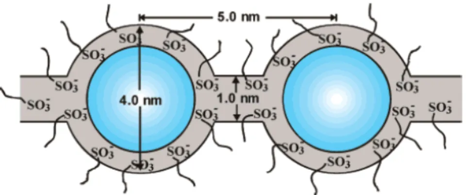
Among the earliest concepts, Yeager and Steck proposed a three phase model38 that
was significantly different from that of Gierke et al. based on their studies of the diffusion of various ions. As compared with the model of Gierke et al., the clusters do not have a strict geometrical definition (spherical inverted micelles connected by cylindrical pores) and their geometrical distribution has a lower degree of order. Most importantly, there are transitional interphases between hydrophobic and hydrophilic regions (Figure 1.3.5), a concept that is becoming increasingly accepted.
Figure 1.3.5: The three phase model 38 ,region A, B and C are the fluorocarbon polymer, the interfacial and the ionic cluster region, regions respectively.
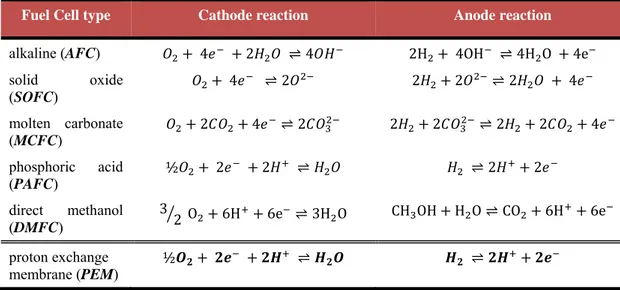
Gebel39 proposed a conceptual description for the swelling and dissolution process
shown schematically in Figure 1.3.6. In dehydrated Nafion, the dry cluster diameter of ~1.5 nm is significantly smaller than the inter-cluster distance of ~2.7 nm, which explains the extremely low ionic conductivity observed at anhydrous state. With the absorption of water, a modification of the cluster structure occurs, which results in the formation of spherical water pools with the ionic groups at the polymer water interface in order to minimize the interfacial energy. The water pool diameter of ~2.0 nm is still lower than the interaggregate distance of ~3.0 nm, which is evidenced by the low ionic conductivity at low water content. When the water volume fraction, is larger than 0.2, the large increase of the ionic conductivity happens, indicating a percolation of the ionic aggregates. The origin of percolation can be probably interpreted as a combination of the effect of the interfacial energy and of the limitation of the swelling due to the polymer chain elastic energy. As the water content increases to between φ~0.3 and 0.5, the structure of spherical ionic domains connected with cylinders of water dispersed in the polymer matrix formed. The ionic domain diameter increases
increasing reveals that both the connectivity and the diameter increase. At φ values larger than 0.5, an inversion of the structure occurs and the membranes correspond to a connected network of rod-like polymer aggregates. Finally, as the membrane “dissolves” into solution, the rod-like structures separate to yield a colloidal dispersion of isolated rods. The structure of highly swollen membranes is then very close to that of the Nafion solution. This model offered a plausible mechanism for the evolution in structure from the widely accepted concept of isolated clusters for membranes containing relatively low water contents to rodlike structures in solution.
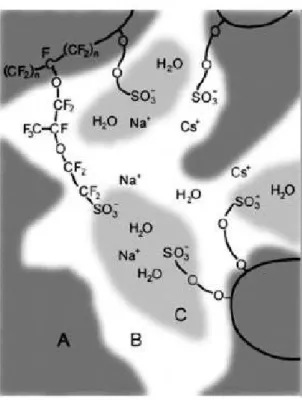
The lamellar model proposed by Litt40 provides a convenient and simple explanation for the swelling behavior of Nafion. Moreover, it is a variation of the
lamellar model proposed by Haubold et al41, in which synchrotron SAXS studies were performed on acid form Nafion 117 samples. The experiments were conducted on dry samples in air and samples equilibrated with water, methanol, and a range of water/methanol mixtures using an in situ flow cell. The scattering cross section data was fitted to a layered model whose basic structure element (i.e., the scattering particle) is a “sandwich”. The outer portion of this sandwich (the “shell”) consists of the side chains, including the sulfonic acid groups, and the inner liquid portion (the “core”) consists of the water/methanol molecules. To provide channels that serve as conduction pathways for protons through the membrane, these structural elements were
proposed to be juxtaposed in a linear fashion so that the liquid core regions are contiguous as is presented in Figure 1.3.7 below.
Figure 1.3.7: Sandwich-like structural element proposed for the morphological organization of Nafion.41
While in 1992 Rubatat42 and co-workers, presented a schematic representation (Figure
1.3.8) of an entangled network of elongated rodlike aggregates in Nafion. Long range heterogeneities arising from bundles of locally ordered aggregates are proposed to give rise to the low angle increase in scattered intensity.
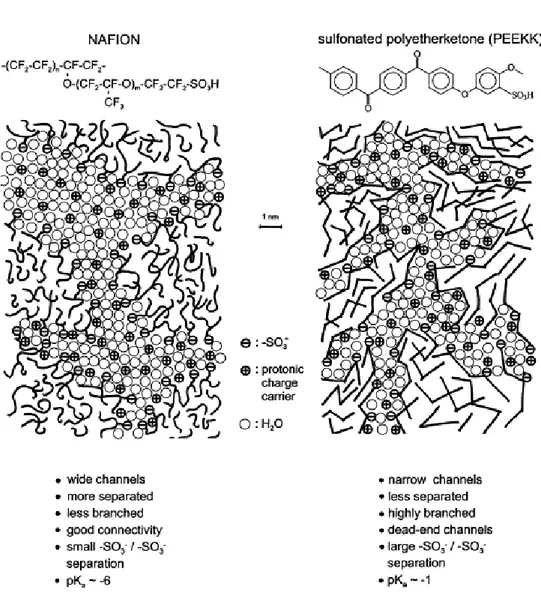
Finally according to Kreuer28 model perfluorosulfonic polymers naturally combine, in one macromolecule, the extremely high hydrophobicity of the perfluorinated backbone with the extremely high hydrophilicity of the sulfonic acid functional groups. Especially in the presence of water, this gives rise to some hydrophobic/hydrophilic nano-separation. The sulfonic acid functional groups aggregate to form a hydrophilic domain. When this is hydrated, protonic charge carriers form within inner space charge layers by dissociation of the acidic functional groups, and proton conductance assisted by water dynamics occurs. While the well connected hydrophilic domain is responsible for the transport of protons and water, the hydrophobic domain provides the polymer with the morphological stability and prevents the polymer from dissolving in water. The situation in sulfonated polyetherketones was found to be distinctly different with respect to both transport properties and morphological stability. As a result of the smaller hydrophilic/hydrophobic difference (the backbone is less hydrophobic and the sulfonic acid functional group is less acidic and therefore, also less polar) and the smaller flexibility of the polymer backbone, the separation into a hydrophilic and a
hydrophobic domain is less pronounced. As schematically illustrated in Figure 1.3.10,
the water filled channels in sulfonated PEEKK are narrower compared to those in Nafion. They are less separated and more branched with more dead-end “pockets”. These features correspond to the larger hydrophilic/ hydrophobic interface and, therefore, also to a larger average separation of neighbouring sulfonic acid functional groups. The stronger confinement of the water in the narrow channels of the aromatic polymers leads to a significantly lower dielectric constant of the water of hydration.
The nature of the crystalline component in Nafion has received much less attention than that of the ionic domains, and thus, the relevance of this morphological feature to the technologically important properties of the membranes is still unclear. Since the initial studies of Nafion morphology, the crystalline component has been recognized as an important structural feature and often considered as a necessary component that provides mechanical integrity and a barrier to solvent swelling. With respect to current models, however, the crystallites may be considered to exist within elongated polymeric aggregates or as critical structures that impose the organization of the ionic domains. In the rodlike models, the crystallites may play a minor role to that of entanglements in affecting the mechanical behavior of the swollen membranes. On
the other hand, the lamellar model suggests that the crystallites are the principal factor
in limiting ionic domain swelling34.
Figure 1.3.10: Schematic representation of the microstructures of Nafion and a sulfonated polyetherketone. 28
1.4 Proton Conduction Mechanisms in PEM
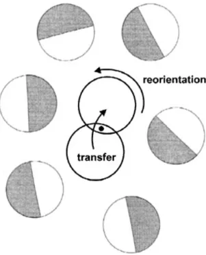
In metals, proton transfer generally occurs between the interstitial octahedral or tetrahedral sites, resulting in long-range proton transport, i.e. diffusion. However, in non-metallic environments, the proton mobility requires not only proton transfer reactions within the hydrogen bonds but also structural reorganization, as illustrated schematically in Figure 1.4.1.
Figure 1.4.1: Schematic diagram of the two reaction steps in long range proton transport. 43
Proton transport mechanism through a PEM is basically conduction through water. The dominant intermolecular interaction in water is hydrogen bonding. The introduction of an extra proton leads to proton defects, resulting in a contraction of hydrogen bond in the vicinity of such defects. The binding power of a water molecule depends on the number of hydrogen bonds involve in it. This also leads to relaxation effects in the neighboring hydrogen bonds as a response to the formation and cleavage of hydrogen bonds. When a hydrogen bond is formed, the surrounding bonds are weakened but the cleavage of hydrogen bonds strengthens the neighboring bonds43-45. Therefore, defects caused by the incorporation of excess protons weaken the
intermolecular interaction by means of breakage and reformation of bonds in combination with large variations in bond length43, 46-48.
Excess protons can be a part of a dimer (H5O2+, ‘Zundel’ ion) or a part of a
hydrated hydronium ion (H9O4+, ‘Eigen’ ion). The central bond of H5O2+ (≈250 pm) is
noticeably contracted compared to the average hydrogen bond length in bulk water (≈280 pm) but elongated compared to an isolated dimer (≈240 pm). Figure 1.4.2 shows the formation of an ‘Eigen’ ion from a Zundel’ ion and the change in protonic charge from one ion to another. In a proton exchange membrane, the hydrated environment, often acidic, acts as a solvent for the diffusion of hydronium and dimer ions formed49.
Figure 1.4.2: Transport mechanism of Protonic defects in water.46
Proton conduction is fundamental for proton exchange membrane fuel cells and is usually the first characteristic considered when evaluating membranes for potential fuel cell use. High conductivity is essential for the required performance especially at high current density. At a molecular level, the proton transport in hydrated polymeric matrices is in general described on the basis of either of the two principal mechanisms: “proton hopping” or “Grotthus mechanism” and “diffusion mechanism” which water is as vehicle or “vehicular mechanism”50-52. In proton hopping mechanism protons hop from one hydrolyzed ionic site (SO3- H3O+) to another across the membrane. The
produced proton by oxidation of hydrogen in anode adheres to water molecule than the provisional hydronium ion is formed and one different proton from same hydronium
ion hops on the other water molecule. In this mechanism, ionic clusters were swelled in presence of water and formed the percolation mechanism for proton transferring. The simple scheme of the hopping mechanism has been shown in Figure 1.4.3. The hopping mechanism has little contribution to conductivity of perflourinated sulfonic acid membranes such as Nafion12.
Figure 1.4.3: Scheme of the hopping mechanism.53
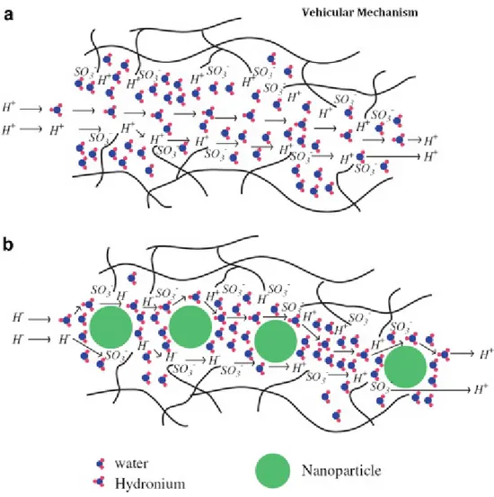
The second mechanism is a vehicular mechanism. In this mechanism hydrated proton (H3O+) diffuses through the aqueous medium in response to the electrochemical
difference. In vehicular mechanism, the water connected protons (H+(H2O)x) in the
result of the electroosmotic drag carry the one or more molecules of water through the membrane and itself are transferred with them. The major function of the formation of the vehicular mechanism is the existence of the free volumes within polymeric chains in proton exchange membrane which allow the transferring of the hydrated protons through the membrane. The schematic design of the vehicular mechanism in proton conduction in pristine and nanocomposite membranes has been shown in the Figure 1.4.4. Water also has two suggested transport mechanisms: electroosmotic drag and concentration gradient driven diffusion (this probably occurs as self associated clusters: (H2O)y). The hydrophobic nature of Teflon backbone facilitates the water transfer
through the membrane because the surfaces of the hydrophobic holes tend to repel the water molecules53.
The prevalence of one or the other mechanism depends on the hydration level of the membrane. On the other hand, the mechanism of proton transport within nanocomposite and hybrid systems based on the aforementioned membranes is a much more complex process as it involves both the surface and chemical properties of the inorganic and organic phases. Although the exact role of inorganic components in
stabilizing the proton transport properties of nanocomposites based on Nafion and other polymers is still under discussion, it may be presumed that the primary function of the nanoparticles is to stabilize the polymer morphology with increasing temperature. If the inorganic additive happens to be an alternative proton transporter like heteropolyacids, their contribution to the transport processes has also to be analyzed. Proton conductivity improvements would, however, depend upon whether the fraction of bulk water and the bulk proton concentrations are increased as a result of the inorganic additives or not12.
Figure 1.4.4: Schematic design of the Vehicular Mechanism as proton conduction in (a) pristine membranes and (b) polymer/ nano-particle composite membranes.12
1.5 High Temperature PEM fuel cells (HT-PEMFCs)
Polymer electrolyte fuel cells based upon PFSA membranes have typically been operated in a temperature range between approximately 50 and 90 °C. This temperature range is a compromise between competing factors. Increasing the operating temperature above room temperature will improve the electrode kinetics of the oxygen reduction reaction. The upper limit of temperature results from the difficulty in maintaining membrane water content at temperatures at or above 100 °C. In addition, temperatures above the polymer glass transition temperature (110 °C for protonated Nafion) can cause polymer chain rearrangements, which can lead to structural changes in the membrane and lower the membrane stability, performance, and lifetime.
In recent years, increasing interest has been devoted to the development of high temperature proton conducting polymer electrolyte fuel cell systems. In fact, most of the key issues and shortcomings of the PFSA-based PEMFC technology, such as water management, CO poisoning, cooling and heat recovery, can be solved or avoided by developing alternative membranes with suitable ionic conductivity and stability up to 120-130 °C.
The US Department of Energy (DOE) has a major effort to develop new membranes which can operate under drier conditions and at temperatures up to 120 °C54. Polymer membranes able to operate above 120 °C could benefit from both enhanced carbon monoxide (CO) tolerance and improved heat removal21. Higher temperature operation includes the following:
(i) The kinetics for both electrode reactions will be enhanced.
(ii) Above the boiling point of water, operation of PEMFCs involves only a single phase of water, i.e., the water vapor, and therefore can be simplified. (iii) The heat can be recovered as, e.g., steam, which in turn can be used either
for direct heating or steam reforming or for pressurized operation. In this way the overall system efficiency will be significantly increased.
(iv) The operational temperature of a fuel cell around 200 °C is close to
temperatures for methanol reforming and for hydrogen desorption of the newly developed high capacity storage materials. This will allow for an
integration of the fuel cell with a methanol reformer or a high-capacity hydrogen storage tank.
(v) The CO tolerance will be dramatically enhanced
The carbon monoxide concentration CO in the H2 feed gas affects the performance of a
membrane at low temperatures. If the concentration of CO is excessive (∼10 ppm), it will strongly adsorb to the platinum (Pt) surface and poison the platinum electro-catalyst 55-58 (Figure 1.5.1).
Figure 1.5.1: Adsorption of CO on Pt .49
Indeed, the adsorption of CO on Pt is associated with high negative entropy, implying that adsorption is favored at low temperatures, and disfavored at high temperatures59. The CO tolerance will be dramatically enhanced, from 10-20 ppm of CO at 80 °C, to 1000 ppm at 130 °C, and up to 30000 ppm at 200 °C21.
However, there are also some technical obstacles during high temperature treatment of polymer electrolyte membranes. Polymer membranes are incapable of operating at high temperatures because water from the membrane evaporates out resulting in a loss of proton conductivity60. High proton conductivity is essential for achieving a high power density in fuel cells. Dehydration of the membrane at high temperatures may lead to decrease the proton conductivity value and in the process performance of polymeric membranes gets hampered. Water is very essential for the proton conductivity because it promotes the dissociation of protons from the sulfonic acid groups, and provides highly mobile hydrated protons. Hence, hydration is the key factor for maintaining the optimal performance of the membranes. The conductivity of a dry membrane is several orders of magnitude lower than a fully saturated membrane. To keep the membrane hydrated, one or both reactant gas streams must be humidified49. However, too much
humidification causes flooding of the electrodes and consequently, the diffusion overpotential increases due to insufficient oxygen and hydrogen supply. In order to reduce these overpotentials, properties such as stable water uptake and high proton conductivity are essential for the electrolyte.
A number of alternative strategies 61-64 have been proposed to satisfy these requirements and to maintain membrane conductivity in a dehydrating environment (i.e. elevated temperature and reduced relative humidity), such as composite membranes containing finely dispersed fillers in the ionomer matrix. The following section is dealing with these composite membranes, the influence of these particles on membrane properties, such as conductivity and permeability to methanol, is also discussed.
1.5.1 Composite Membranes
As is mentioned in the previous paragraph, the main obstacles to greater commercialization of polymer electrolyte fuel cells are mostly related to the low-proton conductivity at low relative humidity, to the high methanol cross over, and their poor mechanical properties above 100 °C.5 Therefore, several approaches have been adopted
to modify the polymeric membrane in order to maintain the proton conductivity as well as the performance of the membrane at high temperatures, and can be used in fuel cell applications. An approach is the development of composite membranes, where particles of organic/inorganic fillers homogeneously dispersed in the ionomer matrix. Modified Nafion membranes containing hygroscopic inorganic fillers such as, titania nanotubes 65 and particles66, 67, SiO2 68-71, ZrO2 72, Fe2O3 73, and other compounds characterized by
water retention capacity or by proton conduction as hetero-poly-acids (PWA, PMoA, SiWA) or layered zirconium phosphate5, 74-77 are valid materials to use as polymer electrolytes in PEMFC. For Nafion ionomer bearing – SO3H groups, the filling with
ZrP, silica, or heteropolyacid nano-particles has a positive effect on fuel cell performance at temperatures higher than 90 – 100 °C, even for relative humidity considerably lower than 100%. This effect can be connected to the notion that these hydrophilic particles replace the loosely bonded water within the hydrophilic Nafion domains5. As hydrophilic additives, the presence of these inorganic compounds
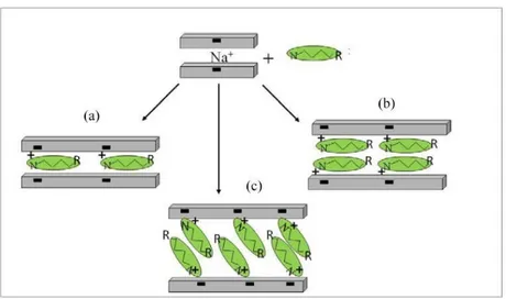
decreases the chemical potential of the water inside the membrane and therefore creates an additional pathway for the proton conduction. At the same time, they provide hydrogen-bonding sites for water in the membrane so that the hydration of the membrane will be increased and the transport and evaporation of water will be reduced1. The water interacting with the surface of the filler is more likely to be retained than loosely bonded water in unmodified Nafion, but still mobile enough to allow fast proton transport. Additionally, the inclusion of inorganic fillers improves the mechanical properties and the membrane water management. The mechanical reinforcement of the membrane, and hence the reduction of the swelling properties play an important role, especially in the temperature range 90 - 110°C, where high humidification conditions can be still obtained at acceptable pressures of the cell. Moreover the properties of these composite membranes not only depend on the ionomer and the solid used but also on the amount, homogeneous dispersion, size, and orientation of the solid particles dispersed in the polymeric matrix. Layered compound can be inserted (i) as powered performed particles, (ii) as performed exfoliated lamellae, (iii) by in situ formation of in the ionomer solutions and (iv) by in situ precipitation in performed membranes of the pure ionomer. Based on the above composite membranes can be prepared according to two main procedures: (i) dispersion of filler particles in an ionomer solution followed by casting, and (ii) growth of the filler particles within a performed membrane or in an ionomer solution. In the first procedure the solids are first ground until a fine powder is obtained and then dispersed under strong stirring in an organic solution of the polymer. Finally the membrane is obtained by film casting and solvent elimination5. Because the composite membrane is obtained by casting an ionomer solution in organic solvents, colloidal dispersions of exfoliated layered materials must be formed in the ionomer solvent or in similar solvents. Depending on the degree of crystallinity of the starting material and on the conditions used in the deintercalation process, it is possible to obtain dispersions of lamellar particles with thickness ranging from ~10 to 100 nm and surface area from ~0.1 to 10 μm2.
Furthermore, for each type of the above composite membranes, the properties not only depend on the ionomer and the solid used but also on the particle content, particle size, homogeneous distribution and orientation of the exfoliated particles, and exfoliation degree. If the use of composite membranes is confined to direct methanol fuel cells it is
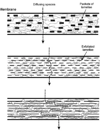
imperative to overcome the large methanol cross-over of pure ionomer membrane. In Figure 1.5.2 is schematically shown the effect of all the above properties to the performance of the nanocomposite membrane, in this images is shown the increase of the tortuous path encountered by a given diffusing species with increasing degree of exfoliation and/or lamellar particles5.
Figure 1.5.2: Schematic view of a hybrid ionomeric membrane containing orientied lamellae of ZrP. 5
In this present Doctoral thesis, two dimensional (2D) materials, phyllomorphous materials, such as, Clays, Graphite Oxide and Layered Double Hydroxides (LDHs), were studied as candidates fillers for the polymer electrolyte membranes in PEMFC. Composite membranes, were prepared according the first procedure, dispersing the filler particles in Nafion ionomer solution followed by casting. The study focused on the creation of novel nanocomposite membranes with high proton conductivity and enhanced water retention properties, even at high temperatures.