Measurement and Optimization of LTE
Performance
Stefania Zinno
Supervisor: Prof. Giorgio Ventre
Department of Electrical Engineering and Information Technology
Università degli Studi di Napoli Federico II
This dissertation is submitted for the degree of
Doctor of Philosophy
Acknowledgements
First and foremost I want to thank my advisor Professor Giorgio Ventre for the continuous support of my studies and related research, for his patience, motivation, and immense knowledge.
This PhD thesis is the result of a long path journey, planned and thrived together. We started back with my bachelor thesis in “Definizione della Qualità del servizio in Reti Wireless Beyond 3G" and then kept on going with "Un Algoritmo di Load Balancing Per Reti LTE contro gli Attacchi Denial of Service" to finally reach this milestone. He is THE guide and THE light in my professional carrier and has always forecasted my professional growth. He gave me the opportunity to learn and to learn how to teach others keeping always in mind that curiosity is the key that leads to a good work. I’ve spent the last years being a student between fellow students from all around the world. This experience has given me the opportunity to teach but most of all to learn from each and every of them. To this day I could not be more grateful for an opportunity that still blows my mind every day. I am also thankful for the excellent example he has provided as a successful Head of the Department and Professor.
Besides my advisor, I would like to thank Prof. Stefano Avallone and Prof. Nicola Pasquino for their insightful comments and encouragement, but also for the hard demand that kept me incented to widen my research from various perspectives. I really appreciate Stefano’s caring patient and faithful support during all and the final stages of this Ph.D. I would also like to express my special appreciation and thanks to Nicola. I very much appreciated his enthusiasm, intensity, willingness to do frequent experiments and amazing ability to cleave and challenge me.
Another amazing thank you goes to Giovanni who has been there from ground zero and still has my back.
I thank my fellow ARCLAB and all my PhD mates in for the stimulating discussions, for the lunch breaks and for all the fun we have had in the last four years.
And eventually I am forever indebted to my Academy Colleagues for their enthusiasm, guidance, and unrelenting support throughout this process. They have routinely gone beyond
vi
their duties to soothe my worries, concerns, and anxieties, and have worked to instil great confidence in both myself and my work.
Abstract
4G Long Term Evolution (LTE) mobile system is the fourth generation communication system adopted worldwide to provide high-speed data connections and high-quality voice calls. Given the recent deployment by mobile service providers, unlike GSM and UMTS, LTE can be still considered to be in its early stages and therefore many topics still raise great interest among the international scientific research community: network performance assessment, network optimization, selective scheduling, interference management and coexistence with other communication systems in the unlicensed band, methods to evaluate human exposure to electromagnetic radiation are, as a matter of fact, still open issues.
In this work techniques adopted to increase LTE radio performances are investigated. One of the most wide-spread solutions proposed by the standard is to implement MIMO techniques and within a few years, to overcome the scarcity of spectrum, LTE network operators will offload data traffic by accessing the unlicensed 5 GHz frequency. Our Research deals with an evaluation of 3GPP standard in a real test best scenario to evaluate network behavior and performance.
Table of contents
List of figures xiii
List of tables xv
List of Symbols xvii
Introduction xxi
1 LTE Architecture and Radio Procedures 1
1.1 Overview of LTE Architecture . . . 1
1.1.1 The User Equipment UE . . . 1
1.1.2 Evolved UMTS Terrestrial Radio Access Network E-UTRAN . . . 2
1.1.3 Evolved Packet Core EPC . . . 2
1.2 LTE Radio Procedures . . . 3
1.2.1 LTE Radio Resource . . . 5
1.2.2 LTE Carrier Aggregation . . . 8
1.2.3 Adaptive Modulation and Coding (AMC) . . . 10
1.3 Feedback mechanism in LTE . . . 12
1.3.1 Reference Signal Received Power (RSRP) . . . 13
1.3.2 Received Signal Strength Indicator (RSSI) . . . 13
1.3.3 Reference Signal Received Quality (RSRQ) . . . 13
1.3.4 Signal to Interference plus Noise Ratio (SINR) . . . 14
1.4 Throughput Estimation . . . 14
2 LTE MIMO Techniques 19 2.1 Improving Efficiency and Throughput with MIMO . . . 19
2.1.1 MIMO in LTE . . . 19
2.1.2 Mode Support in LTE . . . 23
x Table of contents
2.3 Open, Closed Loop - Spatial Multiplexing . . . 25
2.3.1 Open Loop . . . 26
2.3.2 Closed Loop . . . 26
2.3.3 Transmit Diversity and Closed-Loop Rank-1 - Spatial Multiplexing 26 2.4 MU-MIMO . . . 27
2.5 MIMO Reporting . . . 27
3 LTE in Unlicensed Bandwidth 31 3.1 Brief Overview of LTE and Wi-Fi Access Techniques . . . 31
3.1.1 Wi-Fi . . . 31
3.2 Problem Statement . . . 35
3.3 Basic techniques for a fair coexistence of Wi-Fi and LTE . . . 36
3.3.1 Listen-Before-Talk . . . 36
3.3.2 Almost Blank Subframe . . . 37
3.3.3 Minor techniques . . . 39
3.4 Standardization Efforts . . . 40
3.4.1 LTE-U . . . 40
3.4.2 Licensed Assisted Access . . . 42
3.4.3 MuLTEfire . . . 44
3.5 LTE First Steps in the Unlicensed Spectrum . . . 45
3.6 Performance analysis of Wi-Fi in presence of LTE cells . . . 47
3.7 Research proposals for a fair coexistence of LTE and Wi-Fi . . . 51
3.7.1 Approaches based on Listen-Before-Talk . . . 51
3.7.2 Almost Blank Subframe . . . 64
3.7.3 Minor techniques . . . 66
4 A Smartphone-Based Assessment of LTE Measurement Procedures 69 4.1 Aim of the Research . . . 69
4.2 Smartphone-based Assessment and Methodology Overview . . . 69
4.3 Experimental Setup . . . 72
4.3.1 Smartphone-Based Measurement Methodology . . . 72
4.3.2 Test Methodology . . . 75
4.3.3 Aim of the Research . . . 76
4.4 Experimental Results and Discussion . . . 77
4.4.1 SINR . . . 77
4.4.2 CQI, SINR and RSRP Analysis . . . 79
Table of contents xi
4.4.4 Modulation and Throughput . . . 84
4.4.5 Downlink throughput . . . 86
4.4.6 Comparing SINR and Throughput . . . 89
4.5 Conclusions . . . 90
5 LTE MIMO: Experimetal Assessment 93 5.1 Aim of the Research . . . 93
5.2 MIMO Overview in LTE . . . 93
5.3 Experimental Setup . . . 96
5.3.1 NEMO Handy Assessment . . . 96
5.4 Preliminary Results . . . 99
5.4.1 Reference Signal Received Power (RSRP) . . . 99
5.4.2 Reference Signal Strength Indicator (RSSI) . . . 101
5.4.3 Reference Signal Received Quantity (RSRQ) . . . 103
5.4.4 Signal to Interference Noise Ratio (SINR) . . . 103
5.5 MIMO Analysis . . . 106
5.5.1 Physical Layer Quantities Statistical Analysis . . . 108
5.5.2 Channel State Information (CSI) Reporting Analysis . . . 111
5.6 Conclusions . . . 113
6 Conclusions 115
List of figures
1.1 3GPP LTE Architecture . . . 2
1.2 eNodeB Functional Structure . . . 4
1.3 Donwlink OFDM Frame - TS 36 213 . . . 6
1.4 Mapping of downlink reference signals Normal CP - TS 36 211 . . . 7
1.5 3GPP Carrier Aggregation (FDD) . . . 9
1.6 3GPP Inter and Intra Band Carrier Aggregation . . . 9
1.7 Scheduling Architecture . . . 12
2.1 MIMO Implementation . . . 21
2.2 SU-MIMO . . . 24
2.3 MU-MIMO . . . 28
2.4 Rank Reporting for mapping MIMO layers . . . 30
3.1 Distributed Control Function - RTS/CTS . . . 34
3.2 Almost Blank Subframe Structure . . . 38
3.3 LTE Duty Cycle . . . 39
3.4 Channel Assessment Procedure . . . 41
3.5 Listen Before Talk based on LBE - TR 36.889 . . . 43
4.1 eNodeBs Crowd Sensing . . . 73
4.2 eNodeB’s Map along the Route and Handover Occurrence . . . 73
4.3 SINR Evolution . . . 78
4.4 SINR empirical distribution. . . 78
4.5 CQI vs. SINR . . . 80
4.6 Regression of SINR as a function of CQI . . . 82
4.7 CQI CDF per Modulation . . . 83
4.8 SINR vs Throughput . . . 85
4.9 Downlink throughput . . . 86
xiv List of figures
4.11 Throughput empirical CDF. . . 88
4.12 SINR vs. Throughput for PCC. . . 90
4.13 Handover Map . . . 91
5.1 Typical test drive configuration . . . 95
5.2 MIMO Configuration . . . 97
5.3 Reference Signal Received Power - RSRP . . . 100
5.4 Reference Signal Strength Indicator - RSSI . . . 102
5.5 Reference Signal Received Quality - RSRQ . . . 104
5.6 RS Signal Reported - SINR . . . 105
5.7 TM Implementation with respect of frequencies . . . 106
5.8 RS-related quantities density for each Transmission Mode and CodeWord for Freq. 800 MHz . . . 107
5.9 RS-related quantities density for each Transmission Mode and CodeWord for Freq. 2100 MHz . . . 107
5.10 RS related quantities for Freq. 800 MHz . . . 109
5.11 RS related quantities for Freq. 2100 MHz . . . 109
5.12 CQI Reporting for each Transmission Mode and CodeWord for Freq. 800 MHz110 5.13 CQI Reporting for each Transmission Mode and CodeWord for Freq. 2100 MHz110 5.14 Rank Reporting for each Transmission Mode . . . 112
List of tables
1.1 CQI per Coding Rate and Modulation . . . 15
1.2 UE Category and Maximum number of TB bits . . . 16
1.3 Modulation and TBS Index Table . . . 17
2.1 Different Antenna Schemes and Benefits . . . 20
2.2 Transmission Mode Table 7.2.3-0 - TS 36213 . . . 22
2.3 TM 1,2,3,4 vs CSI . . . 28
3.1 Wi-Fi Physical Layers . . . 33
3.2 Mean e.i.r.p. limit in dBm - ETSI EN 301 893 . . . 39
3.3 Taxonomy of research works . . . 53
4.1 Measurement device and software versions . . . 74
4.2 Peak Throughput . . . 76
4.3 SINR Statistics . . . 79
4.4 CQI as a function of RSRP and SINR . . . 81
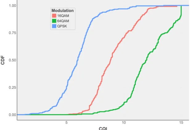
4.5 CQI Statistics per Modulation . . . 84
4.6 Throughput Statistics per Modulation . . . 85
4.7 Downlink throughput statistics . . . 88
4.8 SINR statistics per throughput classes . . . 89
5.1 Measurement Tools . . . 96
5.2 Nemo Handy Documentation CELLMEAS . . . 97
5.3 Nemo Handy Documentation CQI . . . 98
5.4 Nemo Handy Documentation CI . . . 98
5.5 Nemo Handy Documentation CHI . . . 98
5.6 RSRP Mapping - TS 36133 . . . 99
5.7 RSSI Mapping - TS 25133 . . . 101
xvi List of tables
List of Symbols
SISO Single Transmission Antenna and Single Receiver Antenna SU-MIMO Single User MIMO
MU-MIMO Multi User MIMO RS Reference Signal
RRM Radio Resource Management QoS Quality of Service
TB Transport Block CP Cyclic Prefix
AMC Adaptive Modulation and Coding ARO Application Resource Optimizer BLER Block Error Rate
CA Carrier Aggregation CQI Channel Quality Indicator CSI Channel State Information FDD Frequency Division Duplexing FIA Fast and Independent Adjustment KPI Key Performance Indicator LTE Long Term Evolution
xviii List of Symbols
MCS Modulation Coding Scheme MIMO Multiple Input Multiple Output
OFDM Orthogonal Frequency Division Multiplexing OFDMA Orthogonal Frequency Division Multiple Access PCC Primary Component Carrier
RB Resource Blocks
RE Resource Elements
SCA Slow and Centralized Adjustment SCC Secondary Component Carrier
SINR Signal-to-interference-and noise Ratio TDD Time Division Duplexing
TTI Transmission Time Interval
UE User Equipment
PRB Physical Resource Block RI Rank Indicator
PMI Pre-coding Matrix Indicator CP Cyclic Prefix
RSRP Reference Signal Received Power RSRQ Reference Signal Received Quality RSSI Reference Signal Strength Indicator 3GPP 3rd Generation Partnership Project
HO Handover
TBS Transport Block Size
xix
FSTD frequency switched transmit diversity SNR Signal to Noise Ratio
E-UTRAN Evolved UMTS Terrestrial Radio Access Network EPC Evolved Packet Core
SAE System Architecture Evolution EPS Evolved Packet System
ME Mobile Equipment
P-GW The Packet Data Network Gateway PDN The Packet Data Network
APN Access Point Name GGSN GPRS Support Node
SGSN Serving GPRS Support Node HSS Home Subscriber Server S-GW Serving Gateway
MME Mobility Management Entity
PCRF Policy Control and Charging Rules Function UICC Universal Integrated Circuit Card
USIM Universal Subscriber Identity Module MT Mobile Termination
TE Terminal Equipment
LTE-LAA Licensed Assisted Access-Long Term Evolution epdf experimental probability density function
TM Transmission Mode
xx List of Symbols
FDPS Frequency domain packet scheduling
SM-MIMO Spatial multiplexing Multiple Input Multiple Output MLD-IS maximum-likelihood detection interference suppression ICI Inter Carrier Interference
Introduction
The aim of this work is to investigate on the LTE network operating in both licensed and unlicensed spectrum, in order to propose ways to improve performance and efficiency.
LTE MAC layer uses Carrier Aggregation (CA) mechanism exploiting both licensed and unlicensed spectrum to achieve higher performances, throughput and efficiency. LTE mobile system also adopts Adaptive Modulation and Coding (AMC) [1] as a link adaption mechanism and can schedule frequencies both in the licensed and unlicensed bandwidths. In fact, MAC is based on the User Equipment (UE) periodically reporting channel condition summarized through Channel Quality Indicator (CQI) which, in turn, is based on Signal-to-Interference-plus-Noise Ratio (SINR) and Reference Signal Received Power (RSRP).
Since Release 8, 3rd Generation Partnership Project (3GPP) adopted MIMO techniques in LTE standard [2]. The use of MIMO allows the network to improve performance due to the main features of the Multiple Input Multiple Output transmission modes. With MIMO, rather than considering multi-path propagation signals, present in all terrestrial communications, as thermal noise, LTE physical transmissions can consider as a constructive redundancy signals propagating along different paths.
Adopting MIMO involves having multiple antennas at both the transmitter and receiver sides. Also the antennas are able to distinguish different paths between the entities, processing power levels available at both end-point of the link, providing improvements in data rate of signal to noise. To investigate these topics, this thesis deals with the efficient evaluation of the relationship between SINR, RSRP and CQI and also with how to assess AMC effects on LTE performance and with the basic procedures related to MIMO implementation and adoption.
As suggested by the present state of the art, to fully investigate how these techniques work, experimental campaign were conducted through software simulations or measurement campaigns performed in controlled environment such as anechoic chambers. Simulations are commonly adopted because it is very hard to access operators statistics and data, and changes in the network configuration are easy to evaluate and to arrange using a software, while in a real test-bed scenario involving a real operator, even minor variations in the
xxii Introduction
network configuration can affect end-users QoS perception. In our vision campaigns [3–6] lack precious information, not accounting properly actual channel condition and physical phenomena that a user commonly experiences in his/her everyday usage of the network. To fully address real issues and to fully assess network performance it was fundamental to have a real-time interaction with a real network operator. Although in its early stages of development, the methodology here adopted benefit from smartphones as measurement devices. Due to its novelty it arises as the most appropriate and led us the opportunity to test network performance during actual usage and in a common user scenario.
To overcome the lack of spectrum resources and to further improve LTE capacity, the pro-posal of extending the standard to the readily available unlicensed spectrum is receiving much attention. However, gaining capacity in a band where Wi-Fi is widely used and guaranteeing a fair coexistence between systems is not an easy-to-address issue. Analyzing the impact of operating LTE in the unlicensed band on the performance of Wi-Fi and devising solutions to minimize such an impact have been the goals of a considerable amount of work carried out by the research community, standardization bodies and telecom operators. A solution to overcome the scarcity of spectrum is to extend LTE by introducing the capability to directly exploit the unlicensed spectrum [7]. The targeted band is the 5 GHz U-NII (Unlicensed National Information Infrastructure) band, because of the availability of approximately 600 MHz already released for usage. However, this band is already being used by Wi-Fi net-works (IEEE 802.11a/n/ac/ax), weather radar transmissions, medical devices and some other wireless systems. Therefore, it is necessary for LTE to fairly coexist with such technologies in the targeted unlicensed spectrum. A study on the state of the art and current measurement methodologies, advocating the fair coexistence of LTE and other systems in the unlicensed spectrum, exploring standards and coexistence mechanism, is provided in chapter three.
Chapter 1
LTE Architecture and Radio Procedures
1.1
Overview of LTE Architecture
The System Architecture Evolution (SAE) offers a number of key advantages over previous technologies and systems used for cellular networks spanning from higher spectral efficiency, higher peak data rates, shorter round trip time, increase in variety of frequencies to use and wider bandwidths. Nowadays in fact, the focus of mobile broadband systems is to be able to handle much greater numbers of data transmissions and to ensure levels of latency that have been reduced to around 10 ms.
The Long Term Evolution (LTE) Evolved Packet System (EPS) architecture is comprised of following three main components:
- User Equipment (UE)
- Evolved UMTS Terrestrial Radio Access Network (E-UTRAN) - Evolved Packet Core (EPC).
The evolved packet core represents the link between packet data networks (Internet), private enterprise networks or an IP multimedia system.
1.1.1
The User Equipment UE
As for UMTS and GSM, the architecture of the user equipment for LTE is called Mobile Equipment (ME). The mobile equipment is composed by the following:
- Mobile Termination (MT) taking care of all the communication functions, - Terminal Equipment (TE) terminating the informations streams,
2 LTE Architecture and Radio Procedures
Fig. 1.1 3GPP LTE Architecture
- Universal Integrated Circuit Card (UICC) known as the SIM card for LTE equipments. It comes with the well-known application called USIM.
1.1.2
Evolved UMTS Terrestrial Radio Access Network E-UTRAN
UTRAN was first introduced in 3GPP Release 8 as the access part of LTE Architecture. E-UTRAN handles the radio communications between the mobile and the EPC and is composed by evolved base stations, called eNodeBs or eNBs. The eNB controls also low-level operation sending signalling messages such as handover commands. Each eNB controls the UEs in one or multiple cells but LTE mobiles communicate with just one base station and one cell at a time. Each eNB then, connects with the EPC by means of the S1 interface and it can also be connected to nearby base stations by the X2 interface as shown in Fig. 1.1.
1.1.3
Evolved Packet Core EPC
While with GSM, the architecture relies on circuit-switching, LTE was designed to adopt IP as the key protocol to handle all services. EPC in SAE handles the overall control of the UE.
Here is a brief description of each of the components shown in Fig. 1.1:
- The Packet Data Network Gateway (P-GW) represents the conjunction with a The Packet Data Network (PDN), through SGi interface. Each PDN is labelled by an Access Point Name (APN). A PDN gateway acts as the GPRS Support Node (GGSN) and the Serving GPRS Support Node (SGSN) used in UMTS and GSM networks.
1.2 LTE Radio Procedures 3
- Serving Gateway (S-GW) behave as a router and forwards informations between an eNodeB and the PDN gateway.
- Home Subscriber Server (HSS) is a centralized database that contains information about all the network operator’s subscribers.
- Mobility Management Entity (MME) in charge of all the higher-level operation of the UE interpreting signalling messages and HSS. It is also responsible for tracking area list management, selection of PGW/SGW and also selection of other MME during handovers. MME takes care of bearer management functions including establishment of dedicated bearers for all signaling traffic flow.
- Policy Control and Charging Rules Function (PCRF) is the main responsible for what concerns policy control and decision-making. The serving and PDN gateways are connected through the S5/S8 interface.
1.2
LTE Radio Procedures
To improve LTE performances and to share the channel among multiple users, 3GPP introduced Orthogonal Frequency Division Multiple Access (OFDMA). OFDMA uses Orthogonal Frequency Division Multiplexing (OFDM) for downlink physical transmission. All the resources that can be allocated to a user are scheduled by eNodeBs equipped with fully structured packet schedulers.
To even further improve LTE performances the architecture combines a large number of separate LTE carriers to provide a wider spectrum to users, in fact Carrier Aggregation (CA) mechanism was introduced by 3GPP since Release 10. CA allows the user to have a Primary Component Carrier (PCC) as an anchor to the eNodeB and one or multiple Secondary Component Carrier (SCC) as offloading carries. OFDM as a digital multi-carrier modulation method together with CA tries to take network performance at a whole new level [8].
Eventually 3GPP addressed the need to improve transmission reliability and rate, so it adopted Adaptive Modulation and Coding (AMC) to adapt the Modulation Coding Scheme (MCS) used by the user. A UE periodically reports to the eNodeB the measured channel quality trough the Channel Quality Indicator (CQI) to properly set MCS.
OFDMA also facilitates frequency-domain scheduling and is strongly suited to advanced Multiple Input Multiple Output (MIMO) techniques. With MIMO data stream is multiplexed over a large number of narrow-band and orthogonal sub-carriers. The large number of parallel, narrow-band transmission on orthogonal sub-carriers in the frequency domain reduces the
4 LTE Architecture and Radio Procedures
1.2 LTE Radio Procedures 5
impact of interference and increase performance. The following section are going to describe into more detail some of the basic functionalities of an eNodeB (Fig. 1.2).
1.2.1
LTE Radio Resource
OFDM in LTE has two different frame structure: Type 1, which is used for the LTE Frequency Division Duplexing (FDD) mode systems and Type 2 used for the LTE Time Division Duplexing (TDD) systems [9]. Also recently 3GPP Release 13 provided a frame structure of Type 3to allow a fair coexistence in unlicensed bandwidths with Wi-Fi systems [9]. Type 1 frame and type 2 frame have an overall length of 10 ms, with a total of 10 subframes in a frame. Every single subframe is composed by 2 time slots.
The standard also defines together with the frame, composed of 10 adjacent sub-frames, the half-frame, half of the former, which are both used basically to allow for the synchroniza-tion between UEs and eNodeBs and to carry all the necessary control informasynchroniza-tion.
The basic unit of resource is the Resource Blocks (RB). Each RB lasts 1 time slot and occupies 180 kHz spanning on a set of sub-carriers. A RB is the smallest entity that can be scheduled to a UE. Different sets of RBs can then be allocated to different users to support the sharing of the channel resources. Such a division in time and frequency domains allows to efficiently allocate several users on the same channel with fine granularity. The number of available RB depends also on the channel bandwidth that in LTE can have different widths up to 20 MHz. A RB is composed by 12 consecutive subcarriers in the domain of frequency and 6 or 7 symbols in the domain of time. The number of symbols in a frame depends on the Cyclic Prefix (CP) in use. A CP, as the name suggests, is an information that is periodically repeated working as a guard band between LTE symbols. When a normal CP is implemented, every RB has 7 symbols. When an extended CP is used, the Resource Elements (RE) contains 6 symbols. With Type 2 the radio frame is composed of two half frames, each of 5ms duration with a total frame duration again of about 10ms. Every radio frame has a total of 10 subframes and for each subframe 2 time slots are occupied. Also in the standard a RE is defined as the smallest unit which consists of one OFDM sub-carrier during one OFDM symbol interval.
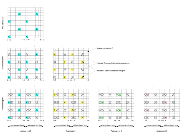
Mostly all LTE channels reserve space for carrying special informations, as a sequence of bits. Reference Signal (RS) is in fact, a special signal that exists at physical layer and higher layer channel rely on its transmission. This is not for carrying any specific information but has the purpose of deliver the reference point for the downlink power. Basically in addition to data, each sub-frame carries also signaling and control information in addition to users’ traffic. Reference symbols are composed by complex values which are determined accordingly to the symbol position as well as of the cell. RS are computed by a two-dimensional orthogonal
6 LTE Architecture and Radio Procedures
Fig. 1.3 Donwlink OFDM Frame - TS 36 213
and a two-dimensional pseudo-random sequence. Downlink data and control informations are multiplexed in time within the same subframe. In each subframe the first 1-3 OFDM symbols are mainly devoted to signaling purpose while the remaining carry out users’ data. This pattern design though is quite flexible from a eNodeB point of view is also able to avoid unnecessary overhead. Data transmission is allowed to occupy the remaining 14 symbols, depending on the containing frame format. LTE cells are always occupying the channel since signaling and control data is continuously sent, even when there is no user data to transmit. Such persistent signal is able to prevent other technologies deployed on the same frequency from transmitting. For instance, Wi-Fi users refrain from transmitting when detecting a signal power above a fixed threshold. RS signals are carried by particular RE in every time slot and the location of the resource elements are specifically determined by the eNodeB transmission configuration. Also when MIMO techniques and different antenna schemes are adopted, knowing that LTE standard defines antenna ports as virtual entities distinguished by their own RS it is pretty straightforward that multiple antenna ports signals can be transmitted on a single transmit antenna and on the contrary a single antenna port can be spread on multiple transmit antennas. In case of two transmit antennas, RSs are inserted from each antenna where the reference signals on the second antenna are offset in the frequency domain by three subcarriers.
The eNodeB scheduler based on configurable parameters measurement adopt different channel characteristics for users’ transmissions. Since OFDMA ideally provides no inter-channel interference, schedulers work with a granularity of one Transmission Time Interval (TTI) and one RB in the time and frequency domain, respectively. At the eNodeB, a first scheduling algorithm is performed in the time domain, and here users are selected for
1.2 LTE Radio Procedures 7
Fig. 1.4 Mapping of downlink reference signals Normal CP - TS 36 211
potential scheduling based on their required QoS. If some user then have pending data for transmission they are re-configured for scheduling in the next TTI. Then the second algorithm in the frequency domain allocates RBs to them.
There are, indeed, several possible methods for scheduling RBs to users, and the LTE standard does not prescribe any particular algorithm to follow. 3GPP LTE Releases left vendors free to adopted their own scheduling algorithm and therefore different networks can employ different scheduling policies, depending on the manufacturer of the devices and the configuration made by the operators. The main goal of an efficient scheduling algorithm has two main purposes, maximize throughput and achieve fairness between users. Today in use there are many algorithms developed for wireless system, such as maximum rate scheduling, Round Robin, best CQI, Proportional Fair, max-min and Resource Fair. Data from the upper layer given to the physical layer in LTE system is basically referred as multiple of Transport Block (TB)s. TBs scheduling process are deployed in the eNodeB which is the one implementing the feedback mechanism to improve channel transmissions based on periodical reports CQIs. Every TTI, all the assessment AMC procedure are performed by the UE, they result into the CQI Report containing all the channel quality information see Fig. 1.7
Based on AMC the eNodeB at first picks the modulation scheme that could be used and then checks for the available physical resources in the RB grid as well as the transmission
8 LTE Architecture and Radio Procedures
parameters including the type of MCS. The FD algorithm uses the channel conditions matrix available from the Channel State Information manager to avoiding experiencing deep fading.
1.2.2
LTE Carrier Aggregation
In order to achieve a higher channel capacity and thus throughput, carrier aggregation was introduced by 3GPP since Release 10. CA allows mobile network operators to combine a number of separate LTE carriers in frequency to provide a wider spectrum to its end-users. CA technology aggregates multiple small band segments into maximum 100 MHz virtual bandwidth to achieve a higher data rate. Extra channels, called Component Carriers, can have different widths and can be allocated and de-allocated on needs. Each station is always connected, though, to a licensed carrier, which is called PCC. While being connected to such PCC, the station can connect to other unlicensed carriers which are called SCC. To each UE several SCC are accessible at the same time. Accordingly to the UE QoS demand and cell capacity, configuration information can be sent via PCC to dynamically remove or add more or less SCCs. All of the SCCs, as mentioned above, can be changed dynamically during the time the user is served by the eNodeB, by means of configuration messages over the PCC. There are two operation modes for LAA: supplemental downlink (SDL) and TDD. SDL mode is the easiest form where the unlicensed bandwidth is mainly used for downlink transmission, as downlink traffic is typically oriented towards user’s information traffic offloading. When using a TDD mode, the unlicensed bandwidth is adopted for both downlink and uplink, as the LTE TDD system practically works in licensed bands. TDD mode grants the flexibility to dynamically exchange resource allocation between downlink and uplink. Although on the user side implementation complexity increases with the implementation of mechanisms such as LBT features and radar detection requirements.
LTE channels can vary in widths, spacing up to 20 MHz in frequency in order to further improve width limits and therefore increase throughput. This technique allows the use of extra frequqncy space, both in the licensed and, hopefully, in the unlicensed spectrum, together with the main channel, to obtain higher capacity. Such extra frequency channels, called component carriers, as shown in Fig. 1.5, can have different bandwidths, i.e. 1.4, 3, 5, 10, 15 or 20 MHz, and can be allocated and de-allocated dynamically. Up to five CC can be simultaneously aggregated to the princiapl carrier allocated to the UE.
All the configured Component carriers are usually not contiguous in the frequency domain. A dynamic allocation of the component carriers allows, for example, telecommunication operators with a higher granularity in fragmenting the spectrum that can provide users a higher data rate by exploiting the overall bandwidth in both unlicensed and licensed spectrum.
1.2 LTE Radio Procedures 9
Fig. 1.5 3GPP Carrier Aggregation (FDD)
Band 1
Band 1
Band 1 Band 2
Intra-band, Contiguous
Intra-band, Non Contiguous
Inter-band, Non Contiguous UE
10 LTE Architecture and Radio Procedures
With respect to the frequency location of the different component carriers, three different cases are possible (Fig. 1.6):
- Intra-band aggregation with frequency-contiguous component carriers; - Intra-band aggregation with non-contiguous component carriers; - Inter-band aggregation with non-contiguous component carriers.
Eventually 3GPP proposed a new concept for LTE radio access network to operate in the unlicensed spectrum as part of a Release 13. It is possible for user to adaptively change from using LTE or Wi-Fi. Obviously a coordination between different Radio Access Technologies is needed and also modification to protocols stacks and interface functionalities need to be improved. Resource allocation becomes an issue to resolve as also user service continuity. In order to meet these requisites, Licensed Assisted Access-Long Term Evolution Licensed Assisted Access-Long Term Evolution (LTE-LAA) is emerging as the candidate technology to be utilized in unlicensed spectrum for wireless data traffic offloading. LAA-LTE uses carrier aggregation combining licensed and unlicensed bands, delivering cellular services to mobile users in the 5-GHz unlicensed band. The deployment of most interest is small cell, which provides access to both licensed and unlicensed spectrum for indoor and outdoor environment.
1.2.3
Adaptive Modulation and Coding (AMC)
Radio Resource Management (RRM) is performed by eNodeBs with the goal of maximizing network efficiency and Quality of Service (QoS) over the air interface. RRM functionalities deal with a range of algorithms employed to perform in a whole cell function such as packet scheduling, admission and load control as well as making Handover (HO) decision based on specific algorithms. With packet scheduling function and AMC the eNodeB is in charge of allocating available radio resources among active users.
To improve transmission reliability and rate, in fact, LTE uses AMC [1] that enables the ability of the network to change modulation type and the coding rate dynamically, accordingly to the current radio channel conditions. eNodeBs in fact, have a channel dependent scheduling policy and decisions are made based on channel conditions. Using a feedback mechanism, the UE periodically reports to the eNodeB the measured channel quality trough the CQI. The reported CQI is used to satisfy the following purposes:
- selection of the appropriate modulation and coding scheme - time and frequency efficient scheduling
1.2 LTE Radio Procedures 11
- interference management - transmission power control
The overall procedure takes place periodically. The basic principle here adopted is to allocate RBs to the users with relatively better channel conditions, and to avoid RB allocation to those experiencing deep interference or fading. All users involved in AMC need to report the CQI computed by decoding the reference signals to the eNodeB which determines MCS based on instantaneous channel quality. If channel conditions are favorable, higher-order modulation schemes with higher spectral efficiency (hence with higher bit rates) like 64QAM are adopted. On the other hand when poor conditions are detected, AMC can select a lower-order modulation scheme like QPSK, which is more robust against transmission errors at the cost of a lower spectral efficiency. Depending on channel quality for each specific modulation scheme, an appropriate code rate can be eventually chosen. The better the channel quality, the higher the code rate adopted and of course the higher the data rate achieved.
The 3GPP standard defines the Key Performance Indicators (KPIs) at all network levels to correctly evaluate network efficiency. The most relevant parameters are:
• Throughput • Latency • Packet Loss
• Reference Signal Received Power, RSRP • Received Signal Strength Indicator, RSSI • Reference Signal Received Quality, RSRQ • Signal-to-Interference-plus-Noise Ratio, SINR
The elaboration of the above listed parameters is the basics knowledge required for the CQI computation. It is hard though to correctly estimate these parameters and to efficiently map the quantities to obtain the maximum throughput possible and to improve the network overall performance.
To estimate channel conditions the user equipment will interpolate over multiple RSs. UEs use RS for downlink channel estimation. Based on the signaling and control signals stations evaluate the quality of the received transmissions and send the measures back to the base station in a CQI feedback report.
12 LTE Architecture and Radio Procedures
Scheduler
Fig. 1.7 Scheduling Architecture
1.3
Feedback mechanism in LTE
In LTE network, UEs usually estimate channel state information and aggregate it into a Channel Status Information (CSI) Report, simply analyzing network data retrieved from physical layer measurement.
CSI comprises:
- Channel Quality Indicator - (CQI) - Precoding Matrix indicator - (PMI) - Precoding Type indicator - (PTI) - Rank Indication - (RI)
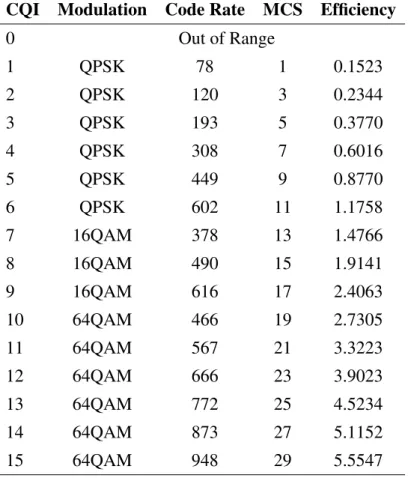
Measurements should be conducted to determine the optimal CQIs under different CSI conditions. The reported CQI is a number between 0 (worst case) and 15 (best case), as shown in Table 1.1, indicating the most efficient MCS which would lead to a Block Error Rate (BLER) of 10%. BLER measures the successful transmission rate at MAC and physical layer. Each CQI value in fact, is sharply associated with an MCS index, a spectral efficiency (b/s/Hz) and coding rate. Depending on the CQI a combination of modulation scheme, number of spatial streams and code rate MCS is selected [10]
Also there are two kinds of CQI reporting: periodic and aperiodic. Usually periodic CQIs are employed but if eNodeB needs channel quality information at a specific time, aperiodic CQIs are triggered. Aperiodic CQIs are mainly due to used loss of synchronization or handover and requested by the eNodeB by setting a CQI request bit on the Physical Downlink Control Channel (PDCCH).
To compute CQI in LTE downlink, channel quality parameters are measured and ag-gregated periodically. Although CQI is defined by the 3GPP, numerical computation and
1.3 Feedback mechanism in LTE 13
measurement represent an issue to address if they rely only on the CQI to perceive network status [11]. It is pretty obvious that Signal-to-interference-and noise Ratio (SINR), Reference Signal Received Power (RSRP), Reference Signal Strength Indicator (RSSI), Reference Signal Received Quality (RSRQ) play important roles to CQI measurement. Channel quality is represented by SINR which is usually computed for link adaptation along with packet scheduling, whereas RSRP and RSRQ are key values for handover making decision when intra E-UTRAN handover occur in LTE.
1.3.1
Reference Signal Received Power (RSRP)
For a particular cell, RSRP is defined as the average power (in Watts [W]) of the REs that carry cell-specific RSs within the considered bandwidth. RSRP measurement, normally are expressed in dBm. If a single UE is capable to receive multiple RS over different antenna ports, their combination is quite powerful and constructive to determine RSRP. For the purpose of RSRP determination a cell-specific reference signals R0 according [9] shall be used. Basically RSRP is a power measurement for a single subcarrier, a cell-specific signal strength related metric that is used as an input for cell resection and handover decisions. The value does not change with bandwidth or number of RBs currently assigned for data transmissions. So, this measurement would give you the lowest value comparing to other parameters and an idea of the strength of the signal a UE gets from the network, but it is not clearly stated which the signal quality is. RSRP is used mainly to rank among different candidate cells in accordance with the signal strength they provide.
1.3.2
Received Signal Strength Indicator (RSSI)
RSSI is the linear average of the total received power observed, including co-channel non-serving and serving cells, adjacent channel interference and thermal noise, within the measurement bandwidth over N RBs. RSSI is defined as the received wide band power, taking into account also thermal noise and noise generated in the receiver, within the bandwidth defined by the receiver demodulator. A reference point for the measurement should be the antenna connector of the single user.
1.3.3
Reference Signal Received Quality (RSRQ)
RSRQ measurement is a cell-specific signal quality metric. As RSRP measurement, this parameter is used mainly to provide ranking among different candidate eNodeB accordingly with their signal strenght and quality. This metric can be employed as an input in making
14 LTE Architecture and Radio Procedures
cell re-selection and handover decisions in scenarios, for example, in which the RSRP mea-surements are not sufficient to make reliable cell-re-selection/handover decisions. Reference Signal Received Quality (RSRQ) can be defined as:
RSRQ= N ·RSRP
RSSI (1.1)
where N is the number of RB’s of the E-UTRA carrier of the LTE carrier RSSI measurement bandwidth. The measurements in the numerator and denominator should be assessed over the same set of RBs. If higher-layer signaling indicates that a particular subframes is suitable for performing RSRQ measurements, then RSSI is taken over all OFDM symbols in the preferred subframes. The reference point for the RSRQ should be the antenna connector of the user. RSSI is used as a primary quantity to compute LTE RSRQ measurement. It is also clear that due to the inclusion of RSSI, RSRQ includes also the effect of signal strength and external interferences. It is also possible to observe that mathematically RSRQ is proportional to RSRP.
1.3.4
Signal to Interference plus Noise Ratio (SINR)
SINR is measured by UE on RB basis. UE’s granularity on SINR computation is per RB. It converts it into CQI and send it to eNodeB where it is adopted to select the most suitable MCS for user informations transmissions within a particular RB. SINR suggests which MCS to use for a particular Resource Block, the quantity of bits per symbol to be sent and the throughput to be obtained for that RB as well as the number of RBs to be allocated by eNodeB to UEs. SINR is defined as the ratio of the signal power to the summation of the average interference power from all the neighbor cells and the thermal noise. RSRP, RSRQ and RSSI measurements are defined by 3GPP, however SINR is not defined in 3GPP specifications, but fully addressed in UE vendors standards.
1.4
Throughput Estimation
Most commonly LTE in its physical layer adopts only FDD, to achieve in both uplink and downlink symmetrical bandwidth. To fully understand the potential of the FDD paired spectrum, LTE adopting it, is capable to achieve 20 MHz in throughput both in uplink and downlink. Also different bandwidth are presented: 1.4, 3, 5, 10, 15, 20 MHz [12] and play a key role in affecting throughput value. Each bandwidth is composed by a specific number of RBs which as previously stated represent the smallest unit of resources that can be allocated to a single user. When estimating throughput, it is needed to take into account that RBs
1.4 Throughput Estimation 15
Table 1.1 CQI per Coding Rate and Modulation
CQI Modulation Code Rate MCS Efficiency
0 Out of Range 1 QPSK 78 1 0.1523 2 QPSK 120 3 0.2344 3 QPSK 193 5 0.3770 4 QPSK 308 7 0.6016 5 QPSK 449 9 0.8770 6 QPSK 602 11 1.1758 7 16QAM 378 13 1.4766 8 16QAM 490 15 1.9141 9 16QAM 616 17 2.4063 10 64QAM 466 19 2.7305 11 64QAM 567 21 3.3223 12 64QAM 666 23 3.9023 13 64QAM 772 25 4.5234 14 64QAM 873 27 5.1152 15 64QAM 948 29 5.5547
16 LTE Architecture and Radio Procedures Table 1.2 UE Category and Maximum number of TB bits
Cat. Max Nr° TB bits 1 10296 2 51024 3 102048 4 150752 5 299552 6 301504 7 301504 8 299856 9 2998560 10 2998560 11 603008 12 603008
have a total size of 180 kHz in the frequency domain and 0.5 ms in the time domain. In time domain a TTI lasts 1 ms and consist of 12 subcarriers in the frequency domain, and since 12 OFDM subcarriers are used in a single RB, the bandwidth of a RB is 180 kHz. An OFDM subcarrier is 15 kHz, so with a bandwidth of 20 MHz the overall system deploys 18MHz/kHz = 1200 subcarriers. A 10% of the BW is reserved for guard band but this assumption is not valid with 1.4MHz wide carrier.
As previously stated MAC layer selects the modulation and coding scheme to configure the physical layer transmissions. The data at MAC level, are now in the shape of Transport Block Size (TBS), and the quantity of bits transferred in a 1ms transport block size strictly depends on the MCS and the number of resource blocks assigned to each UE [10].
User Category Information plays also a key role in maximizing throughput. Knowing a UE Category allow the eNB to transmit efficiently with all the UEs connected to it. The UE-Category defines the ability of the device in terms of DL/UL throughputs as specified in [13]. The maximum number transport block bits received within a TTI are shown in Tab. 1.2. For each TBS index specifies the TB dimension with regard to the number of RB assigned to that particular user. Higher modulation order corresponds to higher TBS dimension and MCS as shown in Table 1.3. With higher CQI values AMC uses higher order modulation but also in this case if a user is assigned with a larger number of RBs (NRBs) also uses a
1.4 Throughput Estimation 17 Table 1.3 Modulation and TBS Index Table
MCS Modulation Order TBS Index
IMCS Qm IT BS [0, . . . , 9] 2 [0, . . . , 9] [10, . . . , 16] 4 [9, . . . , 15] [17, . . . , 28] 6 [15, . . . , 26] 29 2 Reserved 30 4 Reserved 31 6 Reserved
bigger size of TBs. TB size depends in fact, from the data quantity to send to the user. If the amount of data to send is smaller than the selected TBS a smaller TB would be used. Knowing the size of the TB is straightforward to compute throughput [14]. If the eNodeB selects a MCS 20 and assigns 2 RBs based on the received CQI, from 1.3, it is evident that TBS index is equal to 18. Referring to the standard Table 7.1.7.2.1-1 of [10], to a index 18 with 2 RB corresponds a TB of 776 bit. We will have a single TB in a TTI (1ms):
Chapter 2
LTE MIMO Techniques
2.1
Improving Efficiency and Throughput with MIMO
MIMO has been adopted since many years in Wireless Networks, Wi-Fi standards in fact incorporated this technology since 802.11n. Multiple-Input Multiple-Output as the name suggests means that this technology allows to transmit at faster speeds by sending data through multiple receiving and transmitting antennas.
Using MIMO enhances the performance and enriches network connections compared to those adopting single-antenna techniques. Although its development dates back at ten years ago, only recently LTE networks involved MIMO in standard’s architecture. 3GPP technology in fact, has lastly evolved from the original Single-User transmission to a Single User MIMO (SU-MIMO) and a Multi User MIMO (MU-MIMO). LTE standard adopts multiple antenna techniques to improve system and radio network performance in a variety of different scenarios.
Multi-antenna technologies for reception and transmission at the eNodeB and in UEs in LTE today play a critical role in achieving the high performance offered to LTE. MIMO in fact, grants radio systems to reach higher performances by using multiple antennas at both their transmitters and receivers. From Release 10, LTE is able to implement up to eight antennas in downlink.
2.1.1
MIMO in LTE
With LTE MIMO can adopt the following configurations 2x2, 4x4 and 8x8, respectively for Transmit and Receiver Antennas. It can also be configured in two modes: Spatial Multiplex-ing and Transmit Diversity.
20 LTE MIMO Techniques Table 2.1 Different Antenna Schemes and Benefits
Tx Data
Streams Multiantenna Scheme Gain Benefits
One Transmit Diversity Diversity Gain
Link Robustness Coverage
Classical beam forming Antenna gain Coverage Capacity
Multiple Spatial Multiplexing Capacity Gain Spectral Efficiency Data Rates
In detail we have:
- Spatial multiplexing: the aim of Spatial Multiplexing is to transmit multiple different data streams over different parallel channels in order to increase data rate. it takes advantage of multi-path propagation to create a number of independent transmission channels between the transmitter and receiver, which enables two or more different signal streams to be transmitted simultaneously. Using the proper coding and signal processing informations can be extracted independently at the receiver side. This technique leads to an increase of the available throughput to an individual user or allows to multiplex data from multiple users. The maximum channels that can be multiplexed together is equal to the smaller of the number of antennas on both the transmitter and receiver side.
- Transmit Diversity: if a single user is taking advantage of single information flow Transmit Diversity can reach spatial diversity performances with the use of multiple antennas at the transmitter side. Several versions of the same information stream are sent to the receiver to prevent from fading and improve SINR gain. Transmit diversity techniques are adopted when a UE is experimenting the worst channel conditions. Both closed Loop and Open Loop are implemented to reach spatial diversity in LTE. With Open loop spatial diversity is in adopted blindly while with the use of closed loop control informations will be collected from UEs to properly weight antennas.
To efficiently maximize throughput using MIMO the network needs [15]: - Max Rich Scattering Conditions
- Configuring eNodeB to properly match channel conditions - Efficient assessment campaign carried out from UE
2.1 Improving Efficiency and Throughput with MIMO 21
22 LTE MIMO Techniques
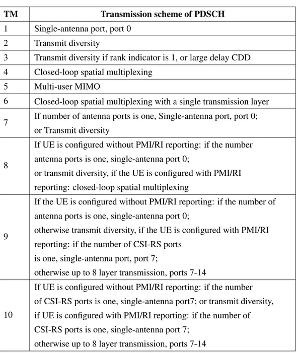
Table 2.2 Transmission Mode Table 7.2.3-0 - TS 36213
TM Transmission scheme of PDSCH
1 Single-antenna port, port 0
2 Transmit diversity
3 Transmit diversity if rank indicator is 1, or large delay CDD 4 Closed-loop spatial multiplexing
5 Multi-user MIMO
6 Closed-loop spatial multiplexing with a single transmission layer 7 If number of antenna ports is one, Single-antenna port, port 0;
or Transmit diversity
8
If UE is configured without PMI/RI reporting: if the number antenna ports is one, single-antenna port 0;
or transmit diversity, if the UE is configured with PMI/RI reporting: closed-loop spatial multiplexing
9
If the UE is configured without PMI/RI reporting: if the number of antenna ports is one, single-antenna port 0;
otherwise transmit diversity, if the UE is configured with PMI/RI reporting: if the number of CSI-RS ports
is one, single-antenna port, port 7;
otherwise up to 8 layer transmission, ports 7-14
10
If UE is configured without PMI/RI reporting: if the number of CSI-RS ports is one, single-antenna port7; or transmit diversity, if UE is configured with PMI/RI reporting: if the number of CSI-RS ports is one, single-antenna port 7;
2.1 Improving Efficiency and Throughput with MIMO 23
2.1.2
Mode Support in LTE
LTE supports different transmission mode configured for each UE. Mode is computed by both the capability of the user and also the capabilities of the serving eNodeB. All UEs are configured with a particular transmission mode to determine how to work with received data.
In the downlink, LTE uses technologies such as MIMO to achieve high data rates, however, it also offers fall-back technologies such as transmit diversity or Single Transmission Antenna and Single Receiver Antenna (SISO). For example, what it is commonly called SISO is implemented in TM1 (Transmission Mode 1). What is usually known as Diversity is identified with TM2. Eventually MIMO is introduced in TM4 and TM3.
A good summary of each Transmission Mode is shown in the following Table 2.2 or found in Table 7.2.3-0 of [10].
When Transmission Mode (TM)1 is in use the system transmits one single layer from each antenna port. RS signals combined with data are transmitted adopting the same antenna configuration.In order to demodulate the signal at receiver’s side only the RS related to that particular user is required. Although many antennas are simultaneously transmitting, with this technique a single UE is not aware of the actual number of parallel transmission and perceives data as transmitted in a single stream.
To improve SINR and robustness of transmission TM2 implements a classical MIMO. All data are in fact, sent via multiple antennas equipped with different modulation schemes and frequency configurations.
When TM2 is in use only a single layer is mapped with a space-frequency block code (SFBC) that relies on Alamouti code, and transmitted from multiple antennas. When two antennas are adopted, a frequency-based version of SFBC is used, while with a combination of four antennas, a mix of SFBC and frequency switched transmit diversity (FSTD) is used. In the case scenario of a UE moving at high speed, so when channel information is missing or when the channel rapidly changes, Spatial Multiplexing is implemented with TM3.
When TM4 is implemented each transmission is mapped to one or more layers. TM4 adopts a Closed Loop technique which grants channel estimation at the receiver.
Transmission mode 5 implements MU-MIMO enabling single-layer transmission to multiple users shareing the same frequency allocation. TM5 is also based on codebook-based closed loop spatial multiplexing.
TM 6 implements a variation of TM 4 closed loop spatial multiplexing using a single transmission layer. Here UEs estimate the channel and send the index of the most suitable precoding matrix back to the eNodeB. All eNodeBs send the precoded signal via all the antenna ports.
24 LTE MIMO Techniques
Fig. 2.2 SU-MIMO
With TM 8 Dual layer beamforming is adopted. Release 8 of the LTE standard defines beamforming with one layer. Release 9 specifies dual-layer beamforming. This allows eNodeB to proper configure weight for two different layers individually at the antennas so that beamforming can be used with spatial multiplexing for one or multiple UEs.
Release 10 adds Transmission Mode 9 allow to transmit with Up to 8 layer transmission. With the implementation of this mode up to eight layers can transmit simultaneously, eight physical transmit antennas are obviously needed in this case. The number of used layers can be assigned dynamically. Both single user and multi user MIMO is possible to adopt, dynamically switching between both modes without special signaling by higher layers.
2.2
SU-MIMO
The basic idea is to transmit multiple code-word to a single user in the same time-frequency interval so there is only one scheduled user per sub-band or channel. A code-word is defined as a Coded Transport Block, but in a wider sense we consider it as a single independently data stream. Spatial Multiplexing schemes can be classified according on if different streams are jointly (multiple code-word) or separately (single code-word) coded. When a single word is in use one coded and modulated TB is spatially multiplexed into several data streams. When multiple code-word are in use different coding and modulation schemas are in use for different transport block that are transmitted simultaneously. The mobile will adjust transmission rate and modulation coding scheme based on measurement report for each code-word adapting transmission for each of the code-code-words. Network will adapt transmission condition for each code-word independently [15]. From reported channel conditions and the
2.3 Open, Closed Loop - Spatial Multiplexing 25
UE’s ability to rapidly send detailed reports on channel conditions, an eNodeB can select among different SU-MIMO modes to implement. Different techniques are then enabled:
- Spatial Multiplexing Mode - A Open Loop
- B Closed Loop
- C Closed Loop Rank 1 - Transmit Diversity
2.3
Open, Closed Loop - Spatial Multiplexing
Both Open-Loop and Closed-Loop techniques together with Spatial Multiplexing are the main features to SU-MIMO’s great achievements in LTE throughput. With the adoption of spatial multiplexing techniques, separate data streams on N multiple antennas are created and its fullest potential is almost close to multiplying the highest throughput from UE by the adopted transmission rank, mainly equal to the number of separate streams transmitted. With spatial multiplexing, the eNodeB can group informations to be transmitted to a particular UE on a given sub-channel into multiple streams, called Layers. The number of layers is equal as the rank. Transmission rank is computed accordingly to channel conditions at the user side, as well as many more considerations such as eNodeB’s capabilities. Sending different data on each antenna, spatial multiplexing modes require rich scattering of multipath signals and best channel conditions. Under the right configuration, a UE can separate the signals from multiple transmitters, identified by different RS signals, and reconstruct separate information streams within same frequency block.
The simplest implementation for spatial multiplexing, allows a rank-2 transmission on a 2x2 MIMO antenna set-up will transmitting one layer from each Tx. Each layer reaches each UE along a different path. The UE can then reconstructs the layers using multiple information from all antennas.
With this technique, informations arrives encoded from higher level entities in one or more code-words. Each code-word represents one or more layers. In 2x2 MIMO, each code-word corresponds directly to a layer. Each layer is then mapped onto one or more antennas using a pre-coding matrix.
26 LTE MIMO Techniques
2.3.1
Open Loop
Adopting Open-loop technique no knowledge of the channel has to be shared with the transmitter. As a consequence, open loop implementations occur when the radio network layer cannot collect information or feedback from users to do any form of adjustment or when transmission quality is not good enough. This could happen for example when the UE is moving too fast and it is impossible to collect data regarding the channel state. In this case the eNodeB receives only a Rank Indicator (RI) and a CQI Report. A RI is defined as the number of data stream transmitted over the air in the same f and resource corresponding to the number of layers.
2.3.2
Closed Loop
Closed loop feedback allows a transmitting entity to retrieve information about channel conditions, provided by the users. If feedback is available, the transmitter can adjust its coding and modulation of the transmitted signals to take into account of the main channel characteristics, just to simplify the signal processing required at the receiver side and enable potentially greater performance gains. Closed-loop systems ask for channel knowledge at the transmitter side. On the other hand, unlike open loop, closed loop is adopted when the radio access network performs dynamic adjustment based on feedback from the user. In this case the eNodeB receives RI, Pre-coding Matrix Indicator (PMI) and CQI.
2.3.3
Transmit Diversity and Closed-Loop Rank-1 - Spatial
Multiplex-ing
Transmit Diversity and Closed-Loop Rank-1 Spatial Multiplexing techniques are imple-mented to boost signal to further improve throughput and capacity. A powerful solution could be experienced the best near the cell edge or in areas where user perceive low SINR or multipath conditions.
When using a Transmit Diversity Mode, MIMO the same information are sent from transmitting antennas with the aim to minimize channel interference. The UE receives data streams from both transmitting antennas at both receveing ones and reconstructs a unique stream from all multipath copies of the same signal. Multiple differentiated signals and multiple copies of the same informations decrease the percentage of losing data due to poor channel conditions.
With Closed-Loop Rank-1 Spatial Multiplexing, the eNodeB transmits a single set of data for both transmitting antennas. However, Closed-Loop Rank-1 Spatial Multiplexing
2.4 MU-MIMO 27
uses a linear pre-coding matrix to improve multipath conditions. When decoded at the receiver side, these signals contain the same informations. To combine constructively at the UE multiple signals a pre-coding matrix is adopting. Its role is to shape signala coming from each transmitting antenna. A good performance is achieved by matching a pre-coding matrix to the channel conditions experienced by users . When closed loop is adopted, the eNodeB collects precious information about channel propagation conditions and choose the best among the multiple pre-coding matrices defined for 2x2 MIMO. Taking a look to more conventional Transmit Diversity techniques, Closed-Loop Rank-1 Spatial Multiplexing allows to increase SNR significantly.
2.4
MU-MIMO
In MU-MIMO, multiple different data streams are sent to spatially separated users using the same channel configuration. Each user has been equipped with multiple receivers antennas. Adopting MU-MIMO the whole system capacity achieves a strong gain, even though no increase in UE’s throughput has been demonstrated. To achieve better results rich scattering conditions are mandatory for all UEs to decode data streams.
LTE adopts a pre-coded configuration fo MU-MIMO with several feedback collected from users. Both transmitters and receivers antennas are aware of the set of configured PMIs. Precoding in LTE is implemented maninly for two purposes:
- reduce interference among transmitted signals at the receiver side which is significantly with orthogonal modulations when multiple parallel channels are in use;
- mapping the number of multiplexed streams to the number of transmitting antennas. Usually, the same pre-coding configurations is used for beam forming and precoded spatial multiplexing in LTE.
2.5
MIMO Reporting
Since there are mutliple transmission modes in LTE and each one is corresponding to certain multiple antenna techniques CQI reports can be divided into three levels:
- wide-band,
- eNodeB-configured sub-band feedback, - UE-selected sub-band feedback.
28 LTE MIMO Techniques
Fig. 2.3 MU-MIMO
Table 2.3 TM 1,2,3,4 vs CSI
Transmission Mode Payload
1. Single-antenna port; port 0
UE selected sub-band CQI + wide-band CQI or
Higher Layer Configured wide-band and sub-band CQI, no PM 2. Transmit diversity UE selected sub-band CQI + wide-band CQI or
Higher Layer Configured wide-band and sub-band CQI, no PMI 3. Open-loop spatial
multiplexing
UE selected sub-band CQI + wide-band CQI or
Higher Layer Configured wide-band and sub-band CQI, no PMI 4. Closed-loop spatial
multiplexing
Wide-band CQI per codeword + PMI for each sub-band or
UE selected sub-band and wide-band CQI per codeword + PMI or Higher Layer Configured wide-band and sub-band CQI + PMI
2.5 MIMO Reporting 29
The wide-band report provides an overall CQI value for the downlink bandwidth and with this mode as in the periodic reporting, the UE only reports a single value for the whole bandwidth. In the eNodeB-configured sub-band feedback, two kinds of CQI specis are collected, one for the whole system and one for the preferred sub-bands. In the calculation of sub-band CQIs, it is assumed that each transmission occurs only in the preferred bands. In a UE-selected sub-band feedback, as in the eNodeB-configured one, two different species of CQIs are collected, one wide-band CQI value for the whole system bandwidth and one reporting the average measured CQI in M selected sub-bands, each of a specific size. With a selected sub-bands CQI report, the user divides the system bandwidth into N multiple sub-bands, selects only a set of preferred N sub-bands available then reports a single CQI value for the wide-band and one CQI value for the selected set, assuming transmission only over the preferred N bands. The higher layer configured sub-band report provides the highest granularity [16].
For each transmission mode so, certain combinations of CQI report are defined based on periodic/aperiodic, wide-band/UE selected sub-band/higher layer configured sub-band also depicted in Tab.2.3.
If closed loop MIMO is used, PMI and RI are also collected and reported. PMI suggests the codebook an eNB should use for transmission using multiple antennas computed on the evaluation of received reference signal. RI indicates the number of transmission layers that the UE can receive. In 4G networks, UEs use RI to disclose information about layer mapping. RIs are adopted when open loop transmission are in use as well as in closed loop transmission modes. Spatial multiplexing can be supported only when RI is more then 1. CQI is reported for each codeword when the system works with spatial multiplexing.
30 LTE MIMO Techniques
Chapter 3
LTE in Unlicensed Bandwidth
3.1
Brief Overview of LTE and Wi-Fi Access Techniques
Wireless networks are generally classified in cellular networks and Wi-Fi networks. Each network is characterised by specific elements and allocated spectrum. Cellular networks use mainly licensed bandwidth while Wi-Fi technologies use unlicensed spectrum. Recently the idea of LTE working in the unlicensed spectrum to achieve greater efficiency has been exploited. Since LTE has been designed to operate in licensed bands assuming the absence of any interference its MAC layer is not suitable to work in unlicensed bandwiths. Wi-Fi standard, on the other hand, adopts the LBT approach, along with collision avoidance techniques, that allows to share the spectrum in use with other Wi-Fi other technologies in a fair way. In this chapter, a brief overview of Wi-Fi and LTE MAC layers is given.
3.1.1
Wi-Fi
In 1997 the first version of the IEEE 802.11 standard was published. To widen wireless spectrum, without the need for a government license, in 1985 the Federal Communications Commission (FCC), America’s telecoms regulator gave birth to Wi-Fi, the short-range wireless broadband technology.
With 802.11 both ad hoc networks and infrastructure networks can be deployed. Infras-tructured topologies consists of one or more independent cells, each of which is managed by a base station called Access Point (AP).
AP usually are interconnected between them and form a Distribution System. The connected access points are usually in an Extended Service Set (ESS). An ESS is a set of connected Basic Service Sets (BSSs). A BSS is a set of all stations that can communicate with each other at physical layer.
32 LTE in Unlicensed Bandwidth
Ad hoc networks on the other hands, lets two or more devices communicate with each other directly and each device can access each other’s resources directly through a simple point-to-point wireless connection.
Since 1997 also, several new physical layers have been introduced by various amendments Table 3.1 to make higher transmission rates available. 802.11 at first dealt with three different transmission techniques both with 1 or 2 Mbps rate. Since these performances were not sufficient the committee got back to work and in 1999 two new standards were approved: 802.11b and 802.11a. 802.11b was compatible with all the previous standards and added two new main rates 5.5 Mbps e 11 Mbps. 802.11a was adopting a 64QAM modulation and could reach also 54 Mbps thus using the 5 GHz bandwidth. So after two years the committee proposed its variation 802.11g that led to achieve 54 Mbps in the 2.4 GHz band.
Since Wi-Fi operates in the unlicensed bandwidth it requires spread spectrum modulation to be in use. These techniques allow to spread the signal on to a much larger bandwidth then required, letting the signal appear as noise noise to other devices. Spread spectrum first was developed for use by the military because it uses wideband signals that are difficult to detect and that resist attempts at jamming. Two different examples of spread spectrum are: Frequency Hopping Spread Spectrum (FHSS) and Direct Sequence Spread Spectrum (DSSS). In the first case the signal is always switching a carrier among different frequency, using a pseudorandom sequence known to both transmitting and receiving device. With the second the signal is divided into smaller pieces, each associated with a frequency channel. Data signals at transmission points are combined with a higher data rate bit sequence, which divides data based on a spreading ratio. The chipping code is a redundant bit pattern associated with each bit transmitted and this helps to increase the signal’s resistance to interference. If any bits are damaged during transmission, the original data can be recovered due to the redundancy of transmission. Apart from 802.11b, all the amendments listed in Table 3.1 use OFDM as the underlying modulation scheme.
MAC protocol for Wi-Fi networks has been obviously designed to be independent from any specific physical layer characteristic. It should be also efficient both for periodic and bursty traffic.
All the stations belonging to the same BSS use the same channel (or channels, starting from 802.11n) to transmit and receive frames. Stations can access the wireless channel according to two basic schemes:
- Point Coordination Function (PCF) - Distributed Coordination Function (DCF)