UNIVERSITY
OF TRENTO
DIPARTIMENTO DI INGEGNERIA E SCIENZA DELL’INFORMAZIONE
38123 Povo – Trento (Italy), Via Sommarive 14
http://www.disi.unitn.it
FUTURE TRENDS ON NANOANTENNAS SYNTHESIS
D. Franceschini, M. Donelli, R. Azaro, and A. Massa
January 2011
Future Trends on Nanoantennas Synthesis
D. Franceschini, M. Donelli, R. Azaro, and A. Massa Dep. of Information and Communication Technologies University of Trento Via Sommarive 14, 38050 Trento, Italy {davide.franceschini, massimo.donelli, renzo.azaro}@dit.unitn.it, [email protected] Abstract—This paper aims at outlining some possible future challenges and solutions in nanoantennas design in the range of applications going from millimeter to nanometer scale. The growing interest for such systems, both in the field of miniature sensors and for applications in the visible and near infrared frequencies, requires effective design procedure in order to satisfy the desired specifications and the feasibility constraints. In such a context, the paper presents some non‐intuitive methodologies based on the swarm intelligence that could provide effective tools for nanoantennas synthesis. Nanoantennas; nanotechnology; nanowires; particle swarm optimization; antennas synthesis. I. INTRODUCTION The miniaturization is the challenging issue of nowadays and future research trends in a variety of applied sciences going form miniaturized wireless sensor networks and UWB systems to nanosystems operating at visible and infrared frequencies in the field of optical circuits and biomedical devices. As far as the centimeter and millimeter applications are concerned, the concept of nanoantenna is usually used in a broad sense since there is a growing need of miniaturized transmitting systems. In particular, in the field of Ultrawideband (UWB) communication devices ([1], [2]), of smart miniature sensors (“smart dust”) [3] and of nanodevices, the compactness of the transmitter is a key issue since usually such systems may employ a wavelength much larger than the device itself [4]. In fact, although resonant half‐wavelength dipoles or quarter‐wavelength monopoles could be acceptable for some applications employing centimeter and millimeter waves, modern compact devices require the use of the so called “electrically small antennas” (e.g., [5], [6]), which are radiating structures smaller than a quarter‐wavelength. Their drawback is certainly represented by the radiation inefficiency that becomes non‐negligible when low power devices are used, as in UWB applications and smart sensors. Therefore, there is still the need of developing efficient miniature radiators and some designs of nanoantennas [1] have been recently proposed in the context of ultra high and microwave frequencies applications.When moving from the above mentioned applications to the field of nanotechnologies, recent research trends have shown a great interest in nanometer‐scale antennas for optical and infrared applications [7] concerning medical imaging, devices for detecting chemical and biological agents and nanosensors. One of the most addressed challenges has concerned the schemes to improve the mismatch between optical wavelength and nanoscale targets [8]. Among the different solutions, the most investigated exploit the intense fields created coupling small metallic spheres or bowtie‐type antennas [8]. The latter is built with two metallic triangles separated by a small gap whose size can control the resonance behavior. Moreover, recent researches have shown that tiny wires and metallic spheres can be arranged in various configurations to form nanoantennas and arrays of nanoantennas. Finally, also the circuits concepts have been extended to the optical frequencies when such waves interact with metallic and non‐metallic nanoparticles [9], [10]. The models used at lower frequencies cannot be directly transposed to optical frequencies since conductive materials behave differently (e.g., their permittivity could have a negative value).
Whatever is the selected structure used to realize nanoantennas, the control of its characteristic parameters during the fabrication allows to tune the resonant frequency according to a particular application. Therefore, the availability of rigorous closed form solutions describing the resonance phenomena in nanostructures would be really helpful. Notwithstanding several works are pursuing solutions towards this direction, closed form expression have been obtained only for basic elements as for examples single nanoshells (see [11] and the references therein). On the contrary, when dealing with more complex or randomic configuration, such as arrays composed of nanospheres or nanowires, closed form models of the resonance phenomena are usually not available.
Accordingly, because of the lack of guidelines for the synthesis process, computational tools allowing a non‐intuitive design of nanoantennas are potentially of great interest. Certainly, such approaches need of careful investigation since each optimization algorithm has to deal with severe computational limits due to the expensive discretizations that have to be used in the numerical modeling of the different nanostructures. However, it is challenging to pursue researches in this direction in order to match
available efficient optimization tools usually employed in traditional antenna synthesis with the design issues related to nanoantenna systems.
In such a context, the aim of this paper is to outline possible frameworks of applications where optimization algorithms could be successfully exploited, especially where complex or non‐standard design requirements are involved. In particular, one of the last powerful stochastic optimization techniques inspired by the social behavior of the insects swarms [12]‐[16] will be considered. Such a particle swarm optimizer (PSO) has been selected because of some properties that make it very appealing:
• the easy implementation of its simple algorithmic structure characterized by a single operator, the velocity updating; • the easy calibration of the main parameters for controlling the behavior of the algorithm makes the PSO very suitable for
a proper customization in a specific framework of applications. Certainly, the optimal configuration of the control parameters for optimization problems in the field of nanotechnology has not been investigated in the related literature (to the best of author knowledge). For this reason such an issue represents a challenge for future researches;
• the ability to prevent the stagnation [16] by means of a suitable control of the inertial weight.
The paper is organized as follows. In Sect II, some possible design applications concerned with centimeter, millimeter and nanometer scale antennas will be outlined, while a detailed explanation of the PSO algorithm will be given in Sect. III. Finally, some conclusions and future developments will be reported in Sect. IV. II. OPTIMIZATION PROBLEMS IN NANOANTENNAS DESIGN In this Section, some possible applications of the evolutionary design methodology will be preliminary discussed. In particular, two categories of antennas will be considered, starting from centimeter and millimeter scale antennas and successively moving toward the optimization problem of antennas at nanoscale. A. Antennas at centimeter and millimeter scale In [1] the use of a nanoantenna has been proposed for UWB applications. Such a device it is built by two enclosures separated by a small gap so that a structure similar to a dipole can be obtained (Fig. 1). Moreover, to further miniaturize the dimensions of the device, a dielectric coating has been also introduced. Figure 1. Configuration of a UWB nanoantenna. The efficiency of such an antenna depends on the relative size of the inner capacitance and the hemispherical capacitance that have to be designed together with the value of the dielectric permittivity ( ) of the external coating. The synthesis of the configuration sketched in Fig. 1 could efficiently transmit UWB impulses in the frequency band 3‐10GHz by means of a 1mm‐size device [1]. co r
ε
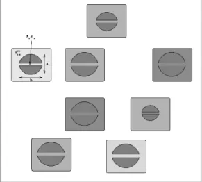
Certainly, more degrees of freedom in the antenna synthesis could be introduced by combining the spherical nanoantennas in uniform and non‐uniform arrays (Fig. 2). By so doing, the parameters to be designed unavoidably increase, since such a project would involve the optimization of: • the array dimension, N; • the position of each nanoantenna, (xn,yn) in the case of a bidimensional array; • the sizes of the inner and outer capacitances of each array elements, in n C and Cnout;• the dielectric coating of each array element, co n r ,
ε
.The design and the synthesis of arrays of nanoantennas could lead to more efficient radiating systems, provide more flexibility in the impedance matching and beam shaping. However, this problem requires a suitable tool for the optimization of the key parameters of the nanoarray, which are not always easy to predict analytically and in an intuitive fashion. Therefore, in such a context, the exploitation of an evolutionary synthesis methodology allows the exploration of new configurations and to obtain optimized performances. Figure 2. Example of a nanoarray configuration. B. Antennas at nanometer scale
Following the same approach, radiating systems at nanometer scale could be obtained arranging arrays of elementary structures. In the field of nanotechnologies, such basic structures are represented by nanowires and nanoparticles to be synthesized in different configurations of active and passive elements.
Figure 3. Possible configuration of plasmonic and non‐plasmonic nanoparticles
As pointed out in [9], [10] nanoantennas for nanometer‐sized transmitting and receiving systems could exploit combination of non‐plasmonic and plasmonic nanospheres. The former are known to have a positive dielectric permittivity (
ε
>0) and a nanoscale equivalent circuit formed by a nanocapacitor and a nanoresistor, while the plasmonic nanoparticles are characterized by a negative dielectric permittivity (ε
<0) referable to a nanoinductor and a nanoresistor at the optical regime. As far as the synthesis of nanoantennas and nanoarrays is concerned, several parameters have to be taken into consideration during the design process. For example, if one should synthesize the structure depicted in Fig. 3, the available degrees of freedom to exploit in order to meet the desired specifications are represented by: • the displacement (location) of the nanoparticles;• the characteristic of the materials;
• the radius of the nanospheres (influence the capacitive and inductive behaviors of the nanospheres); • the combinations of materials in case of inhomogeneous nanospheres.
Also for this class of problems, the multidimensional nature of the parameters to be designed makes the synthesis very challenging for an evolutionary optimization procedure. Moreover, the behavior of the stochastic algorithms for nanoscale problems has not been investigated yet. In the authors’ opinion, the calibration procedure (e.g., [16]) carried out for centimeter and millimeter scale optimization problems in electromagnetics should be assessed and, in case, the definition of the evolutionary operators and quantities should be customized for design problems involving nanoelements.
III. THE PSO ALGORITHM
A. Problem statement The PSO algorithm is a multiple‐agent optimizer that is suitable for problems that require a non‐intuitive design process. This often happens when the searched configuration that meets the project specifications belongs to a Figure 4. Sketch of the swarm intelligence. multidimensional solution space. In such cases a possible approach is to recast the synthesis procedure into an optimization one defining a suitable functional to be minimized
{ }
2 2 ) ( Λ Λ − Λ = Φ u u In the previous expression the parameter Λ represent a general objective to be reached by the optimization procedure, while{ }
u Λ is a suitable operator that links a certain parameter configuration u to the objective to be pursued. According to such a strategy, eq. (1) represents a method to measure how much a set of parameters is close to the design specifications. Moreover, eq. (1) can be also exploited to guide the optimization process of the PSO strategy, which consists of an iterative execution of the set of operations described in the following. B. Basic definitionsFirst of all, let us consider a set of particles able to change their state with time. Such particles fly around in the multidimensional solution space and vary their positions according to their own experience and the experience of neighboring particles (exploiting the knowledge of best positions encountered by themselves and their neighbors).
In the particle swarm algorithm, the particles are organized in a swarm of S individuals Σ=
{
σ
s;s=1,...,S}
( being thedimension of the set of trial solutions), each of them characterized by a position
S
s
u in the solution space (i.e., the s‐th trial solution of the antenna parameters)
us =
{
us,p;p=1,...,P}
and by a velocity vsvs =
{
vs,p;p=1,...,P}
which represents the capability of the s‐th particle to fly from the current position uks (where k is iteration index of the
minimization process) to the successive position uks+1 in the solution space (Fig. 4).
C. Optimization process
As far as the iterative procedure is concerned, it is composed by a set of steps repeated for each of the K iterations:
initialization, fitness evaluation, iteration updating, convergence check, velocity updating, boundary conditions check, position updating. 1) Initialization During the initialization phase (k=0) a swarm of S particle
{
sk s S}
k ,..., 1 ; = = Σσ
is randomly generated and to each particle a position uks and a velocity vks are associated. The former is defined by randomly selecting a value with uniform probability over the search space of the p‐th parameter(
uks,p∈[
χ
minp ,χ
pmax]
)
defined on the basis of the available a priori information. Analogously, a random value belonging to interval[
−V ,p Vp]
is assigned tok p s
v , , being Vp a threshold value. Eventually, the
inertial weight
ω
k is also set.2) Fitness evaluation
The particles are ranked according to the fitness value provided by the cost function (1), Φks =Φ
( )
uks . Then, the fitness valueof each particle is compared to the best fitness that the particle has ever attained at any iteration up to current one,
( )
{ }
( )
h s k h k s u b = Φ Φ − = − 1 ,..., 1 1min and update the “pbest” trial solution bks =uks if Φ
( ) ( )
uks <Φbks−1 . Successively, the optimal particle of the current iterationσ
optk is looked for, and its position ukopt = mins{ }
Φ( )
usk updates the “gbest” particle of the swarm gk =ukopt if Φ( ) ( )
ukopt <Φgk−1 .3) Iteration updating
Once the “p‐best” and the “g‐best” are determined, the iteration index is updated (k = k+1).
4) Convergence check
If the maximum number of allowed iterations K (i.e., k >K ) is reached or a threshold for the fitness value (i.e.,
( )
≤γ
Φ k
g ) is crossed, then uopt =gkand the minimization process is stopped. Otherwise, go to phase 5).
5) Velocity updating
According to the configuration of the global best gk and of the individual best particles bks , the velocity vks of each particle is updated according to the following equation [12]:
in which and are uniform random numbers between 0 and 1; and are two positive constants called “acceleration coefficients”. They represent the weight of the “cognition” and “social” part that pulls
1
r r2 C1 C2
s
σ
from uks toward the “pbest” bks and the “gbest” gk positions [12], respectively.6) Boundary conditions check
Excessively large step sizes in the particle’s fly can be reduced by clamping vsk,p to a specified maximum value (according
to the reference literature [12], [13]). Moreover, the search space of the swarm is limited to the physically admissible solution space by changing the sign of (“reflecting wall” boundary condition [16]) when turns out to be out of the physical range. p V k p s v , usk,p 7) Position updating After updating the velocity values, the position of the s‐th particle
σ
sk is changed according to the following expression usk,+p1 =uks,p +vsk,+p1 then the optimization procedure continues to the step 2). The main steps of the PSO algorithm are shown in the flowchart of Fig. 5. Figure 5. PSO flowchart.IV. CONCLUSIONS
The paper has outlined some possible future challenges concerning the design and the synthesis procedure of nanoantennas and nanoarrays for millimeter and nanometer scale applications. The interest in such a topic is due to the growing efforts in the miniaturization of the devices and sensors (sensor networks and smart dusts) and in the development of nanodevices for transmitting and receiving signals at optical and infrared frequencies. Although the nanoantennas are usually synthesized by means of basic and somewhat simple elements, their design (especially when combined in array configurations) usually involves the optimization of a multidimensional parameter space to be solved by means of proper global optimization tools. These methodologies can afford the design of non‐intuitive nanoantennas configurations even though analytical and rigorous model are not available. In such a context, the particle swarm optimization has been presented as a useful and versatile methodology able to deal with complex optimization problems thanks to the exploitation of the swarm intelligence in a cooperative fashion. Moreover, some possible applications and future research directions of optimization problems at nanoscale level have been presented pointing out strategies and array configurations to be considered in order to obtain efficient nanoantennas systems for the desired applications.
ACKNOWLEDGMENT
This work has been supported in Italy by Center for Research And Telecommunication Experimentations for NETworked
communities (CREATE‐NET) and by “ Study and Development of Innovative Smart Systems for Highly Reconfigurable Mobile
Networks”, Progetti di Ricerca di Interesse Nazionale – Miur Project COFIN 2005099984_001. REFERENCES
[1] H. G. Schantz, “”Nanoantennas: a concept for efficient electrically small UWB devices,” in Proc. 2005 IEEE International Conference on UWB, Zurich, Switzerland, p. 264‐268, 5‐8 Sptember, 2005 [2] S. Bagga, A. V. Vorobyov, S. A. P. Haddad, A. G. Yarovoy, W. A. Serdijn, and J. R. Long, “Codesign of an impulse generator and miniaturize antennas for IR‐ UWB,” IEEE Trand. Microwave Theory Tech., vol. 54, pp. 1656‐1666, 2006 [3] G. P. Frost, “Sizing up smart dust,” Computing in Science & Engineering, vol. 5, pp. 6‐9, 2003. [4] H. G. Schantz, The art and science of ultrawideband antennas. Norwood, MA: Artech House, 2005. [5] G. A. Thiele, P. L. Detweiler, and R. P. Penno, “On the lower bound of the radiation Q for electrically small antennas,” IEEE Trans. Antennas Propagat., vol. 51, pp. 1263‐1269, 2003. [6] R. Azaro, G. Boato, M. Donelli, A. Massa, and E. Zeni, “Design of a Prefractal Monopolar Antenna for 3.4–3.6 GHz Wi‐Max Band Portable Devices,” IEEE Antennas Wireless Propagat. Lett., vol. 5, pp. 116‐119, 2006. [7] D. A. Genov, A. K. Sarychev, V. M. Shalaev, and A. Wei, “Resonant field enhancements form metal nanoparticles arrays,” Nano Letters, vol. 4, pp. 153‐158, 2004.
[8] P. J. Schuck, D: P. Fromm, A. Sundaramurthy, G. S. Kino, and W. E. Moerner, “Improving the mismatch between light and nanoscale objects with gold bowtie nanoantennas,” Phys. Review Lett., vol. 94, 017402, 2005.
[9] N. Engheta, A. Salandrino, and A. Alù, “Circuit elements at optical frrequencies: nanoinductors, nanocapacitors, and nanoresistors,” Phys. Review Lett., vol. 95, 095504, 2005.
[10] N. Engheta, A. Alù, and A. Salandrino, “Nanocircuit elements, nano‐transmission lines and nano‐antennas Using Plasmonic Materials in the optical domain,” in Proc. 2005 IEEE Int. workshop on Antenns Technology, pp. 165‐168, 2005. [11] M. Alam, and Y. Massoud, “A closed form analytical model for single nanoshells,” IEEE Trans. Nanotechnology, vol. 5, pp. 265‐272, 2006 [12] J. Kennedy and R. C. Eberhart, “Particle swarm optimization,” in Proc. IEEE Int. Neural Networks Conf., vol. IV, Perth, Australia, pp. 1942‐1948, 1995. [13] J. Robinson, S. Sinton, and Y. Rahmat‐Samii, “Particle swarm, genetic algorithm, and their hybrids: Optimization of a profiled corrugated horn antenna,” in IEEE AP‐S Int. Symp. Dig., vol. 1, 2002, pp. 314–317. [14] D. Gies and Y. Rahmat‐Samii, “Particle swarm optimization for recon‐figurable phase‐differentiated array design,” Microwave Opt. Technol. Lett., vol. 38, pp. 168–175, 2003. [15] D.W. Boeringer and D. H.Werner, “Particle swarm optimization versus genetic algorithms for phased array synthesis,” IEEE Trans. Antennas Propagat., vol. 52, no. 3, pp. 771–779, 2004. [16] J. R. Robinson and Y. Rahmat Sami, “Particle swarm optimization in electromagnetics,” IEEE Trans. Antennas Propagat., vol. 52, no. 2, pp. 397–407, 2004.