Stability analysis of second order pulsed Raman laser in dispersion
managed systems
Salih K. Kalyoncu
1, Shiming Gao
1, En-Kuang Tien
1, Yuewang Huang
1, Dogukan Yildirim
1,
Enver Adas
1, Stefano Wabnitz
2and Ozdal Boyraz
1, 31
EECS Department, University of California, Irvine, 92697, USA
2
Dipartimento di Elettronica per l’Automazione, Università di Brescia, 25123 Brescia, Italy
3EE Department, founding member, Istanbul Sehir University, Istanbul, Turkey
Email:
[email protected]
ABSTRACTWavelength tunable synchronous pulse sources are highly desirable for spectroscopy and optical diagnostics. The common method to generate short pulses in the fiber is the use of nonlinear induced spectral broadening which result in soliton shaping in anomalous dispersion regime. However, to generate ultra-short pulses, broadband gain mechanism is also required. In recent years, Raman fiber lasers have retrieved strong interest due to their capability of serving as pump sources in gain-flattened amplifiers for optical communication systems. The fixed-wavelength Raman lasers have been widely studied in the last years, but recently, much focus has been on the multi wavelength tunable Raman fiber lasers which generate output Stokes pulses in a broad wavelength range by so called cascaded stimulated Raman scattering. In this paper we investigate synchronous 1st and 2nd order pulsed Raman lasers that can achieve frequency spacing of up to
1000cm-1 that is highly desired for CARS microscopy. In particular, analytical and numerical analysis of pulsed stability
derived for Raman lasers by using dispersion managed telecom fibers and pumped by 1530nm fiber lasers. We show the evolution of the 1st and 2nd order Stokes signals at the output for different pump power and SMF length (determines the net anomalous dispersion) combinations. We investigated the stability of dispersion managed synchronous Raman laser up to second order both analytically and numerically. The results show that the stable 2nd order Raman Stokes pulses
with 0.04W to 0.1W peak power and 2ps to 3.5ps pulse width can be achieved in dispersion managed system. Keywords: Second order pulsed Raman laser, dispersion managed system, stability analysis, variational analysis.
1. INTRODUCTION
For spectroscopy and optical diagnostics, phase coherent and wavelength tunable synchronous pulse source is a great demand. The nonlinear induced spectral broadening in an anomalous dispersion regime is the widely used method to generate short pulses in the fiber by so called soliton compression [1]. Stimulated Raman scattering with a wide gain bandwidth of ~6THz has an ability to generate femtosecond pulses. Additionally, Raman gain can be generated at any wavelength in a nonlinear medium. Up to date, the Fiber Raman Lasers (FRL) have attracted much attention for their wide spread applications such as pump sources in gain-flattened amplifiers and tunable sources for characterization of optical devices [2-3]. In particular, multi wavelength tunable fiber Raman lasers are highly desirable to generate Stokes pulses at a broad wavelength range. In chemistry and biological applications, with higher order cascaded pulsed Raman lasers with a broad frequency spacing which is highly desirable for CARS microscopy are generated [4]. In this paper, we studied the stability analysis of the 1st and the 2nd order pulsed Raman lasers with frequency tuning range up to
1000cm-1. Particularly, detailed numerical analysis is conducted to investigate the stability regime of the Stokes pulses
up to second order in a dispersion managed system pumped by 1530nm fiber laser. Stable Stokes pulses are generated with respect to different pump power and single mode fiber (SMF) length that consists of dispersion managed (DM) system to form the cavity. Variational analysis is also derived to analytically analyze the steady state dynamics of the Stokes pulses inside the cavity and to predict the output pulse parameter by solving ordinary differential equations with a periodic boundary conditions which seems an alternative to time consuming numerical simulations. The analytical results are compared with simulation results to show good agreement with the derived equations. The results illustrate that the stable 2nd order Raman Stokes pulses with 0.04mW to 0.1W peak power and 2ps to 3.5ps pulse width can be
To generate s is the utmost hence it is no walk off and
System is [7] that main single mode (HNLF) piec restrict our a single mode Fibe Nonlinearit Raman co Zero disper L In order t generate stab system havin satisfies the stretcher (del 2 stable pulsed l t important par ot possible to m perform stabil Figure 1 s pumped by 15 nly consists of fiber (SMF) ces which has nalysis for com fiber (SMF) us er loss (α) ty coefficient (γ Aeff oefficient (gR) rsion (λ0)/ slop Length to raise the ne ble soliton like ng net anomalo described des lay line) in one
2. SIMULA asers by Rama rameter. Most o maintain a reas lity analysis fo 1. Designed set u 530nm Mode L two cascaded for pulse shap a nearly zero mmercially ava sed in the simu Table 1. The HNL 0 γ) 11.5 1 3.4 pe 1530nm / L=8m et dispersion to pulses. Thus, ous dispersion. sign criteria. T e of the ring cav
ATION SETU
an process, disp of the commer sonable walk-o
llowing experi
up (1a) and the d
Locked Laser w sections, the d ping. Dispersio
dispersion an ailable fibers fr ulations are sum
e characteristics LF (+) slope 0.9 dB/km 5 (1/W-km) 1.7 (μm2) 4 (1/W-km) / 0.01(ps/nm2k m (4 section) o anomalous re each round trip . Figure 1b illu The overlappin vities to match UP and ANA persion manag rcial DSFs and off (overlappin imental setup i dispersion manag with 10ps puls dispersion man on managemen d dispersion s from different v mmarized in Ta
of the fibers use
H 1 3 km) 1530nm L= egime, SMF is p can be assum ustrates the dis ng of Stokes p h the pump repe
0 -5 0 5 10 15 20 25 30 35 40 D is p er si on ( p s / k m -n m ) ALYTICAL E gement of pump d SMFs have hi ng of pulses) th s being investi
ged system for e
e width. The la naged (DM) sy nt is formed b lope in a perio vendors. The c able 1. ed in the simulati HNLF (-) slope 0.9 dB/km 1.5 (1/W-km) 11.7 (μm2) 3.4 (1/W-km) m / -0.01(ps/nm =8m (4 section) s cascaded wit med as a period spersion profile pulses at the b etition rate. 20 4 Dispers L=8m EQUATIONS p, first order an igh dispersion hrough the pro gated, Figure 1
each Stokes puls
aser cavity is d ystem as the ga by cascading odic configura characteristics o ions [6]. m2km) 1310n ) th the dispersio d of the modifie e for each Stok beginning is sa 0 60 sion Profile of D Length (m) S nd second orde values and slo opagation. To e 1a. es (1b). designed as pro ain mechanism highly nonline ation. In partic of the HNLF’s SMF 0.2 dB/km 2 (1/W-km) 50 (μm2) 0.8(1/W-km) nm / .076(ps/n L=20m-100m on managed sy ed dispersion m kes order in fib atisfied by ins 80 100 M System DM for 1stSto DM for 2ndSto LSMF er pulses opes, and eliminate oposed in m and the ear fiber cular, we s and the ) nm2km) m ystem to managed bers that serting a 120 okes okes
The propagation of Stokes pulses at steady state can be modeled by using variational analysis method which assumes the signal maintains its shape even though its power, pulse width and chirp changes in a continuous manner and remains same periodically after each round trip. The well known equations describing the evolution of single pulse parameters in variational method [5] can be modified by taking signal to signal interactions into consideration such as Raman amplification, cross phase modulation (XPM) and walk off as a perturbation in the system. In particular, the physical effects of XPM and the walk off on the chirp evolution, pump depletion, and gain reduction become more dominant [8]. The modified analytical equations for the pulse parameters, power (P), pulse width (T), chirp(C) and the temporal position (t) assuming all the pulses having Gaussian shape are:
2 1 1 1 1 exp p s p R p p p p p p dP P g P P dz T
t
t
t
d
T
dz T
λ
α
λ
= − −⎢
⎡
−⎛ ⎞
⎜ ⎟
⎤
⎥
+ ⎜
⎛
⎜
⎞
⎟
⎟
⎛
⎜
⎜
⎞
⎟
⎟
⎢
⎝ ⎠
⎥
⎝
⎠
⎝
⎠
⎣
⎦
(1) 1 2 p pt
d
w
dz T
⎛
⎞
=
⎜
⎟
⎜
⎟
⎝
⎠
(2) 2 1 1 1 1 1 2 1 1 1 2 2 2 1 1 1 2 1 1 exp s exp R p R s p dP P dT P g P P g P P dz T dzt
t
t
d
t
T
T
T dz T
λ
α
λ
= − +⎡
⎢
−
⎜ ⎟
⎛ ⎞
⎤
⎥
−⎢
⎡
−
⎜
⎛
⎟
⎞
⎥
⎤
−+
⎜ ⎟
⎛ ⎞
⎛ ⎞
⎜ ⎟
⎢
⎝ ⎠
⎥
⎢
⎣
⎝
⎠
⎥
⎦
⎝ ⎠
⎝ ⎠
⎣
⎦
(3) 3 1 21 1 1 1 2 2 2 2 1 2 2 R p s s p dT C g T dz TP
P
T
T
β
λ
λ
= −⎛
⎜
⎜
−
⎞
⎟
⎟
⎝
⎠
(4) 2 1 21 1 2 1 2 2 2 2 1 1 2 1 2 1 2 2 2 1 2 (1 ) 22
2
R p s p p p s dC C g T C dz TP
T
T
P
P
P
P
T
T
T
T
β
γ
λ
λ
= + +⎢
⎡
⎢
+
⎜
⎛
⎜
⎟
⎟
⎞
+
⎛
⎜
⎞
⎟
⎥
⎤
⎥
−⎜
⎛
⎜
−
⎟
⎞
⎟
⎝
⎠
⎝
⎠
⎝
⎠
⎣
⎦
(5) 2 1 2 2 1 2 2 2 1 1 2 p s R s p d dzP
t
P
w
g t
T
T
T
λ
λ
⎛
⎞
⎛
⎞
=
+
⎜
−
⎟
⎜
⎟
⎜
⎟
⎝
⎠
⎝
⎠
(6) 2 2 2 2 1 2 2 2 1 2 2 1 2 2 exp R dP P dT P g P P dz T dzt
t
d
t
T
T
dz T
α
= − +⎡
⎢
−
⎛ ⎞
⎜ ⎟
⎤
⎥
−+
⎛
⎜
⎟
⎞
⎜
⎛
⎞
⎟
⎢
⎝ ⎠
⎥
⎝
⎠
⎝
⎠
⎣
⎦
(7) 3 2 22 2 2 1 2 2 2 1 R dT C g T P dz T Tβ
= − (8) 2 2 22 2 2 2 2 2 2 2 2 1 2 1 2 2 1 1 (1 ) 22
p p2
R dC C g C dz TT
T
P
P
P
P
T
T
T
T
β
γ
= + +⎢
⎢
⎡
+
⎜
⎛
⎜
⎟
⎞
⎟
+
⎛
⎜
⎞
⎟
⎥
⎥
⎤
−⎜
⎛
⎟
⎞
⎝
⎠
⎝
⎠
⎝
⎠
⎣
⎦
(9) 2 1 2 2 2 2 1 R d dzt
P
g t
T
T
⎛
⎞
⎛
⎞
=
⎜
⎟
⎜
⎟
⎝
⎠
⎝
⎠
(10) where 1 2 1 1 2 1 1 1 2 2 1 ( ) ( ) ( ) and ( ) 2 2( )
( )
p p p D D D D wD
d
wD
d
λ λ λ λλ λ
λ
λ
λ λ
+λ λ
+ =∫
≅
− =∫
≅
− . Here the(km-1), g
R is the Raman gain coefficient (W-1km-1), γ is the nonlinearity coefficient (W-1km-1), D is the dispersion value
(ps/nm-km), β2 is the group velocity dispersion parameter (ps2/km) and w1,2 stands for walk of times between pump-1st
Stokes and 1st-2nd Stokes pulses.
3. SIMULATION RESULTS and STABILITY ANALYSIS
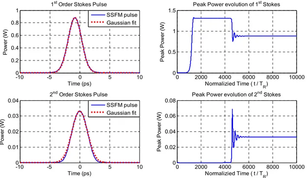
The main objective of the analysis is to determine if the output Stokes pulses converge to dispersion managed solitons at steady state. Split Step Fourier Method (SSFM) is being used to solve the coupled NLS equations. The 1st and 2nd order
Stokes signals are obtained at the output for different pump power and SMF length (determines the net anomalous dispersion) combinations. In Figure 2, the output Stokes pulses and their peak power evolution are shown as an example of transient analysis. The envelope of the output Stokes pulses is also characterized by comparing with a Gaussian pulse with the same pulse parameters.
Figure 2. The output Stokes pulses (2a) with Gaussian fitting and the evolution of their peak powers (2b) at LSMF=50m and
Ppump=0.72W. TRT is the round trip time of the cavity.
The intra cavity pulse dynamics of the Stokes pulses are also investigated by extracting the evolution of pulse parameters through the single pass. Figure 3 illustrates the evolution of peak power and the pulse width (FWHM) of the Stokes pulses at steady state. The dynamics of the pulse parameters of the Stokes pulses has similar characteristics. Through the dispersion managed section of the cavity where all the Raman interactions occur, the gain and the nonlinear effects such as single phase modulation (SPM) and the cross phase modulation (XPM) are the dominant terms. Thus, the Stokes pulse are amplified and positively chirped though the dispersion managed (DM) fibers. Because the dispersion length
(LD=T02/|β2|) through the individual highly nonlinear fibers (HNLF) is much more than the amplification
(LA= (gR|A|2)-1) and nonlinear lengths (LNL= (γ|A|2)-1) and due to net zero dispersion of the DM system, linear dispersive
effects become negligible as seen by the pulse width. However, in the second section of the cavity (standard SMF), since the pulses become separate due the walk off, there is no pulse to pulse interaction. The group velocity dispersion (GVD) is the dominant effect though the SMF. Since the pulses becomes highly positively chirped in the DM section of the cavity due to nonlinear phase, the Stokes pulses first compress and then broaden as seen by the dynamic of peak power and pulse width.
-10 -5 0 5 10 0 0.2 0.4 0.6 0.8 1 Time (ps) P ow e r (W )
1st Order Stokes Pulse
-10 -5 0 5 10 0 0.01 0.02 0.03 0.04 Time (ps) P o w er (W )
2nd Order Stokes Pulse
0 2000 4000 6000 8000 10000 0 0.5 1 1.5 Normalizied Time ( t / T R) Pe a k P o we r ( W )
Peak Power evolution of 1st Stokes
0 2000 4000 6000 8000 10000 0 0.02 0.04 0.06 0.08 Normalizied Time ( t / T R) P e ak P ow e r (W )
Peak Power evolution of 2nd Stokes
SSFM pulse Gaussian fit
SSFM pulse Gaussian fit
Figure 3. The intra-cavity dynamics of the steady state pulse parameters, peak power and pulse width of 1st order Stokes (3a) and 2nd
order Stokes (3b) at LSMF=50m and Ppump=0.72W are shown. The analytical and simulation results are compared.
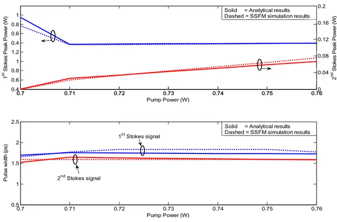
Figure 4. Steady state peak power (4a) and pulse width (4b) of the Stokes pulses with respect to pump power are shown. The
correctness of analytical derivations is also illustrated in the figure by comparing with the simulation results.
0 20 40 60 80 100 0 0.5 1 Propagation dstance (m) 1 st St o ke s Pe a k Po w e r ( W ) 0 20 40 60 80 100 0 0.02 0.04 0.06 Propagation dstance (m) 1 st S to kes P u ls e w idt h ( p s) 0 20 40 60 80 100 0 0.5 1 1.5 2 Propagation dstance (m) 2 nd S tok es P e ak P o w e r ( W ) 0 20 40 60 80 100 0 0.5 1 1.5 2 Propagation dstance (m) 2 nd S tok e s P u ls e w idt h ( p s) SSFM simulation Analytical SSFM simulation Analytical SSFM simulation Analytical SSFM simulation Analytical 0.7 0.71 0.72 0.73 0.74 0.75 0.76 0.4 0.6 0.8 1 1.2 0.4 0.6 0.8 1 1 st St o ke s Pe ak Po we r ( W ) 0.7 0.71 0.72 0.73 0.74 0.75 0.760 0.04 0.08 0.12 0.16 0.2 Pump Power (W) 2 nd S tok es Pea k P o w e r (W ) 0.7 0.71 0.72 0.73 0.74 0.75 0.76 0.5 1 1.5 2 2.5 Pump Power (W) P u ls e w id th (ps)
Solid = Analytical results Dashed = SSFM simulation results
Solid = Analytical results Dashed = SSFM simulation results
2nd Stokes signal
Analytically derived pulse parameters such as peak power and pulse width of the 1st and the 2nd order Stokes at
steady state with respect to different pump powers are also illustrated in Figure 4 with numerical results. The intra cavity dynamics of these parameters are analyzed by assuming the steady state values found by solving the differential equations at any point inside the cavity as the initial condition and integrating the equations for one round trip [9]. The analytical and numerical results are shown Figure 3 for specific SMF length and pump power (LSMF=50m and
Ppump=0.72W). The agreement with the numerical results obtained by SSFM verifies the validity of our variational
analysis.
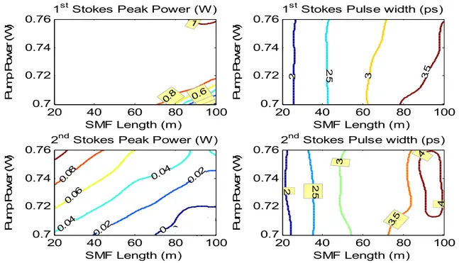
To investigate the stable regime of the output Stokes pulses, system is deeply analyzed by changing both the length of the SMF from 20m to 100m and for each case tuning the pump peak from 0.7W to 0.76W. The results are shown in the following contour plots indicating the peak power and pulse widths of 1st and 2nd order Stokes pulses.
Figure 5. Contour plots for the peak power and pulse width of the 1st and 2nd order Stokes pulses due to the SMF length and pump power.
Figure 5 illustrates the peak powers and pulse widths at which the output Stokes pulses converge at steady state. At low pump powers which are very close to threshold only the 1st order Stokes can be generated. When the pump power is
increased, 1st order Stokes signal starts to build up in the system and converge. If the final peak power of the 1st Stokes
signal reaches the threshold for 2nd Stokes signal, it generates the 2nd Stokes pulse. At high pump powers due to
imbalance between strong nonlinearity and weak dispersion, 1st Stokes signal starts to break up and system becomes
unstable. The robustness to nonlinearity increases proportionally with net dispersion. 4. CONCLUSION
We investigated the stability of dispersion managed synchronous Raman laser up to second order both analytically and numerically. The variational analysis is conducted to derive the differential equations which explain the intra cavity dynamics of Stokes pulses in terms of their pulse parameters. The coupled differential equations with a periodic boundary conditions are solved to obtain the output Stokes pulse parameters at steady state. The analytically and numerically derived pulse parameters of the Stokes pulses are compared to illustrate the correctness of the analytical analysis. The results show that the stable 2nd order Raman Stokes pulses with 0.04W to 0.1W peak power and 2ps to
0 0.2 0.4 0.6 0.8 1
1st Stokes Peak Power (W)
SMF Length (m) Pu m p Po w er ( W ) 20 40 60 80 100 0.7 0.72 0.74 0.76 2 2. 5 3 3.5
1st Stokes Pulse width (ps)
SMF Length (m) Pu m p Po w er ( W ) 20 40 60 80 100 0.7 0.72 0.74 0.76 2 2.5 3 3.5 4 4
2nd Stokes Pulse width (ps)
SMF Length (m) Pu m p Po we r ( W ) 20 40 60 80 100 0.7 0.72 0.74 0.76 0 0 0 0.02 0.02 0.04 0.04 0.06 0.08
2nd Stokes Peak Power (W)
SMF Length (m) Pu m p Po we r ( W ) 20 40 60 80 100 0.7 0.72 0.74 0.76
3.5ps pulse width can be achieved in DM system. Results can be further improved by optimizing the parameters of the dispersion management.
5. ACKNOWLEDGEMENT
This work is supported by DARPA RADER Program and EU grant PIRG07-GA-2010-268370. 6. REFERENCES
[1] C.J.S. Matos, S.V. Popov, and J.R. Taylor, “Short-pulse, all-fiber, Raman laser with dispersion compensation in a holey fiber” Opt. Lett. Vol. 28, No. 20 (2003).
[2] G H. Renner, S. Cierullies, M. Krause, “Scaling rules for Raman fiber lasers” OFC, Atlanta, USA (Paper MF25), (2003).
[3] M. Krause, H. Renner, “Theory and design of double-cavity Raman fiber lasers” J. Lightwave Technology, Vol. 23, No. 8 (2005).
[4] S. Cierullies, H. Renner, E. Brinkmeyer, “Numerical optimization of multi-wavelength and cascaded Raman fiber lasers” Opt. Commun. 217(1-6), pp. 233-238 (2003).
[5] G.P. Agrawal, [Nonlinear Fiber Optics 4th edition], Academic Press (2009).
[6] OFS Specialty Photonics Division, http://ofscatalog.specialtyphotonics.com
[7] H.A. Haus and M. Nakazawa, “Theory of the fiber Raman soliton laser”, J. Opt. Soc. Am. B/Vol. 4, No.5, (May/1987).
[8] A. Hook, D. Anderson, and M. Lisak, “Effects of cross-phase modulation and pump depletion on Stokes pulse dynamics in stimulated Raman scattering”, J. Opt. Soc. Am. B, Vol. 6, No.10, (Oct/1989).
[9] Cristian Antonelli, Jeff Chen, Franz XKartner, “Intracavity pulse dynamics and stability for passively mode-locked lasers”, Optics Express, Vol. 15, No.10, (May/2007).