SUMMARY
INDEX CONTENTS
Chapter 1: M&S Fundamentals
1. 1 Modeling & Simulation basic concepts ... .1
1.2 Development phases in a simulation model ... .2
1.3 Simulation Models Classification ... .4
1.4 Interactive simulators ... .5
1.5 5 Architectures for distributed simulation: The High Level Architecture (HLA) and its evolution ... .5
Chapter 2: Modeling and Simulation For Training In Marine Ports: Approaches, Methodologies, Best Practices Criticalities and Requirements 2.1 Introduction ... .7
2.2 Acronyms List ... .8
2.3 Modeling & Simulation for training in Logistics ... .8
2.4 An example of simulation based training: driving simulators ... 10
2.5 An overview on software tools ... 11
2.6 Modeling and Simulation in marine ports and harbor terminals ... 19
2.7 Training Needs in the last mile of navigation ... 21
References ... ...23
Chapter 3: Architecture Design and HLA view 3.1 Introduction ... 26
3.2. The “Training & Exercise” system: goals and scope... 26
3.2.1 The Ship Bridge Simulator ... 26
3.2.2 The Control Tower Simulator ... 27
3.2.3 The Tugboat Bridge Simulator ... 28
3.3 Architectural design of the Simulators Federation ... 28
3.3.1 Ship Pilot Training Operator Simulator Requirements ... 30
3.3.2 The Control Tower Operator Training Simulator ... 31
3.3.3 The Supervision system ... 31
3.4 Design of the Federation Architecture – HLA view ... 32
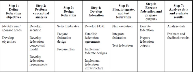
3.4.1 Federation Development and Execution process (FEDEP) ... 35
References ... ...38
Chapter 4: Ship and Control Tower Simulators Development & Integration 4.1 Introduction ... 39
4.2 The sea-keeping problem: the ship motion equations ... 40
4.2.1 The surge, sway and yaw equations ... 41
4.2.2 Roll, Pitch and Heave Equations ... 43
4.4 3D geometric models and virtual environments for the Ship Bridge Simulator……...47
4.5 The Control Tower Simulator ... ...51
4.6 HLA Integration for cooperative training ... ...51
4.6.1 The Federates and the Federation Object Model ... ….52
4.6.2 The Federation Object Model and the Simulation Object Models ... ….52
4.6.3 Federates performance measures definition ... ….59
4.7 Training Scenarios Definition ... ...59
4.8 Conclusions ... ...60
References ... ...61
Chapter 5: Hardware Integration and simulation system full prototype 5.1 The Ship Bridge Replica Design ... ……63
5.2 The Visualization System for the Virtual Environments, the Sound System and PCs requirements ... ……67
5.3 The Control Tower Simulator Workstation ... ……69
5.4 Rudder and Controllers Integration ... ……70
5.4.1 ADC………...71
5.4.2 Timer Interrupts………...71
5.4.3 Discrete Kalman Filter………..……71
5.5 The overall prototype system ... …….73
5.6 Conclusion ….. ... …….74
References ... …….74
Chapter 6: Other Related research activities: Simulation for Training in Car Terminals 6.1 Introduction ... …….76
6.2 Related Works ... …….77
6.3 Main Processes and Activities in a Car Terminal ... …….79
6.4 CTSIM General Architecture ... …….80
6.5 Performance Measures Description ... …….83
6.6 The Vehicle Simulator ... …….83
6.7 The Operator Simulator ... …….86
6.8 Conclusions………..87
References ... …….88
LIST OF FIGURES Chapter 2 Figure. 2.1 – 3D view of the Gioia Tauro Container Terminal (source: Bruzzone et al. 2011-b)…....20
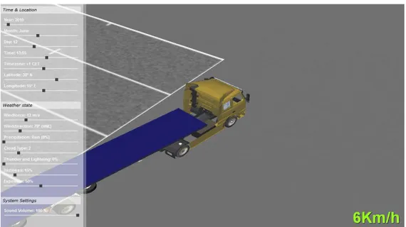
Figure 2.2 – Truck simulator within the Gioia Tauro container terminal (source: Bruzzone et al. 2011-b)……….20
Figure 2.3 – Crane simulator solutions developed by Simulation Team (Source. Bruzzone and Longo, 2008)………...21
Figure 3.1: Overall Architecture………...29
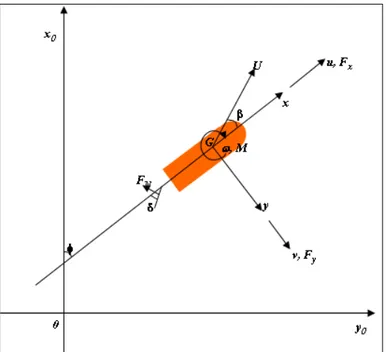
Figure 3.2: Ship Motion at sea reference systems, main forces and moments………...30
Figure 3.3: HLA Federation Architecture (a general overview)………....32
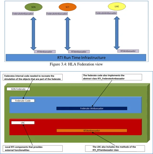
Figure 3.4: HLA Federation view………...33
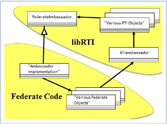
Figure 3.5: HLA Federate Architecture view ………....33
Figure 3.6: Code Responsibilities within the HLA Federate………..34
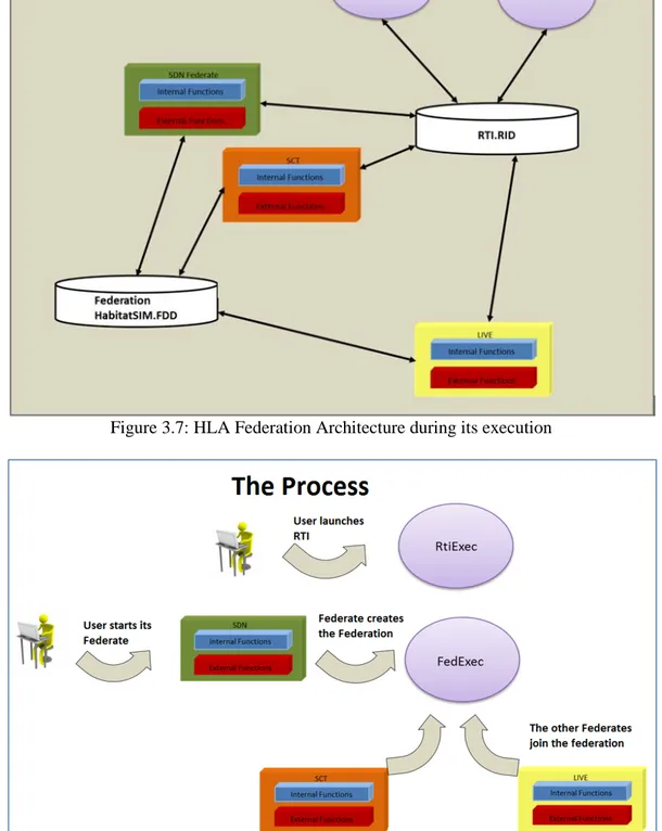
Figure 3.7: HLA Federation Architecture during its execution………..35
Figure 3.8: Federation Execution Process ……….35
Figure 3.9 – Federation Execution Process (source: IEEE HLA 1516.3 Standard)………...37
Chapter 4 Figure 4.1 – Reference system for ship motion equations (MMG, 1985)………..41
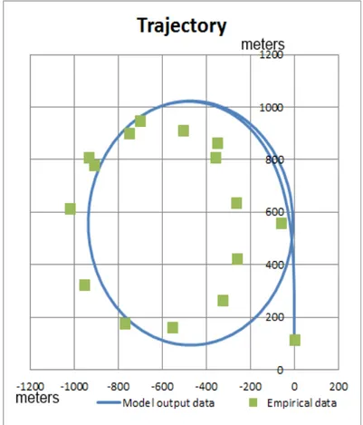
Figure 4.2: Turning trajectory in port side circle test, speed 8kn, rudder angle 35°………...45
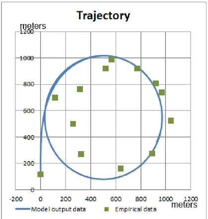
Figure 4.3: Turning trajectory in starboard side circle test, speed 10kn, rudder angle 35°………46
Figure 4.4: Turning trajectory in port side 20/20 zigzag test, speed 5kn………...46
Figure 4.5: Turning trajectory in starboard side 10/10 zigzag test, speed 5kn………...47
Figure 4.6 - Panoramic view of Salerno port………..48
Figure 4.7 – 3D geometric model of the Port of Salerno………48
Figure 4.8 – Detailed view of the 3D geometric model of the Port of Salerno………… …………...49
Figure 4.9: View on the Containership in the Virtual Environment of the Port of Salerno…………..49
Figure 4.10: Panoramic view of the Virtual Environment of the Port of Salerno………..49
Figure 4.11: View from the containership bridge………..50
Figure 4.12: Front view of the commercial containership……….50
Figure 4.13: The commercial containership back view (pitch, roll and heave motions)………..51
Figure 4.14: Training Scenarios Definition………60
Chapter 5 Figure 5.1: Prospective view of the ship bridge replica CAD………..63
Figure 5.2: Top view and dimensions of the ship bridge replica CAD………64
Figure 5.3: Front view of the ship bridge replica CAD………64
Figure 5.4: Left view of ship bridge replica CAD………65
Figure 5.5: Ship bridge detail: double lever system and multiple LEDs displays………66
Figure 5.6: Ship bridge detail: double lever system, joysticks for side thruster control, wheels for rudder control, multiple LEDs displays and small-size displays………...67
Figure 5.7: Ship bridge detail: navigation instruments and visualization area including AIS simulator, Conning display simulator, Radar simulator………..67
Figure 5.8: Prospective and top view of the foot for screen support CAD ………68
Figure 5.9: Prospective and top view of the CAD of the structure for projectors………..68
Figure 5.10: View of the projectors installed on the structure……….69
Figure 5.11 – The Control Tower Simulator……….70
Figure 5.12: The ship bridge replica and the visualization area………...73
Figure 5.13 – The ship bridge simulator and the control tower simulator working together for cooperative training of ship pilots and port traffic controller (Interoperability use mode and distributed simulation through High Level Architecture)………..74
Chapter 6
Figure 6.1 : Cars accident during loading/unloading operations in a car terminal………77
Figure 6.2: General architecture of CTSIM………...81
Figure 6.3: Cars parked in a Ro-Ro ship……….82
Figure 6.4: Avatar interacting with vehicles………...82
Figure 6.5 : Operator controls the avatar through a motion capture system……….83
Figure 6.6: Developing and testing the vehicle simulator at MSC-LES, University of Calabria………...85
Figure 6.7: Panoramic view of the car terminal………85
Figure 6. 8: Internal view from the car while approaching the ramp for entering the ship…...86
Figure 6.9: Vehicle simulator – inside view after a collision………...86
Figure 6.10: Operator Simulator, example of hand gestures………87
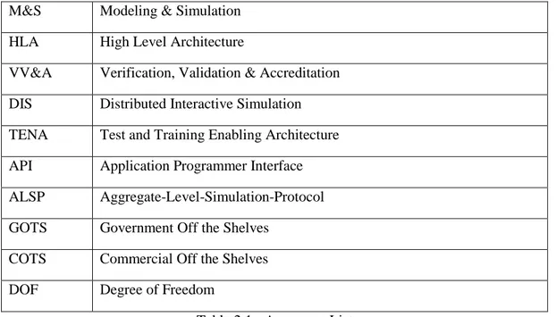
LISTS OF TABLES Chapter 2 Table 2.1 - Acronyms List……….8
Table 2.2 – Licenses comparison for different graphic engines………..13
Table 2.3 – Functionalities comparison for different graphic engines………...13
Table 2.4 – Licenses comparison for different software for 3D modelling………...14
Table 2.5 – Functionalities comparison for different software for 3D Modelling………..15
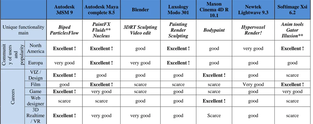
Table 2.6 – Community and Application areas comparison for different software for 3D modeling……….16
Chapter 3 Table 3.1 – Main software/ hardware modules………...28
Table 3.2 Tabular view of the main FEDEP steps (source: IEEE 1516.3 standard)………..28
Chapter 4 Table 4.1: Federation Object Model: the Object Class Structure Table reporting the list of all the object classes that are part of the federation………...53
Table 4.2: List of attributes for the SDN and STC federates……….55
Table 4.3: List of interactions and parameters for the SDN and STC federates…………...58
CHAPTER 1:
Modeling & Simulation Foundamentals
1.1 Modeling & Simulation basic concepts
Acting on a real system is the only way to know how it reacts when specific actions are undertaken but unfortunately, this approach is not always possible or convenient. Therefore, most of the time a physical or abstract model of the system under investigation is developed and trials and experiments are carried out on it. To this end, both physical and abstract models can be considered as a simulation of a particular system. Think of, for instance, the scale model of a ship that is used for model tests with the aim of estimating its hydrodynamic coefficients ant its performances parameters. This approach is usually preferred to traditional methods, based on physical laws that may be too difficult to deal with or to implement. On the other end, it is highly unfeasible, owing to the large amount of financial resources it requires, to build a real ship for sea trials. For this reason, resorting to a model can often be a useful approach when direct trials on a real system/object are unfeasible. However, it should be noted that an abstract model may entail two options:
• The model is simple and can be solved by an analytical /numerical or statistical approach, for instance:
o Differential equations; o Linear programming theory; o Queuing theory;
• The model is complex (like it really happens in practice) and if it is not possible to detect the mathematical laws governing its behavior and the stochastic component cannot be neglected then simulation is applied.
Simulation allows recreating a real system behavior through an artificial system that is a computational model. The process that leads to a computational model is in two stages. During the first stage, that is well-known as modeling, the system components, operating principles and functional relations are detected. Afterwards, a computational model (that can be either algebraic or algorithmic) for each component is developed based on the functional requirements previously detected. During the second stage, that is simulation, all the computational models run jointly and, the behavior resulting from their mutual interactions should be as close as possible to that of the real system. The comparison between the model and the real system is very important in both phases. During the modeling phase, the comparison involves each component and aims at adjusting the parameters they depend on to make the overall model recreating with accuracy the real system behavior. Therefore, correctness should be evaluated under two different perspectives:
- The correctness of the overall model (black box validity): the model outputs are very similar to the real system ones;
- Correctness of the single components (white box validity): each single component is consistent with reality.
Modeling is an abstraction process that entails many approximations based on assumptions whose validity has to be continuously called into question. Such approximations are related to the definition of the system main components (deciding to neglect the components that components having a secondary role respect to the phenomenon that is investigated), the identification of main working mechanisms and the related representation in terms of mathematical relations and algorithms.
The resulting model is valid only if the underlying hypothesis and assumptions are valid and in particular if all that is neglected is irrelevant. Indeed, a particular phenomenon can be deemed negligible depending on the purposes of the study. It means that the validity of a model should be evaluated within its own application and respect to the use it is meant for. Therefore, when the same model is going to be reused in another context the model validity should be checked prior to proceed. The main model components include:
- Variables
Simulation techniques may involve three different types of variables:
o State Variables: numerical and logical variables that include all the information needed at any time to describe the system with satisfactory accuracy. In other words, this category includes all the variables that are able to describe the system configuration while the system evolution during the simulation results from the dynamics of each of them. In addition, for
such variables, it is needed to specify the value they take before the simulation starts that is the system initial state or in other words the system initial conditions).
o Input Variables: such variables include the solicitations the system reacts to while the simulation executes.
o Output variables: such variables depend on state and input variables and are the quantities that are observed during the simulation like for instance system performances indicators.
- Events
An event is whatever occurrence that makes at least one state variable change. For instance, the user arrival in a queuing system o a service completion are examples of events. There may be:
o Events that are external to the system (exogenous events); o Internal Events (endogenous events);
For instance, processing a user in a queuing system is an endogenous event because it occurs inside the system while a new user arrival is an exogenous event.
- Entities and attributes
Entities are single elements of the system that have to be defined. For instance in a queuing system, user and servant are two different entities. In addition, considering the user entity, since it flows through the system, it is defined as a dynamic entity while the servant is a static entity. Entities may be characterized by attributes that provide the values of data the entity has been assigned to. For instance in a single servant queuing system where the only entities are the servant and the users an attribute of the user entity is user arrival time while the servant can hold the attribute status that may take the values “free” or “busy”. It is worth mentioning that attributes definition depend on the system under study as well as on the aims of the study. Furthermore, entities can be grouped into classes encompassing entities of the same type. Considering men and women the users of a queuing system, entities can be grouped into two classes based on the value taken by the attribute “sex”.
- Resources
Resources are elements of the system that provide services to the entities. An entity may call for one or more resources and in case of resource unavailability the entity may enter a queue waiting for the resource availability or take a different action. Otherwise if the resource is available, it can be accessed by the entity, retained for a while and then released.
For instance, a resource could be an operator that oversees a machine. In case of technical and economic constraints that prevent the machine from being used if the operator is not available, the resource availability has to be checked whenever an entity calls for the resource. After the availability check, if the resource is free, the request can be fulfilled and as a consequence the resource will be retained for a while and afterwards released. In case of unavailability, the entity has to wait until the resource is released. It is worth noticing also that a model component can be considered as a resource or as an entity depending on how the model has been built.
- Activities and delays
An activity is an operation whose duration is not known a priori when it starts. Such duration can be constant such a random value from a probability distribution or an input data, or a value that is calculated according to contingent events occurring within the system; for instance the service time in a queuing system. Conversely, a delay is a period of time with undefined duration that depends on the system conditions; for instance the time an entity spends in a queue before a resource is available.
1.2 Development phases in a simulation model
The step that are required to develop a simulation model are part of a methodological approach that includes a set of fundamental steps. It is not a simple sequence of stages but a rather iterative approach that may require reviewing and integrating activities when new knowledge on the system is available or when the expected results are not achieved. The development phases of a simulation model are illustrated as follows:
- Problem formulation: this is a preliminary phase where the main problem the model is devoted to investigate is defined thus the system under investigation and its boundaries are identified. This way, the main elements that have to be included in the model because of the relevance they have in
characterizing the system structure and its behavior are detected. In the same way, unnecessary elements that do not provide a meaningful contribution to the system characterization are neglected. For instance, if the purpose is to investigate an industrial process, the boundaries of the system have to be carefully identified and the attention should be put on the most important aspects only. It may result in focusing on a particular production line and on the machines that are part of it if a performances analysis is required or on the raw materials and finished products warehouse if the goal is to investigate inventory management policies.
- Setting the goals: it means that the objectives of the simulation study have to be set. At this stage, it is required to detect the questions the simulation study will answer as well as the expected results. To this end, it is worth noticing that simplifying assumptions directly depend on the objectives of the simulation study that have been set at this stage. The objectives can be:
o Performance analysis : with reference to resources, flow time, system outputs, etc; o Capability analysis: that means to verify if the resources are properly used;
o Comparison: that means comparing alternative configurations in order to detect the most suitable solution given a set of constraints;
o Optimization: find the best solution among a wide set of alternatives;
o Sensitivity analysis: understand which variables and to which extent they affect the system; o Visualization: develop a visual solution of an non-existent system.
Taking the example previously given, the aim of a production line study could be the need to find out an optimal set of technical parameters for each machine so as to maximize the line performances while the objective of a study focused on warehouse could be to detect the best inventory policy. At this stage, once the objectives of the study are clear, it is also required to evaluate the time and the resources are required to carry out the simulation project as well as the costs and the financial resources it entails.
- Conceptual Model Definition: in this stage it is required to decide the level of detail and abstraction of the model detecting its main entities, attributes, resources, functional requirements and structural complexity. As a matter of facts, well detailed models are difficult and expensive to develop, to correct and to maintain. On the other hand, a simple model a oversimplification or a high degree of abstraction, makes the model far from representing the real system. The level of detail, therefore, has to be evaluated under two perspectives: the complexity it brings in and the results accuracy it allows achieving. Indeed, it may happen that to complex models may bring about unreliable results while too simple models may result in too approximate outputs. Afterwards, rules and logical, mathematical, causal relations among the system structural components have to be detected so has to gain a detailed knowledge of how the system works. The aforementioned elements made up the conceptual model of the system that has to be simulated. To develop a conceptual model a “top-down” approach is usually adopted, it means that starting from simple elements the model is then refined until the desired complexity is reached. However, it is worth considering that as complexity increases as errors are more likely to occur and the simulation costs and times grow. Taking once again the production line example the main modeling elements include machines, work pieces and operators; interactions among this element result in processing operations while the rules that are needed to recreate a faithful operational picture of the system include operations scheduling criteria, priorities policies for processing different production orders, how exceptions are handled, machines maintenance policies, shifts, etc. A conceptual model may be not so useful when simple systems are simulated but is unavoidable for complex system simulation. Indeed, conceptual models that are often in the form of diagrams (such as UML diagrams, flow charts, etc.) should be the preliminary activity of each simulation study where a complex system is to be investigated. Moreover, conceptual models are qualitative in nature and can be considered a fundament step toward the development of a dynamic simulation model. Therefore conceptual model are drawn before the system model is encoded so as to be processed by a computer.
- Data Collection: in this phase quantitative data and information on how the system works are collected. In other words, data on operating parameters, layout, operational procedures, and whatever input to the system are gathered. Particular attention should be paid on stochastic data for which the statistical distribution they belong to has to be identified so as to correctly represent such data within the simulation model. When the probability function cannot be supposed a priori, historical data should be retrieved and the best fitting distribution has to be detected. For instance, if a production system is under investigation, data collection may involve operating times and failure rates that are
random variables whose statistical distributions have to be identified. Data can be available in an electronic format and organized in a database.
- Model Encoding: the conceptual model previously drawn up and enhanced further to data collection, is encoded in order to be processed by a computer. In other words an executable program is developed. It may happen through an ad hoc programming code or through simulation software that automates the encoding phase thanks to the availability ready to use objects and applications. The major criticalities at this stage pertain to the encoding tool/ programming code selection for a proper translation of the conceptual models previously expressed.
- Verification: it pertains to faults detection further to the encoding phase. As a matter of facts the executable program should implement the conceptual model without any syntactic or semantic error. - Validation: it aims at testing the simulation model reliability. Among the possibilities available for model validation, pilot simulations can be carried out to assess whether simulation results are compliant with the real system outcomes (it may happen also that a reference model is referred to instead of the real system) and if such results are not in agreement either the model or the collected data have to be adjusted.
- Design of experiments: this phase consists of an experimental plan including different simulation scenarios. Experiments may be carried out by using the simulation model with two different approaches: an iterative and a comparative approach. The former implies that the model is running and its outputs are observed. In other words, it comes to implement an action and see how the model reacts. The latter, instead, means that one or more critical parameters are changed once or more than once and the model outputs are compared. This analysis allows investigating the influence of such parameters so as to detect the best solution in terms of system operating conditions. In such a case, the experimental plan is made up of several experiments where different system configurations in terms of control parameters and external conditions are considered. Furthermore, the number of replications of each experiment, the simulation run length as well as the rump up period (that is the system transition time before a steady state is reached) are to be established.
- Experiments execution: execution of the experiments according to the experimental plan.
- Results analysis. In this phase the output values for each system configuration are to be evaluated. Thus the results are processed using statistic techniques to build the confidence intervals of the system performances. Moreover, techniques for sensitivity analysis (such as Analysis of Variance, ANOVA) can be successfully used to detect the main factors affecting output data and therefore require particular care during the modeling phase.
- Presentation of the results. The simulator, the underlying assumptions and the results have to be documented as a final stage of a simulation study. Results and analysis are organized in tables, diagrams, and a useful mean for communicating with stakeholders that are not familiar with M&S concepts. Furthermore, verification and validation have to be validated as well to promote the simulator trustiness and make people confident of the simulation outputs reliability. Thus as a further step, if results are deemed valid can be used for reconfiguring and optimizing the real system.
1.3 Simulation Models Classification
A rather general classification of the simulation models can be done based on the main features of the system representation and on the experiments that are carried out:
- Static or dynamic simulation: static simulation analyzes the system in a particular point in time and does not consider how it evolves over time while conversely dynamic simulation allows monitoring the system states as time goes by.
- Deterministic or stochastic simulation: deterministic simulation does not consider uncertainties that may affect the real system while stochastic simulation does include random variates.
- Discrete or continuous simulation: dynamic simulation can be further classified into continuous and discrete simulation based on time management along the simulation. Discrete simulation means that time changes in a discontinuous way because simulation results are evaluated over a well established set of points in time and therefore all that happens between two subsequent points in time is neglected. On the other hand, continuous simulation means that time evolves on a continuous base. Choosing between a continuous or discrete model does not necessarily depend on the system features but can be mainly related to the purposes of the study. Indeed, a discrete model can be used as a representation of a continuous system. A typical example is a railway line where the train
position can be represented as a real variable that defines the distance from the departure station or , instead, with a set of binary variables that define the state of each block the line is made of.
1.4 Interactive simulators
Flexibility and dynamism are unavoidable requirements of modern economical systems. It implies that operators, especially those operators that are in charge of specific means such as plains, trains, ships, straddle carriers, quay cranes, etc., are required to fulfill their tasks effectively. In such a context, owing to practical, economical and security reasons training on the real system and with real equipment may be unfeasible. To this end, there are simulation based systems that allow training in a tridimensional virtual and immersive environment. Thus, operators can exercise and acquire the abilities required to do their job without endangering their safety and those of the operators sharing the same working environment and without any risk of economic damage. In this perspective, simulation based training results in an effective tool with lower costs compared to traditional training approaches.
1.5 Architectures for distributed simulation: The High Level Architecture (HLA) and its evolution The HLA has evolved over the past decade; in terms of architecture it has been equipped with a Run Time Infrastructure (RTI) that is a software devoted to manage communications among different models so as to address the simulators toward interoperability concepts without caring the issues pertaining to communication protocols. The RTI has been distributed by the DMSO (Defense Modelling & Simulation Office) since 2004 free of charge upon registration to the DMSO website. The relevance of such a tool has been widely highlighted by the NATO M&S Plan that has encouraged adopting this solution even if different European Nations part of the Alliance have put it in practice at different rates. As a result while simulation projects in the military domain carried out in North America are HLA compliant as a mandatory requirement of the DoD since 90’s, in other NATO countries the adoption of such a standard that has never been questioned has been delayed because of the background of the main private contractors. In response to this issue, over the period 1996-2000 the HLA Outreach Program was launched in USA. The main goal of the program was to educate and distribute, among Universities, knowledge pertaining to this standard in order to train students and provide them with the required skills and capabilities getting them ready to be employed in the main companies of the field. The U.S. Department of Defense entrusted the project to the McLeod Institute of Simulation Science (MISS) (where the and the MISS Italy - Genoa Center and the MISS Germany - Hamburg Center were particularly involved) and to the California State University Chico. In 2000 a similar initiative was activated: the SIREN (Simulation Report & Networking) for technology transfer in European companies. The project was led by the the McLeod Institute of Simulation Science and in particular from the Italian branch in cooperation with Liophant Simulation. As a result of the SIREN initiative, advanced training courses on HLA have been organized providing the audience with competencies certifications both at academic and professional level. In parallel to the initiatives in the military domain, further developments based on the integration of simulation models in a HLA cooperative environment took place in the industry sector (i.e. the IMS Integrated Manufacturing System initiative of the NIST, the WILD Web Integrated Manufacturing System project of DIPTEM , the E²M Project of the CIDISI from Argentine). In particular the first documented experience where a HLA federation distributed over a WAN/GAN network (a non-military network) has been carried out on December 6, 2000 from the DIPTEM of Genoa and the Riga Technical University. During the experiments, COTS non HLA- COMPLIANT simulation tools (i.e. Arena™, Simple++™, Simul8™) have been integrated into the HORUS (Hla Operative Relay Using Sockets)architecture aimed at developing a M&S methodology for Supply Chains through interacting simulators geographically distributed over a distance of 2100 Km. Further to such initiatives and with the support of other leading Institutions such as SISO (Simulation Interoperability Standards Organization's) e SCS (Society for Computer Simulation International) HLA became an international standard in 2000 (IEEE 1516 Standard for Modelling & Simulation). The standardization process has deeply encouraged the HLA adoption process to such an extent that the majority of distributed and interoperable simulations rely on the HLA standard.
In 2003 the HLA as a IEEE standard has undergone some modifications and new releases, where some relevant advances are absorbed into, are going to be issued. Indeed, since 2005 a revision process promoted by SISO has started with the aim of taking advantage from the latest development in different application domains (i.e.healthcare, logistics, etc) and in ICT technologies to ensure greater interoperability and reuse of simulation components. The main topics covered include IEEE 1516 - Standard for Modeling and Simulation (M&S) High Level Architecture (HLA) - Framework and Rules:
IEEE 1516.1 Standard for Modeling and Simulation (M&S) High Level Architecture (HLA) -Federate Interface Specification – devoted to define the interface among the federates (utilities, or interfaces with real systems) highlighting the software services that are needed to ensure the mutual support of federates in a distributed environment.
- IEEE 1516.2 - Standard for Modeling and Simulation (M&S) High Level Architecture (HLA) - Object Model Template (OMT) Specification – where storage formats and syntax for objects data and HLA models information are defined. Thus, it is possible to detect data exchange at runtime. Among the main befits, technical solutions for Distributed Simulation Environments (DSEs) obtained through a phased approach cannot be neglected. As a matter of facts even if the standard is focused on scalability, maintainability and bandwidth, the RTI interface needs to be improved to allow for a better scalability and a more flexible Data Distribution Management as far as data filtering for the different federates. In addition, Object models, in the latest versions, have been extended using XML AND Unicode to take advantage of new opportunities. Furthermore it is worth introducing an interesting initiative called XMSF (Extensible Modeling and Simulation Framework) has been carried out by a set of research centers (i.e. SAIC, MISS, VMASC, MOVES, George Mason University, Naval Postgraduate Monterey, etc.). The basic concept under the XMSF is the combined use of a set of different standards and best practices for web based M&S. The main idea is to use Markup languages based on XML as well as on web technologies and services for a new generation of distributed interoperable simulators.
CHAPTER 2:
Modeling & Simulation for Training in Marine Ports: Approaches, Methodologies, Best Practices Criticalities and Requirements
2.1 Introduction
This thesis was developed as part of the research project PON01_01936 – HABITAT, Harbor Traffic optimization System carried out in cooperation between the MSC-LES lab of the University of Calabria and some major Italian stakeholders working in the field of Logistics and Transportation.
As far as the objective of the Doctorate course is concerned, particular attention was paid to the development of a simulation based Training & Exercise system for pilots and port traffic controllers involved in the last mile of navigation. This simulation based Training & Exercise System is based on distributed simulation (the standard for distributed simulation used is the IEEE 1516 HLA, High Level Architecture) that enables both the training of individual operators and the cooperative training of more operators at the same time. Training of more operators (for example, a pilot of a vessel, a pilot of a tugboat and a port traffic controller) becomes possible because the different simulators are interoperable each other and they are therefore able to exchange information while sharing the same virtual environments (the latter are used to provide users with the sensation of being in the real system). As mentioned, the simulators interoperability requirements are guaranteed by the fact that the simulators architecture is built according to the standard for distributed simulation HLA.
The objective mentioned above been achieved through three specific activities, namely the development of the training & exercise system for pilots (we will refer to this activity also as the development of the Ship Bridge Simulator), the development of the training & exercise system for port operators (we will refer to this activity also as control tower simulator) and the development of the teleportation functionality for port traffic controller.
Therefore the different chapters of this thesis present the general architecture of the two simulators (the ship bridge simulator and the control tower simulator) and explain how different problems have been faced and solved. Among others, specific attention has been paid to interoperability issues explaining how (from an architectural point of view and from a development point of view) these issues have been solved. As far as the ship motion at sea is concerned, this can be regarded as the main modelling and analytic effort of the entire work; indeed a 6 Degree of Freedom (DOF) model for a containership motion at sea is proposed, coded, tested and validated. Concerning the training scenario, this is based on 3D virtual environments that recreate the Port of Salerno, Italy (this because the port of Salerno is involved as end-user of the project HABITAT). In addition, as part of this PhD work, a ship bridge replica has been designed and recreated including all the on board instrumentations used for ship navigation (e.g. Radar simulator, Conning Display system, AIS simulator). The ship bridge replica, that is part of the system, has been designed to be a faithful representation of a real ship bridge. To this end, at the early stage of the design process some real ships were surveyed. In particular, much time was spent on board of two ships: a platform supply vessel that was standing in the port of Crotone (Italy) and a container carrier that was entered into the port of Salerno. These visits were really useful to have a faithful representation of the ship bridge in terms of geometry and technical equipment for ship maneuverings and navigation. Concerning the control tower simulator, this allows the user monitoring and controlling the traffic within the harbor area by using different panoramic views on the virtual environments and by exchanging information with the vessels moving in the harbor area. The control tower simulator is also equipped with the Teleportation functionality; thanks to this functionality the port traffic controller can be virtually teleported on board the ship bridge and have the same view perceived by the ship pilot. This functionality provide the port traffic controller with a tremendous advantage for skills improvement and training effectiveness: he can see the traffic within the harbor area from the same point of view of all the pilots currently working on board the different ships within the harbor area.
As far as this chapter is concerned, it provides the reader with a detailed state of the art overview, pointing out how Modeling & Simulation based approaches have been used over the last 30 years to support training in different areas: from Industry to Logistics, from Defense to Homeland Security. The survey of the state of the art reveals that in the logistics area and, in particular, in marine domain, a lot of researches have been done to support training of operators working on the land-side (e.g. operators working in container terminals and car terminals, such as quay cranes operators, trucks drivers, straddle carrier operators, car drivers, etc.). Concerning the last mile of navigation, different solutions for ship pilots training are already available (ship bridge replica simulators); however, there is a lack of research on cooperative training of ship pilots, port traffic controllers and tugboat pilots (indeed the project HABITAT also includes a simulator for tugboat
pilots training). Therefore, the major innovative aspect of the work done during the PhD is the development of interoperable and distributed simulators that can be used to support cooperative training of multiple operators.
Before going into details, this chapter is organized as follows: in the first part an overview of Modeling & Simulation for training (with particular attention to Logistics) is given; then an overview on the most known used graphic engines and software for 3D models development is proposed. Finally training needs in harbour terminals are identified and discussed and a summary of the main processes, activities and actors involved in the last mile of navigation is given.
2.2 Acronyms List
The following table reports the list of acronyms used throughout this chapter and where needed also in the successive chapters of this thesis.
M&S Modeling & Simulation
HLA High Level Architecture
VV&A Verification, Validation & Accreditation
DIS Distributed Interactive Simulation
TENA Test and Training Enabling Architecture
API Application Programmer Interface
ALSP Aggregate-Level-Simulation-Protocol
GOTS Government Off the Shelves
COTS Commercial Off the Shelves
DOF Degree of Freedom
Table 2.1 - Acronyms List
2.3 Modeling & Simulation for training in Logistics
The purpose of logistics is to move objects and people while minimizing costs and respecting constraints on delivery times and service levels provided to final customers. Indeed, companies operating in the area of logistics and supply chain are nowadays required to readapt quickly and efficiently their structures, processes and activities to face continuous increases in freight volumes and significant changes in procedures and standards. Speed, ability, agility, resilience are only some of the properties required to a company for surviving in a global market and are the keys to success. In this scenario, training is the crucial element for all the people involved, from managers to operators and workers.
As far as training is concerned, it is not always possible to adopt the so-called training on the field; let’s consider as example the equipment used in a harbor terminal for containers handling. Inexpert operators may easily cause accidents with severe damages to goods as well as injuries to people and sometime even deaths. Regarding marine ports and harbor terminals, this is also true when the training of ship pilots and port traffic controllers is concerned. Ship pilots are required to control very large vessels and to executes very complex maneuvers in narrow spaces; wrong procedures as well as wrong maneuvers may cause congestion in port traffic, high security risks and, sometime, even terrible accidents (as happened in 2013 when the containership Jolly Nero was exiting the port of Genoa in Italy).
In such a context, Modeling & Simulation (M&S) has largely proved to be one of the most powerful methodologies for training of operators working in complex systems (such as ship pilots and port traffic controllers). Over the last 30 years, M&S based approaches have shown their potentials not only for training but also for decision support. Indeed, within harbor terminals, M&S can be used for different purposes including maximize the space for storage services in yard areas, schedule arrivals and berth assignment,
optimize routes, resources assignment and loads, test emergency procedures, schedule work plan of workers, etc.
Over the time, the advantages of M&S for training activities have become increasingly significant; as result, M&S has emerged as a powerful training tool. M&S based training system aims at improving trainees’ performances with virtual and synthetic environments. Such environments are created in order to teach competencies, attitudes, concepts, knowledge, rules and skills providing trainees with the opportunity to practice the required competencies and receive real-time feedbacks (Salas et al., 2008). Trainees may act in synthetic environments as they usually act in real systems (learning how to put into practice the theoretical concepts) and can easily see the consequences of their actions in a visual manner. The main benefits associated with simulation based training approaches rely also on the possibility to set-up and design training sessions that include all the possible working conditions (that cannot be easily recreated in a real system). Therefore, well trained operators are prepared for any risky situation since they are aware of a great variety of cases and know exactly the consequences and effects of their behaviors and actions. A synthetic environment is safe, there is no danger, therefore, trainees can explore possibilities and test the effects of different actions in a cost-effective way (it is evident that both direct and indirect costs can be reduced). Another important aspect is the possibility to collect data from each training session so that instructors can analyze trainees’ performances evolution over the time, providing feedbacks to improve lessons learned and eventually compare the performance of different trainees based on different key performance indicators. As before mentioned simulation based training has been successfully applied in the most important sectors from Defense to Industry, from Logistics to Healthcare. Considering the military sector an overview about military simulation based training systems can be found in Page and Smith (1998) and Smith (2010). Practical examples of research works in which simulation is used for training can still be found in Page and Smith (1998), Zeltzer et al. (1995) and many others (for instance, Zeltzer et al. (1995) present a simulator for the training of submarine officers operating on the deck).
The analysis of the literature about simulation-based training systems cannot neglect industrial applications. Examples can be found in Jiing-Yih et al. (1997), Tam et al. (1998), Cramer et al. (2000), Anon (2000). In the Industry sector, many are the examples of driving simulators such as cars, excavators, construction machines, buses etc. References can be found in Greenberg and Park (1994), Lee et al. (1998), Freund et al. (2001), Park et al. (2001) and many others. Also riding simulators (mostly for bicycles and motorcycles) are proposed, see Carraro et al. (1998), Ferrazzin et al. (1999) and Kwon et al. (2001). However, among the existing visual interactive simulators, the flight simulation is the most mature and representative application; as a matter of fact a tremendous amount of researches has been published in this area, see Melnyk (1999), Bernard and Menendez (2000), Chin-Teng et al. (2001).
Also in the Healthcare sector, simulation based training has been extensively used and it has been found out its efficacy for teaching of technical and non-technical skills, learning and improving on patients' outcomes. Simulation based training for healthcare is a wide research area in which many sub-areas can be detected, e.g. anesthesia, surgical operations, intensive care, laparoscopy, endoscopy etc. Examples of research works can be found in Gaba and DeAnda (1988), Suwa (1992), Swank and Jahr (1992), Lussi et al. (1999), Morris et al. (2006), Daenzer and Fritzsche (2008), Semeraro et al (2008), Yoshida et al (2009), Sun et al. (2010). For instance, Murray (2011) provides reviews about the use of simulation to reduce human error during the administration of anesthesia.
In most of the cases the development of simulators for training purposes is based on the paradigms of distributed simulation in order to allow the cooperative and concurrent training of multiple operators. The High Level Architecture (HLA) standard, developed by the Department of Defense in the United States, provides a concrete example of approach to distributed simulation. An overview of standards and architectures for distributed simulation can be found in Fujimoto (2003). In additions, hardware integration as part of the simulators architectures is needed to increase to the feeling of realism and make the training experience pervasive and engaging. For example, Kwon et al. (2001) propose an interactive bicycle simulator including a Stewart platform to generate 6 DOF motions, able to provide force feedback on pedals and equipped with a dedicated visualization system. Melnyk (1999) develops a flight simulator in which the realistic feeling of takeoff, landing and in-flight turbulence are provided using a Six Degree-of-Freedom (DOF) motion system.
It is now clear that Simulation and virtual reality are tools that help strengthen the effectiveness of training because they allow suppressing constraints and limitations that are typical of traditional training approaches while maximizing the transfer of skills and competencies. If we subdivide learning activities between cognitive and psychomotor, scientific studies show that the use of simulation and virtual reality facilitate
both types of learning. In the case of cognitive learning, simulation and virtual reality allow avoiding certain logical steps providing the trainees with the possibility to arrive instantly to the core of understanding. Considering learning as a mental process that aims at the acquisition of reality, simulation and virtual reality are framed in the form of learning by doing. Indeed, the latest technologies behind the development of virtual environments allow trainees manipulating objects and acting in an autonomous and creative environment; virtual environments are therefore considered as tools that can profoundly transform the mode of communication and improve the learning skills.
In addition, the use of virtual, interoperable and interactive simulation to support training and education has considerable growth during the last 30 years benefiting from the rapid advances in computer technologies that traditionally is the backbone in the use of these methodologies. Originally used to solve costly and risky stages of pilots training in aviation, today simulators are used to simulate various types of vehicles and handling equipment, for both Industry and Military applications, including cars, ships, helicopters, submarines and even spacecraft.
In this context, where the ability of operators involved in the control and command of complex equipment represents an element of critical importance for the correct use of the equipment itself and where the use of a real equipment in the initial stages of training it appears not possible (vehicle design phase), or expensive (huge costs related to the use of the equipment for training) or even dangerous for safety and security reasons, simulators based virtual environments must be regarded has the best available solution for training purposes. Two events in particular have favored the development of simulators for training:
1. the first one was the rapid growth of computers, which allowed the modeling and the digital control of complex systems and equipment starting from the equations governing their physics and dynamics;
2. the second one was the rapid development of digital graphics that allowed experiencing realistically what the operator sees and feel while operating the real system. Indeed trainees once immersed in virtual environments are subjected to the perception of visual and audio effects as well as movements, velocity and accelerations (e.g. by using motion platforms) that are quite similar to those perceived in the real system. The hardware integrated as part of the simulator (e.g. steering wheels, pedals, gear, joysticks, etc.) provide the virtual environments with all the inputs (given by trainees) needed to let the system itself evolve as the time goes by (e.g. in a driving simulator, pushing the acceleration pedal will result in an increase of speed of the simulated vehicle).
On the basis of these considerations, in this thesis M&S based training has been used to pursue:
• more standardization, quality, and effectiveness of training procedures of the operators involved in the last mile of maritime navigation through the simulations of critical operations and emergency procedures with the aim of training the staff involved to handle situations otherwise too dangerous to recreate in real systems;
• significant reduction in the cost of staff training through a substantial reduction of the working hours of expert operators that are not directly involved in training of inexperienced staff;
• reduction of direct and indirect costs attributable to the occurrence of accidents during training. 2.4 An example of simulation based training: driving simulators
The following section provides the reader with an example of the potentials of simulation based training considering the case of driving simulators. Driving simulators are mainly used for vehicles tests, personnel training and entertainment.
Indeed, even in the case of simple functional tests of vehicles, a simulator can introduce significant advantages: for example, in the automotive industry simulation is commonly used to improve quality in terms of performances, safety or cabin ergonomics, reducing at the same time development costs and the number of prototypes. Simulators combined with motion platforms are also used to recreate the forces acting on the vehicles during its use (and as consequence of the driver behavior) allow studying how the driver perceives the vehicle comfort and how the comfort can be improved (specific sensors are used to measure noise, shock absorber behavior as well as the reactions of the drivers and other people in the car).
Furthermore, an interesting application of driving simulators is the study of new security systems such as the Electronic Stability Control (ESC). The ESC system detects when a vehicle moves in a direction different from that indicated by the position of the steering wheel and automatically activates the brakes (controlled by a computer), on specific wheels in order to stabilize the vehicle and help the driver to avoid accidents. As example, consider the National Advanced Driving Simulator (NADS) that is a research center affiliated with the University of Iowa and with the Department of Transportation of the United States leading a
research project on this subject. This research started by a proposal of the Department of Transportation of the United States to introduce the ESC on vehicles weighing less than 4536 kg and designed to carry passengers. This research has involved more than 500 volunteers between 16 and 74 years of age and is focused on driver’s response to dangerous situations and on the corrective effects of the ESC. Volunteers are required to use an immersive driving simulator; the scenario includes multiple obstacles that suddenly appear on the road and the drivers are required to avoid obstacles. The results collected from the simulations show the different behavior between cars equipped with ESC system and those that do not have it, showing the benefits of ESC.
Driving simulators can be also used to study the impact of the human factor on the causes of accidents. An example is again given by the NADS. The NADS has indeed done research on the effects produced by alcohol, drugs, medicines and other distractions such as telephone conversations while driving a car. In addition, driver's eye movements are also monitored and analyzed during the simulation.
However, the most widely known use of driving simulator is to train staff and operator. If we include in this area also flight simulators we can easily assert that these are for sure the most advanced applications (both for pilots operating in the military sector and commercial airlines). Vice-versa if we consider the driving of ground vehicles, driving simulators can be profitably used in car terminals to train drivers to load and unload new cars and vehicles on board/from ro-ro vessels.
Driving simulators can be also classified according to their capability to generate inertial feedbacks that is the capability to let the driver perceiving movements, velocity and accelerations that are normally perceived while driving the real vehicle or equipment. This classification divides the simulators in:
• static simulators: this are simulators that do not generate inertial feedback. These simulators are usually equipped with the real replica of the cockpit even if there are no motion platforms used and therefore the trainee can feel the sensation to drive the real vehicle just because he is immersed in a virtual environment where also advanced audio systems are used. This category also includes those simulators equipped with vibrations systems provided that the feedback perceived by the trainee are much lower than feedbacks given by dynamic simulators (the latter usually equipped with motion platforms).
• Dynamic simulators: these simulators are usually equipped with 3 degree of freedom or 6 degree of freedom motion platforms and therefore they allow trainees to perceive inertial feedback due to movements, velocity and accelerations. Motion platforms are usually equipped with electric or hydraulic actuators and are controlled real-time by a computer that, according to specific programs, is able to simulate movements, velocity and accelerations of the real vehicle/system. It should be said that, while the use of motion platforms (or similar tools) tremendously increase the training effectiveness, there are many cases in which their use is not indispensable. This is the case, for instance, of simulators used for study the ergonomics of new vehicles cockpits; inertial feedbacks in this case are not essential for finding out optimal and effective ergonomics of the vehicle cockpit. In addition, when the feedbacks provided by the motion platform are not correctly recognized by the human brain this may cause as dizziness, vertigo, nausea and vomiting (cybersickness). This usually happens when the stimulus perceived by the eyes is misaligned with the one perceived by the ears that control the movement and the equilibrium of the body in the space.
2.5 An overview on software tools
This section presents an overview on the most important and known software tools currently used for the design and development of simulators using for training. This overview has been then used to select the software used to develop the bridge ship simulators and the control tower simulators that are the final goal of this thesis.
The first step was the identification of the graphic engine, therefore an analysis of the current available graphic engines has been carried out.
A graphics engine can be defined as a set of methods, functions and classes that are used to implement a graphical application. Some engines only provide purely graphic functionalities while others integrate additional functionalities. The core functionalities typically provided by a graphic engine includes a rendering engine ("renderer") for 2D and 3D graphics and a physics engine or collision detection, sound, scripting, animation, artificial intelligence, networking, and scene-graph. If a particular feature or functionality is not already built-in, then it is entrusted to the developer to add this functionality implementing them personally or by using other software/middleware.
Based on this definition, many libraries provided by different programming languages can be considered as graphics engines. Let us consider for instance Visual Basic, it can be considered as a simple graphics engine because it offers a simple interface to create buttons, menus and all those components that allow the user creating an application in Windows environment. To achieve something similar in C ++, the user is required developing classes needed to create and manage windows. At higher level, there are graphics engines like DirectX and OpenGL that offer an extensive list of components to render 3D graphics, sound and controls. It can be said that DirectX and OpenGL have dedicated packages ready to be used to create real time graphics applications.
Whereas the graphics engines are very diversified according to the level where they work and the functionalities they offer, we have tried to outline the differences between the most known graphic engines. Among the criteria adopted for the graphic engines classification, one of the most important was the possibility to use as programming language C++; indeed, while C++ is used for the development of graphical applications it is also widely used to real-time and interoperable simulation. Tables 2 and 3 report the comparison among the graphic engines considered as part of this overview. Among others, additional criteria include the cost of the license, the availability of support, the availability of a physics engine, the terrain, the path finding and the blending animation.
From tables 2 and 3 it is clear that the Unreal Development Kit is the most powerful in terms of functionalities and in terms of non-commercial licenses cost. This graphic engine presents, however, some drawbacks that have led to its exclusion:
• high difficulty of use due to the large number of built-in features; • very high costs for the commercial license;
• possible problems if rendering is performed by using low or medium level computer (indeed this engine is currently used for the development of the most recent video games).
For these reasons, as second instance, it has been considered the possibility of using an open source engine considering as main criteria the size of the community currently using the open source engine, the existing documentation and the level of use for research and development activities; to this end we have considered OSG (Open Scene Graph). As far as OSG is concerned, we have experienced a number of problems and issues including, among others, compatibility issues with other software currently used for distributed simulation and difficulties in installing the compiler and plug-ins required to support its functionalities. These aspects together with the need of having a graphic engine able to be easily integrated with standard for distributed and interoperable simulation (e.g. HLA, High Level Architecture) has driven the final choice toward Vega Prime by Presagis. Indeed, this graphic engine was prevalently born to support real-time simulation applications for training; therefore, it provides many of the features necessary for the development of simulators. In addition to the graphic engines, an overview on software for 3D models development was carried out. The results of these overviews are reported in the following tables.
Irrlicht Ogre OSG Unreal Development Kit
3dvia
Virtools Quest3d C4 Torque
3d Game
Studio Vega
Version . . . Power Academic Torque 3d
Team Commercial
(3 users)
.
Non-commercial
license Free free Free Free 189€ 2499€
250$ (per student min 4) 100$ (per developer) 59€ Possibility to negotiate according to the available budget commercial
license Free free Free
$ 2,500 + $ 99 for up-front + 25% of the rights to earnings exceeding $ 5,000 ? 2499€ 350$ until 5 programmers 1000$ per developer + 225$ Starting from 9000 €
Table 2.2 – licenses comparison for different graphic engines
Irrlicht Ogre OSG
Unreal Development
Kit
3dvia
Virtools Quest3d C4 Torque
3d Game
Studio Vega
Physic not integrated
ODE, Novodex and Tokamak Vortex physics (add-on)
NVIDIA PhysX Ipion
(add-on)
ODE- Newton
Game Dynamics
integrated integrated integrated Vortex
(add-on)
Support forum forum Forum forum 10 token per
year/forum forum forum forum
forum/with ticket
Email support
path finding X X X √ √ (add on) √ ? X √ √ decision
making X X X √ √ (add on) √ ? X √ √
fluid simulation X X X √ ? √ √ √ √ √ cloth simulation X X X √ ? √ √ X X X bump mapping X √ X √ √ √ √ ? √ X mip mapping X √ √ √ √ √ √ √ √ X water rendering √ √ X √ ? √ √ √ √ √ particle simulation √ √ √ √ √ √ √ √ √ √ animation blending √ √ √ √ √ √ √ √ √ X special input device ? ? ? ? ? X ? ? √ √ dynamic shadows √ X X √ ? ? √ ? √ √
Table 2.3 – Functionalities comparison for different graphic engines
Autodesk 3dSM 9 Autodesk Maya complete 8.5 Blender Luxology Modo 301 Maxon Cinema 4D R 10.1 Newtek Lightwave 9.3 Softimage Xsi 6.2 te ac hi ng li cen se
price 6 months free or 130€
6 months free
version standard Unlimited standard Standard Base-study Standard Advanced
Non-commercial
license about 5000€ 2.500 € free 745
€ 720 base (+ € 800 probable
plugin)
695 € 450 €
first market Viz-Games Games-Film Viz-Realtime Viz-Games Motion-Design VFX-Viz Animation-Games-Film Table 2.4 – licenses comparison for different software for 3D modelling
Autodesk 3dSM 9 Autodesk Maya complete 8.5 Blender Luxology Modo 301 Maxon Cinema 4D R 10.1 Newtek Lightwave 9.3 Softimage Xsi 6.2 platforms
export collada very good very good very good good ? No very good
language FR ING ING Many but the best
ING ING JAP
ING FR IT
SPA JAP ING JAP ING JAP
Distribution
commercially very good very good low low good very good good
Age of Technology old old old / renewed modern renewed old / renewed modern
learning time to be
Support of the company for individual users
low / good good community very good very good very good very good
Supports reactivities
for single users good good community very good Excellent very good low
interface CAD style, clean and efficient How Forge, flexible and powerful, but not
intuitive
not as standards - fast workflow, it
might be more intuitive
Excellent clean and
intuitive old enough
texts logical and clean
interface
Documentation good Excellent good very good
(many videos) very good Excellent very good
Rendering Inside, MentalRay
Inside,
MentalRay Inside Inside Inside Inside Mentalray
Quality Excellent Excellent good Excellent good Excellent Excellent
tools di animazione (IK, Char Rig, Bones, Controller,
Blending,...)
very good Excellent good scarce scarce good Excellent
UV tools (Unwrap,
Pelt...) very good Excellent Excellent Excellent Excellent good Excellent
Painting absent very good scarce Excellent Excellent absent very good
Modelling Excellent very good good very good very good Excellent Excellent
Modifiers Excellent very good good very good good good very good
Autodesk 3dSM 9 Autodesk Maya complete 8.5 Blender Luxology Modo 301 Maxon Cinema 4D R 10.1 Newtek Lightwave 9.3 Softimage Xsi 6.2 Unique functionality main Biped ParticlesFlow PaintFX Fluids** Nucleus 3DRT Sculpting Video edit Painting Render Sculpting Bodypaint Hypervoxel Render! Anim tools Gator Illusion** C om m uni t y of us er s and popul ar it y North
America Excellent ! Excellent ! good Excellent ! good very good Excellent !
Europa very good Excellent ! very good Excellent ! good good good
C
ar
ee
rs
VIZ /
Design Excellent ! good good good Excellent ! good scarce
Film good Excellent ! scarce scarce scarce Very good Excellent !
Game Excellent ! very good scarce good scarce good very good
Web
designer scarce scarce good good Excellent ! good scarce
3D Realtime
/ VR
Excellent ! very good very good good Scarce good scarce
![Georges Güntert, Momenti salienti nella narrativa italiana fra Otto e Novecento, Franco Cesati Editore, Firenze 2020: [recensione]](data:image/gif;base64,R0lGODlhAQABAIAAAP///wAAACH5BAEAAAAALAAAAAABAAEAAAICRAEAOw==)