_________________________________________________________________ ALMA MATER STUDIORUM - UNIVERSITÀ DI BOLOGNA
CAMPUS DI CESENA
SCUOLA DI INGEGNERIA E ARCHITETTURA
CORSO DI LAUREA MAGISTRALE IN INGEGNERIA BIOMEDICA
DEVELOPMENT AND MECHANICAL CHARACTERIZATION OF A BIOSTABLE NYLON 6.6 ELECTROSPUN NANOFIBROUS
MULTISCALE DEVICE
FOR TENDON AND LIGAMENT REPLACEMENT AND SIMULATION
(Sviluppo e caratterizzazione meccanica di un dispositivo elettrofilato multiscala biostabile nanofibroso in nylon 6.6 per la sostituzione e la simulazione di tendini e legamenti)
Tesi in
MECCANICA DEI TESSUTI BIOLOGICI
Relatore Presentata da
Prof. Ing. Luca Cristofolini
Carlo Gotti
Co-Relatore
Ing. Alberto Sensini
Sessione III
1
Contents
Contents ... 1
ABSTRACT ... 5
ABSTRACT (Italian version) ... 7
1: INTRODUCTION ... 9
1.1: Structural connective tissues: tendons and ligaments ... 9
1.1.1: Hierarchical structure of tendons and ligaments ... 10
1.1.2: Mechanical properties ... 13
1.2: Tendons and ligaments mechanisms of injury and common cases ... 20
1.3: State of the art of tendons and ligaments replacement... 22
1.3.1: Synthetic biostable materials and devices for tendon and ligament replacement ... 23
1.3.2: Tissue engineering with 3D scaffolds ... 28
1.4: The Electrospinning technique ... 29
1.4.1 The Operating principles ... 29
1.4.2 Working parameters ... 31
1.4.3 Electrospinning in tendon and ligament tissue replacement ... 34
1.5: Developments and applications: soft-robotics – an overview ... 35
1.5.1 Soft Robots: actuation modes and prototypes ... 35
1.5.2 Soft exoskeletons and prosthesis ... 39
1.6: In vitro tendon and ligament simulators ... 48
2
3: MATERIALS AND METHODS ... 53
3.1: Materials ... 53
3.2: Production of electrospun nylon 6.6 bundles and ring bundles... 54
3.3: Production of the multiscale nylon 6.6 device and sheath ... 57
3.4: Design of grips and modification of electrospinning machine ... 61
3.5: Morphological characterization: optical microscopy and scanning electron microscopy ... 66
3.6: Mechanical characterization of bundles, ring bundles and multiscale nylon 6.6 device ... 67
3.6.1 Mechanical characterization of single bundles ... 67
3.6.2 Mechanical characterization of ring bundles ... 69
3.6.3 Mechanical characterization of multiscale nylon 6.6 device ... 69
3.6.4 Data analysis ... 70
4: RESULTS ... 73
4.1: Morphological properties ... 73
4.1.1 Morphology of nanofibers and bundles ... 73
4.1.2 Morphology of multiscale nylon 6.6 device ... 75
4.2: Mechanical properties ... 77
4.2.1 Mechanical properties of single bundles ... 77
4.2.2 Mechanical properties of ring bundles ... 78
4.2.2 Mechanical properties of multiscale nylon 6.6 device ... 79
5: DISCUSSION ... 83
5.1: Morphological properties ... 83
3
5.3: Future directions ... 91
6: CONCLUSIONS ... 95
5
ABSTRACT
Ligaments and tendons injuries are a widespread clinical problem worldwide, that compromises joint stability and patients’ daily movements and quality of life. Furthermore, their treatments have a high cost on the public healthcare system. Besides many procedures investigated in the past decades, involving allograft, autograft and synthetic devices, these presented many unsolved drawbacks. In fact there are no implantable devices, both for tissue regeneration and replacement, able to accurately reproduce, from the morphological and the mechanical point of view, their complex hierarchical structure and biomechanical properties. Moreover, there are no devices nowadays that are able to simulate tendons and ligaments in vitro, neither for biomechanical tests of new devices or surgical techniques, and for the training of surgeons.
For these reasons, in this work, thanks to the electrospinning technique, an innovative biostable nanofibrous nylon 6.6 multiscale device was produced, investigated and tested, both from a morphological and mechanical point of view. Obtained nanofibers had a mean diameter of 257 ± 43 nm, the same order of magnitude of tendons and ligaments fibrils. From these nanofibers, ring-shaped continuous bundles were obtained, manually wrapping the nanofibrous mats. The mean diameter of these bundles was 0.48 ± 0.05 mm, in line with fascicles diameter of tendons and ligaments reported in literature. Ring bundles were then assembled in a multiscale device, by electrospinning a novel randomly oriented nylon 6.6 sheath along the group of bundles, thanks to a customized electrospinning device. This contributed to their packing and tightening, mimicking the role of the epitenon/epiligament sheath. The mechanical characterization was performed, using ad hoc custom-made grips, at a strain rate typical of tendon and ligament injuries. The ring bundles reported a mean ultimate stress of 63 ± 11 MPa, Young’s modulus of 808 ± 89 MPa and ultimate strain of 10 ± 1.2 %. These values are in the same order of magnitude of tendon and ligament fascicles. The multiscale nylon 6.6 device reported a mean ultimate load of 333 ± 11 N, Young’s modulus of 321 ± 81 MPa and ultimate strain of 9.0 ± 0.2 %. These values are in line with many biological structures, with comparable dimensions, like patellar tendon, anterior
6
longitudinal spine ligament, medial collateral ankle ligament and anterior/posterior cruciate ligaments. Considering the results obtained, the multiscale nylon 6.6 device is proposed as a possible novel implantable biostable device, a valid simulation tool, but also as a component for those soft robots, exoskeletons and orthoses, that need fibrous cable driven actuation, in order to simulate the physiological behaviour of human tendons and ligaments.
7
ABSTRACT (Italian Version)
Le lesioni a tendini e legamenti rappresentano una criticità clinica a livello mondiale in grado di compromettere la stabilità articolare e la qualità della vita dei pazienti. Inoltre, il trattamento medico di questi infortuni risulta molto oneroso per il sistema sanitario pubblico. Nonostante negli ultimi decenni più soluzioni siano state proposte, comprendenti allograft, autograft e dispositivi sintetici, questi presentano notevoli criticità irrisolte. Non vi sono infatti dispositivi impiantabili, sia per la rigenerazione che la sostituzione di questi tessuti, in grado di riprodurne accuratamente sia dal punto di vista morfologico che meccanico, la complessa struttura gerarchica e le proprietà biomeccaniche. Inoltre, non vi sono ad oggi dispositivi in grado di simulare in vitro tendini e legamenti, sia per quanto riguarda test biomeccanici di nuovi dispositivi o di tecniche chirurgiche, nonché per l’addestramento dei chirurghi stessi.
Per i suddetti motivi, in questo lavoro di tesi, grazie alla tecnica dell’elettrofilatura, è stato prodotto, analizzato e testato, sia dal punto di vista morfologico che meccanico, un nuovo dispositivo multiscala, biostabile, in nylon 6.6, composto da nanofibre. Le nanofibre ottenute hanno mostrato un diametro di 257 ± 43 nm, corrispondete allo stesso ordine di grandezza delle fibrille di tendini e legamenti. Da queste nanofibre sono poi stati ottenuti dei bundles continui a forma di anello, avvolgendo manualmente le membrane di nanofibre. Il diametro medio calcolato di questi bundles è risultato 0.48 ± 0.05 mm, valori in linea con il diametro medio dei fascicoli di tendini e legamenti riportati in letteratura. I bundles ad anello sono poi stati assemblati in un dispositivo multiscala, elettrofilandovi sopra una guaina di nanofibre di nylon 6.6 disposte in configurazione random. Per l’elettrofilatura della guaina è stato utilizzato un dispositivo modificato ad hoc. Questo procedimento ha contribuito all’impacchettamento e al restringimento del diametro del fascio di bundles, riproducendo il ruolo svolto in ambito biologico dalla guaina tendinea e legamentosa. È stata successivamente eseguita una caratterizzazione meccanica, utilizzando afferraggi ad hoc e una velocità di deformazione paragonabile a quella tipica degli infortuni di questi tessuti. I bundles ad anello hanno riportato una tensione a rottura di 63 ± 11 MPa, un modulo di Young di 808 ± 89 MPa e una
8
deformazione a rottura di 10 ± 1.2 %, valori che sono risultati nello stesso ordine di grandezza di quelli di fascicoli di tendini e legamenti. Il dispositivo multiscala in nylon 6.6 invece, ha riportato valori ti carico a rottura di 333 ± 11 N, un modulo di Young di 321 ± 81 MPa e una deformazione a rottura di 9.0 ± 0.2 %. Questi valori sono in linea con varie strutture biologiche di paragonabili dimensioni, quali il tendine patellare, il legamento spinale longitudinale anteriore, il legamento deltoideo e il legamento crociato, sia anteriore che posteriore. Alla luce dei risultati ottenuti, il dispositivo multiscala in nylon 6.6 viene proposto come un possibile dispositivo impiantabile biostabile, un valido strumento di simulazione, ma anche come componente per quei soft robot, esoscheletri e ortesi, che necessitano di una attuazione guidata da cavi fibrosi che simulino l’andamento fisiologico di tendini e legamenti umani.
9
1: INTRODUCTION
1.1: Structural Connective Tissues: Tendons and Ligaments
The connective tissue provides structural and metabolic support to animal tissue1. It originates from the mesenchymal cells which are pluripotential and capable of generating different kinds of connective cells: osteoblasts, chondroblasts, adipocytes, macrophages, lymphocytes, mastocytes and fibroblasts2. Besides the cellular part, the distinctive feature of connective tissue is its abundant extracellular matrix3. It is interposed between cells and can be divided by its ratio of ground substance to fibrous tissue4. In this classification, tendons and ligaments are composed of dense, regular connective tissue. It is mainly characterized by collagen fibers, usually oriented in the same direction of the load which they have to support, and a low count of cells, almost fibroblasts5.
The principal function of tendons is to transfer the contraction force between a skeletal muscle and a bone. In this way, the muscle does not have to be directly connected to the bone, making joint movements and upright posture possible6. When the skeletal muscle is activated, it shortens itself. If it is connecting the two sides of a skeletal joints, this contraction will lead to the reduction of the joint angle, narrowing the two bones7. The tendon permits the detaching of the muscle from the bone, this frees up space at the joint insertion allowing the flexion of the forearm that otherwise would be impaired by the presence of the bigger muscle7. The tendon is connected to the muscle through the myotendinous junction and, when pulled by the muscle, it exhibits a high resistance with low strain, transferring the load to the bone via the osteotendinous junction8. Tendons do not only transfer forces in a linear way, their fibrous configuration makes them flexible and so capable of bending around the bones5. These contact zones act like pulleys and are also made of osteo-fibrous tissue1. For example, several tendons from the superficial flexor muscle of the fingers link the forearm to the fingers themselves passing through the carpal tunnel9. Healthy tendons exhibit a brilliant white colour due to the low presence of the cellular part and therefore of the vascularization1,10. Their length and width vary considerably with their function: the ones associated with big and
10
powerful muscles, are usually short and wide compared to the dedicated to precise movements ones. They also vary between individuals and even the same tendon varies significantly with age11. Their shape can range from wide and flat to cylindrical, fan-shaped and ribbon-shaped1.
Ligaments, like tendons, are made of connective tissue. Their function is to connect bone to bone providing mechanical stability limiting unwanted joint motions.6,8 Like tendons they are made of bundles of collagenous fibers. Ligaments can also prevent a joint from a forbidden movement6.
1.1.1: Hierarchical structure of tendons and ligaments
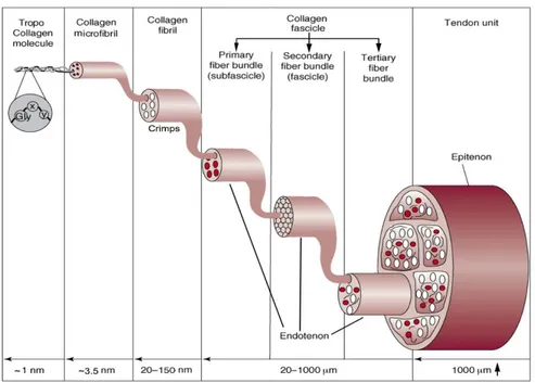
Tendons and ligaments structure is determined by their extracellular matrix, which is composed predominantly by collagen, proteoglycans and elastin, with the first one dominating in terms of composition1. The lowest structural level unit of tendons and ligaments is the tropo-collagen molecule; contrarily, there is no general consensus about the upper structural levels nomenclature and subdivision83 . This is probably due to the huge variability in this type of soft connective tissue and the limitations of the instruments used. In this work the hierarchical structure is referred primarily to the work of Kannus1, Goh8 and Kastelic3, all of whom show a certain accordance, and the description will follow a bottom-up approach.
• Tropo-collagen Molecules: this is the lowest structural level identified. This is, in fact, the most stable disposition in which the collagen aggregates. It is composed by three aminoacidic chains twisted together to form a triple-helix with a repeating sequence of three amino acids in the form “glycine – proline – X” or “glycine – X – hydroxyproline” where the X stands for a random other amino acid. The most common structure identified is type I collagen. These particular structure, permits to the collagen to be insoluble in physiological environment8.
• Microfibrils: A microfibril is a package of up to five tropo-collagen molecules intertwined with a right-handed twist. It has a diameter of about 3.5 nm and can be considered the basic structural unit of the collagen fibril.
11
• Fibrils: According to tomographic image investigations12, the cross-section of a fibril is usually made up of four microfibrils surrounded by a ring of ten microfibrils. The diameter of these ranges from 20 to 150 nm as reported by researchers1,8. These fibrils increase their diameter until the animal has grown and vary in different tendons and ligaments13.
• Fibers: Collagen fibers are usually assembled in bundles, in which the diameters of the fibers vary consistently in the same individual with anatomical site and in different species. Generally, can be identified in the order of magnitude of 100 μm7. The collagen concentration inside them is correlated with their diameter. Fibers are highly aligned inside bundles and their configuration is quite similar both in tendons and ligaments6. At this level the hierarchical structure is more evident but, despite this, the nomenclature is not unique. Accordingly to Kannus et al1, a bunch of collagen fibers forms a primary fiber bundle, a group of primary fiber bundles forms a secondary fiber bundle. A group of the latter forms a tertiary fiber bundle. The primary one is also called sub-fascicle, the secondary fascicle. It was also observed that cells are cross connected between the fibers and microscopic crimps are present. This is attributed to the helical structure of tropo-collagen molecules that gives a wavy configuration to the whole fiber that can be observed even under the light microscope. 3 This configuration vanishes when the tissue is stretched (under load) and is recovered when it goes back to the resting state. It is thought that these crimps help to deconcentrate the forces facilitating a more uniform distribution7. Each of these structures (from primary to tertiary) is surrounded by a fine sheath of a reticular network of connective tissue called endotenon/endoligament. It binds individual fibers and larger structures together. It also presents a high amount of proteoglycan components between the endotenon and surface of fascicle in order to allow the fibers to glide on each other preserving also the integrity of blood vessels, nerves and lymphatics during the movement7,14.
• Tendon / Ligament: The ultimate structure is the tendon or the ligament itself, usually made up of an aggregate of more tertiary bundle structures.
12
Speaking about a tendon, it is surrounded by the epitenon, another sheath of connective tissue relatively dense (8-10 nm in thickness). The fibers contained inside this membrane are longitudinal, oblique and even transverse unlike the ones in the fascicles. The outer face of the epitenon, is sometime contiguous with another sheath (paratenon) located in some tendons, the ones which do not have a synovial sheath, in order to reduce friction. Synovia sheaths are present in some contact points with bones and act like a lubricated tunnel in which the tendon can glide1. The tissue junctions are the part of the ligament or tendon in which it connects to the bone (and the muscle in the case of the tendon). The bone insertion is named enthesis, in this region the tendon or ligament presents highly mineralized collagen fibers6. Approaching the bone these fibers cover gradually larger areas. The composition of the tissue and its shape in these sites is due to the need to spread the load on a wider area in order to reduce the stress concentrations. The gradual mineralization is due to the concentration of forces that is otherwise observed in discontinuity points. In a similar manner, at the myotendinous junction, a series of terminal cytoplasmic extensions are observed at the end of the muscle cells15,16. These filaments extend in the extracellular matrix of the tendon leading to a higher surface area to volume ratio that can reduce the stress.
13
Apart from the collagen hierarchical structure, these connective tissues are composed also by a low percentage of elastin (1-2%), ground substances and a very low quantity of inorganic substances (less than 0.2% of the dry mass). Even if the role of elastic fibers in this kind of tissue in not completely known, it is supposed it can help to recovery the wavy configuration after a stretch18. These fibers are approximately 0.3-2 μm in diameter.1 Ground substances consist mainly in proteoglycans, glycosaminoglycans (GAGs) and glycoproteins that surround the collagen structure. Proteoglycans have a protein core with one or more GAGs bounded; they are negatively charged and highly hydrophilic in a way that they can absorb up to 50 times their weight in water19. These macromolecules confer to the collagen structure a high resistance to shear and compressive and tensile stresses.
1.1.2: Mechanical Properties
As showed above, soft connective tissues, such as tendons and ligaments, have a hierarchical architecture. In this section the same point of view will be used to investigate the mechanical properties and characterization of the different levels of structures composing these tissues. Subsequently, a description of the whole tissue behaviour under stress will be shown, focusing on the tendon because it is almost always easier to mechanically test and to obtain geometrical measures like section (and thus stress) of a macroscopic structure. The time-dependent behaviour will also be discussed. These tests are done trying to imitate the way a natural tendon is stressed, this happens usually with a uniaxial tensile stress.
The first structural level identified was the tropo-collagen molecules. Applying a tensile stress to the whole tissue causes a stretching in each internal component, thus also the tropo-collagen as said before, these molecules are present in a triple helix chain structure and are connected by many types of covalent cross-links, Van der Waals and hydrogen bonds8. These connections allow the tropo-collagen molecules to distribute the stress between them and not to take up concentration peaks that, otherwise, would result in a rupture of the chains. These molecules are proteins that possesses domains which, under tensile stress, begin to
14
move and then to deform. Once the domains are unfolded, the secondary structures (chains) begin to be denatured leaving a straight molecule. The following diagram (Fig. 1.1.2) shows the force – displacement relationship of a tropo-collagen molecule under uniaxial extension. These data are achieved by stretching the molecule with an atomic force microscopy20.
Figure 1.1.1: Force-displacement diagram of a single tropo-collagen monomer achieved by atomic force microscope. The firs arrow indicate when the tip of the microscope leave the surface,
the second arrow when the force begin to rise.20
There is a first region of the curve in which there is an extension without a corresponding increase in force. This is due to the straightening of the slacks between tropo-collagen molecules and the alignment of the bonds that are not parallel to the axis of the molecule (and the direction of stress). Then, from the second arrow, the force begins to rise accordingly to the unwinding of the triple helix before and to the elastic deformation later, ending with the rupture20.
The upper level structure identified was the microfibril, a kind of supertwist of a bunch of tropo-collagen molecules. Even at this level, the interdigitation between narrow microfibrils allow a better distribution of the axial forces between them. It was shown21 that, when stretched, tropo-collagen molecules slide slower compared to microfibrils. This difference in time is probably a strategy to “dump”
15
the stress, permitting a gradual distribution from the microfibrils to the tropo-collagen molecules. As said before, the microfibril has a right-handed twist; this, in addition, can improve its stability in case of torsional forces, behaving as a sort of shield against the rupture of the helical structure. 8
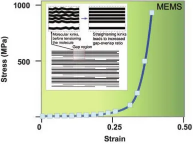
In (Fig. 1.1.3) the stress-strain relationship of a collagen fibril is shown. It was achieved stretching a fibril using a MEMS22.
Figure 1.1.3: Stress - strain relationship of a collagen fibril.8
It shows the true stress (force over instantaneous sectional area that decreases with the shrinking of the fiber) versus the Eulerian strain. The curve shares the same macroscopic aspect from the one typical from tropo-collagen molecule. A first strain region without stress, increase due to the repositioning of the bonds along the axis followed by a toe-region that can be more or less visible. After that, there is a marked increase in the slope of the curve that starts the linear region in which the deformation is still recoverable if the load is removed. Here the fibril (and its components), is aligned on the same axis of the force. During the axial deformation, the interfibrillar matrix, rich in proteoglycans, deforms in shear8. The shear stress is generated on the fibril surface.8 When the load exceeds this region, it can happen that the proteoglycan-rich interfibrillar matrix disrupts its bonds with the fibrillar matrix, and slides over its surface becoming plastic23–25. At this, point the deformation is not recoverable and removing the load will result in a permanent residual deformation.
16
The upper level of structure, the fibers, are harder to investigate because their characterization varies a lot because of different length, diameter, orientation or site26,27 (insertions sites present different fiber composition)6,15,16,28. This means that during the test these fibers are not uniformly loaded. However, studies have reported that fiber strain is recoverable until about 5% deformation29,30. As said before, along fibers (packed as bundle or fascicle) microscopic crimps are observed. It was observed that these crimps disappear at about 3% of deformation acting like another shock absorber31–33.
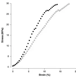
Fibers are aggregate in bundles, which can be primary (subfascicle), secondary (fascicle) or tertiary. In (Fig. 1.1.4) a stress-strain graph oh human Achilles tendon fascicle is shown.
Figure 1.1.4: Stress - strain relationship for human Achilles tendon fascicle. Filled circles = Afro American. Open circles = Caucasian34.
The upper level is represented by the whole tissue. In (Fig. 1.1.5) a typical stress-strain relationship of a tendon is shown. It shares again a similar shape compared to the characterization of its internal components.
17
Figure 1.1.5: Typical stress-strain curve of a tendon. The curve is coupled with a simple representation of the corresponding behaviour of the collagen fibers.35
In (Fig. 1.1.6) the analogue relationship is drawn for a ligament.
Figure 1.1.6: Stress - strain relationship of a human ligament (adapted from Campbell-kyureghyan et al)36.
The first part is the toe-region, in which the increasing force reduces the laxity of the collagen fibers aligning them to the direction of the load. Here the structure is “reshaped” without a true deformation. Ligaments usually present a more evident toe region (Fig. 1.1.6). This is due to their function, they have to permit the joint
18
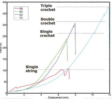
movement undergoing a certain amount of strain and then becoming suddenly stiffer to avoid non-physiological movements37. In vivo, this preload is automatically done by muscles that keep tendon deformation point at the start of the linear region37. From this point, further increasing the load, the curve enters a linear region in which the fibers are elastically deformed. Inside this region ends the physiological range of stimulation, proceeding further with the stress determines the disruption of some fibers that gradually decrease the slope of the curve (the stiffness). This is called the plastic region. The stress continues to rise until the number of broken fibers determines the failure of the structure: the curve can now show a plateau in which deformation increases without a rise of the stress, followed by the total disruption of the tendon8. This behaviour will not be the same if tested at different strain rate38. Arising the latter, the Young’s modulus that is usually chose equal to the slope in the elastic region, will increase in the same way as the failure stress38. This is due to the different mechanisms that predominate at slower or higher strain rates, a behaviour known as viscoelasticity. In the next picture (Fig. 1.1.7) an example of stress-strain behaviour of a human anterior cruciate ligament at different strain rates is proposed.
Figure 1.1.7: Stress-displacement curves at different strain rates for human ACL. The displacement rates varies from 12mm s -1 (o) to 0.3mm s -1 (△)38
Other studies39,40 show how soft connective tissues exhibit a normal creep and stress relaxation behaviour. Furthermore, it was also shown how, during a cyclical test, the stress versus strain curves for individual loading cycles became less linear and
19
with a softer slope (decreases in stiffness) during the cycles40. The hysteresis that is also present increases its area from one cycle to another one.
Once discussed the mechanical characterization of the whole tendon and its internal structures, in the next picture (Fig 1.1.8) is depicted a comparison between the stress-strain curve of tropo-collagen molecule, collagen fibril and the whole tissue. These results can vary consistently but normally it can be said that the stiffness decreases going from the lower structural level to the highest one41.
20
1.2: Tendon and ligament mechanisms of injury and common
cases
Ligament and tendon injuries are widespread problems worldwide42,43. It has been reported that more than a half of about 30 million musculoskeletal injuries worldwide involves tendons and ligaments43. The cost sustained annually by US for tendon and ligament related problems is estimated at up to 30$ billion42. It has been reported that more than 150000 procedures of treatment of anterior cruciate ligament (ACL) ruptures are done annually only in the US44. The consequences of these injuries can compromise the joint stability and, accordingly, the daily movements of patients and quality of life42,45.Tendon and ligament injuries can be both acute or chronic46. In the former scenario, the injury usually differs from tendons to ligaments for their different function. The role of tendons is to transfer the joint force of the muscle, so the most obvious danger is to suffer an acceleration or force that exceeds the tendon limit. For example, up to 90% of Achilles tendon injuries in sports are related to strong accelerations47. It was also reported that more than an half of sport-related injuries affect tendons48. These are called extrinsic factors which predominate in acute injuries46. Despite this, it was shown that in many sudden ruptures of the Achilles tendon a degenerative change that was present prior to the rupture was found49,50. Kannus and Jozsa showed how in 97% of 891 spontaneously ruptured tendons was already present a degenerative situation, compared to the 33% of 445 control tendons49. These changes is often caused by degenerative tendinopathy of which the etiology remains unclear.46 Tendinopathy is a general term used to enclose several different tendon pathologies43. Intrinsic factors such as misalignment, biomechanical faults are also associated with a presence of tendinopathy46. As showed, tendons can bear an applied stress without damage only if the strain remains in the linear region. It must be also remembered that the stress-strain behaviour of these tissues is related to the strain rate. The physiological strain for a tendon is usually up about to 5%, beyond this point the fibers begin to disrupt29. With repetitive overloading the tendon responds with either inflammation of the sheath or degeneration of its body, or both.46 Tendons have a repair mechanisms mediated by tenocytes but, they need enough time to heal
21
, caused by the low vascularization. Because of this, fatigue damages will result in a weaken and eventually in a broken tendon. Even at physiological stresses tendons suffer from microtraumas which need to be healed and may result in an injury if not enough time is given for this process, in a way similar to fatigue fractures of bones51. For example chronic problems caused by overuse of tendons are probably responsible for 30% of all running-related injuries46,52. During an injury a tendon can be partially torn, this will cause swelling, but if the patient had maintained a good strength a non-surgical repairmen is indicated53. If the tendon breaks completely the joint suffer from a complete loss of movement and the stumps retract from one another54. In these cases, a surgical procedure is mandatory. The most common cases of tendon injuries concern forearm/hand extensor and flexor tendon, the Achilles tendon, the tearing of the patellar or quadriceps tendons at the knee, and the rotator cuff tears.55
Ligaments have a different function, keeping the bones of a joint together and allow them to move only in predetermined directions. Ligament injuries are usually caused by a wrong movement normally not allowed by the joint. Ligaments injuries are a common sport accident because of the strong and sudden forces that can be suffered. The severity of the damage depends on the portion of the ligaments that was torn. Ligaments lack of blood vessels so it is hard for them, if not impossible, to recover from a serious injury without external healing56,57. A broken ligament can therefore allow a joint movement normally restricted which can lead to other serious damages. The most common ligament injuries concern the acromioclavicular ligament, the anterior cruciate ligament (ACL), the posterior cruciate ligament (PCL) and the collateral ligament.55
22
1.3: State of the art of tendons and ligaments replacement
In the last decades many attempts were made to deal with tendons and ligaments injuries: primary repair, biological grafts, synthetic grafts and tissue engineered scaffolds42,45. All of them present advantages and disadvantages, and their use varies depending on many factors like the type of the injury, the age of the patient, its occupation and others58. A common feature of these techniques is that, if the seriousness of the problem excludes a spontaneous remission of the injury, a surgery is needed. This can be done with a primary repair, which involves the suturing of the proximal and distal ends of the ruptured ligament or tendon by approximating them45. This technique, which does not include augmentation, often gives rise to many complications like decrease of the joint function and adhesions59. The results are mixed, with some successes, for example in the patellar tendon healing60, and failures that resulted in the abandonment of this method for ACL treatment in 198261. Other methods involve the tissue augmentation using biological grafts which can be divided in three groups: autograft, allograft and xenograft. Autograft are patches of tissue harvested from the own body of the patient45. They usually came from bone patellar bone tendon, hamstring tendon, quadriceps tendon and iliotibial band45. Originating from patients’ own body, problems like rejection or disease transmission are avoided but the donor-site morbidity remains a drawback62. Despite this, autograft are still the most popular used for example for ACL reconstruction45. Allograft are tissue patches collected from patellar tendon, Achilles tendon, semitendinosus or fascia Lata of another human donor63. The advantages of this technique is to reduce the operative times, to obtain larger patches but on the disadvantages it may involves diseases transmission, immune rejection, tunnel enlargement or weakness derived from the mandatory decellularization of the graft45. In the next section the two remaining techniques, synthetic biostable devices and tissue engineered bio-resorbable scaffold will be reviewed. The former is intended as a permanent replacement for the injured tissue, the latter have to promote the healing of the injury, being later reabsorbed by the body.
23
1.3.1: Synthetic biostable materials and devices for tendon and
ligament replacement
The use of synthetic materials became popular in the 1980s when researchers were looking for something which can eliminate the rejection, diseases transmission and donor-site morbidity problems57,64–69. Many of them had been abandoned later for the poor biocompatibility and long term complications revealed by studies, such failures, inflammation response because the prosthesis were identified as foreign body, implant degenerations or severe synovist.42 Among those, can be mentioned filamentous carbon implant, a cord like structure with fibers of 9-10 μm diameter which was strong and flexible. It had been used both for ligament and tendon replacement but was later withdrawn from the market because it was identified as the cause of mild effusion, pain, synovial thickening and an excessive grown of fibrous sheath over it.70
Gore-Tex was another permanent prosthesis made of thermomechanically expanded polytetrafluoroethylene (PTFE) fibers (Fig. 1.3.1). It was in braided configuration and widely used for ACL reconstruction but, after initial encouraging results, was discharged due to evidence of bone tunnel widening and a non-biologically inert behaviour in the synovial environment45. It is still used in many kind of surgery but no longer to repair or replace tendons or ligaments42.
Figure 1.3.1: A Gore-Tex implant71.
Dacron devices were also used for ACL reconstruction between 1989 and 1997 but showed high failure rate72.
24
Trevira-Hochfest is another prosthesis made of a woven PET band with longitudinal and cross-direction threads, each with 200 filaments of 23 micrometres of diameter. Although studies exhibited no synovitis and no increase of leukocytes, a slight concentration of PET wear particles and solitary multinuclear giant foreign body were observed in histological analysis73. Moreover, up to 2015, only 3 studies about the outcome of this device were found72.
Leeds-Keio graft (Fig. 1.3.2) are a non-absorbable prosthesis for tendon and ligament reconstruction that became popular since 1980s74. It is made of polyester (ethylene terephthalate) and has an open-weave architecture. Its failure stress without tissue ingrowth is 850N, its stiffness is 200 N/mm (similar to the ligament one) and it is inert but encourages the in-growth of a new ligament so it acts also like a scaffold4575.
Figure 1.3.2: A Leeds-Keio artificial ligament74.
Although it has encountered numerous drawbacks in follow up works like failure, bone tunnel enlargement, synovitis because of loosen particles, laxity and degenerative changes76, this device has also been used with favourable results to repair rotator cuff tear, knee extensor, Achilles tendon rupture, iliofemoral ligament and ankle lateral ligament42.
Ligament augmentation device (LAD) was invented by Dr. John Kennedy (Fig. 1.3.3) and it is a flat polypropylene high tenacity yarn with nine strands, each one made up of 180 fibers. It is braided in a string of 6mm width and 1mm thick77.
25
Figure 1.3.3: The Kennedy LAD ligament78.
Despite the forces tolerated by this device are lower than other synthetic permanent prosthesis45, it was proposed as an aid device aimed to bear some of the stress while the ligament is being cured by an autogenous graft or after a primary repair. However, studies reported effusion and wear particles originating from LAD. After a long follow-up it emerged that where was no stability advantages in using this device in ACL reconstruction and therefore it is not widely used anymore79.
Artelon and Sportmesh are devices made of biodegradable polyurethane urea polymer and are intended as a reinforcement for soft tissues80. It has been tested for healing of biceps, Achilles and patellar tendons and for the rotator cuff with good results both in vitro and in vivo (animals). The device showed a good degradation and tissue ingrowth was observed42.
LARS (Ligament Augmentation and Reconstruction System) is the synthetic prosthesis device for ACL repair that had more success and longevity in this 16 years on the market72. It is made of terephthalic polyethylene polyester fibers knitted in the extra-articular part and longitudinal in the articular one (Fig. 1.3.4) to be able to better provide strength and resistance to elongation45. It is normally intended for ACL81–83 repair but it was proposed also for Achilles tendon and patellar reconstruction and for acromioclavicular and collateral ligament repairs42. This device has high biocompatibility, no risky complications like foreign body rejection, synovitis, osteolysis were observed although some minor
26
complications like knee stiffness and bone tunnel enlargement were reported in animal tests84. Another advantage of this device is that it showed fibroblast in-growth aligned with the fibers in in vitro and in vivo studies. These cells (even osteoblasts-like ones) build a capsule all around the fibrous structure of the LARS connecting it to the surrounding tissue enhancing the biocompatibility85. However, the tissue in-growth is also probably responsible for a 25% loss in strength and a 70% increase in elongation but, as the same time, exhibited a J-Shaped curve very similar to the natural ligament one86.
Figure 1.3.4: LARS device in its unfolded (A) and folded (B) form.
The devices presented above, have in common the aim to mimic as better as possible the mechanical behaviour of the corresponding biological one that they have to replace or heal. This is due to the need of prevent joint instability and therefore begin the rehabilitation process as soon as possible. However, those characteristics are often quite lower than the biological original counterpart. In fact, a prosthetic device, in particular for tendon and ligament replacement, should never be stronger than the tissue that it has to replace. This to prevent that another injury can occur in another part of the healthy tendon, or in the bone or muscle. In case of an excessive stress a device replacement is advised compared to another site of injury37. For example, anterior cruciate ligament is reported to be able to bear a force of about 1250N87. Leeds-keio ligament stops at about 850N45 and LARS can reach 1000N88. However, this can be considered as an advantage of the synthetic devices because biological derived ones have dramatically lower values, ranging
27
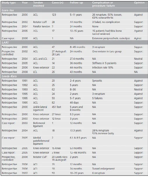
from 27 to 229N42. The aim of a prosthesis of this type is to handle at least the 50% of the maximum load of the original one so that the risk of failure during daily activities is lowered. For this need and the others presented above, (Table. 1.3.1) from a 2009 review of Chen et al.42 shows the outcome of the clinical studies of Gore-Tex, LARS and Leeds-Keio devices for tendon and ligament injuries.
Table 1.3.1: Clinical studies reports about three synthetic devices: Gore-Tex, LARS and Leeds-Keio42
One last example, concerns a synthetic device directly produced to replace a corrupted tendon. Even for tendons, the conventional method is to harvest donor ones. In this study S.Abdullah et al.89 used a device called Ortho-tape, a polyethylene terephthalate absorbable, woven tendon. Even if is non-absorbable, it has an open structure which can facilitate the tissue in-growth and is
28
supposed to be not permanent. However, after healing a patient with massive polytrauma that lost 7cm of the extensor forearm tendon, she refused the last stage of the treatment which involved the replacement of the Ortho-Tape with autografts because her function was already satisfying. The authors suggest at the end the usage of this kind of synthetic device when the tendon loss is considered “massive”.
1.3.2: Tissue engineering with 3D scaffolds
In the last years, research for tendon and ligament regeneration, has focused on a different approach: the mimicking of the hierarchical structure of the extracellular matrix of the tendon with 3D scaffolds90–96. This to encourage the growth of fibroblasts and other cells on the device and the subsequent reformation of the original tissue which then degenerates the scaffold53,95–98. This path was already taken with the use of biological graft but, as seen before, presents many drawbacks. Newer scaffolds are made via the polymerization of protein molecules like for example collagen and elastin42,99. This lead to a great cytocompatibility, biocompatibility and biodegradability. The main challenge involves the growth of the tissue aligned to the scaffold (and therefore to the tendon/ligament original fibers) avoiding a chaotic proliferation which would lead to a fibrotic tissue. Other aims are a good water uptake and adequate porosity so that the cells can penetrate the scaffold and reform the tissue not only on the surface42. Apart from the cell proliferation, these scaffolds aim to provide a structural support that can work in parallel with the tissue regeneration42,95,96; the scaffold would bear the load during the recovery of the tendon/ligament, stimulating at the same time the cells with loads in the same direction of the physiological one. The scaffold should therefore be able to withstand loads at least equal to the biological ones under normal usage that is usually in the range between 7% and 40% of the failure load53. Stiffness is also important because, to obtain the load-sharing behaviour, the biological tissue and the scaffold should present similar stiffness53,100. These specifications are hardly met all together. In the next chapter will be discussed a technique, that is becoming more and more popular in the production of biological scaffold: the electrospinning.
29
1.4: The Electrospinning technique
Electrospinning is a term coined in the early 90’s derived from the two words “electrostatic spinning”. The process was actually patented over a century ago but drew the focus of the researchers only in the last twenty years101. This is probably due to the revolution brought from the development of nanotechnology which impacted most of the branches of science. At nanometric size, the properties of materials change considerably, compared to the typical macroscopic size ones. The most important factor which have in common these new structures is the huge surface area to volume ratio102. Some examples like nanorods, nanotubes, nanowires, nanospheres or nanofibers can be mentioned102–106. In particular the electrospinning technique is suitable for its capability to produce fibers in the micro/nanoscale size and to tune their dimensions and alignment. This process can produce fibers with one to two order of magnitude greater surface area to volume ratio compared to other conventional methods such melting and dry/wet spinning93. Moreover, from a biomechanical point of view, this technique became very interesting because the nanofibers produced have a structure, a dimension and a porosity comparable to the ones found in the fibrous system of the extra cellular matrix97. This can therefore be extended to almost all of the tissues like bone, cartilages, blood vessels, nerves and, of course, tendons and ligaments95,107–109. Another advantage of this process is the ability to use a wide range of polymeric materials, both biological or synthetic ones110.
1.4.1 The Operating Principles
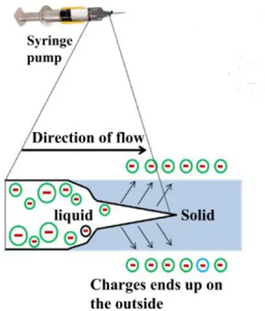
The Electrospinning technique is based on the electrostatic stretching of a polymer droplet to form ultra-fine nanofibers111. The basic configuration of an electrospinning machine (Fig. 1.4.1) is composed by a syringe pump, which control the flow rate of one or more syringes, loaded with a solution derived from a polymer (or a blend of polymers), solved in a solvent system (of one or more solvents). An high electrostatic field, usually between 5 to 30kv93, is applied from a DC power supply to the fluid via the metallic needle of the syringe (spinneret).
30
Figure 1.4.1: The Electrospinning technique112.
At a certain distance from the needle is placed the collector. This metallic part, connected to the ground, constitutes the negative. An electrostatic field is formed in this way between the needle and the collector. When the pump is activated, a droplet appears on the tip of the needle. The electric charges, inducted by the power supply on the droplet, causes instability because the reciprocal repulsion of charges is opposed to the surface tension of the liquid. These forces elongate the droplet from the original shape to form a sort of cone named as “Taylor cone” (Fig. 1.4.2).
Figure 1.4.2: Taylors’ cone formed on the droplet on the tip of the syringe. 113
When the electrostatic field is high enough to overcome the surface tension, nanofibers emerges from the Taylor cone and travel toward the collector driven by the electrostatic field. The trajectory is straight in the first section but then the
31
internal and external charge forces cause the whipping of the path of the liquid jet. This movement causes the stretching, shrinking and elongation of the viscoelastic fibers, making them even thinner113,114. The whipping movement promote also the evaporation of the solvent system, solidifying the fibers before being deposited on the collector115.
1.4.2 Working Parameters
The simple operating principle of this technique smacks against quite complex parameters tuning. The process and its outcome are in fact regulated by several factors regarding the solution, the machine setup and the environment113. The first ones include the raw polymer type, the solvent used, the concentration, the viscosity and the conductivity of the solution116. The second ones consist in the applied electrostatic field, the distance between the tip and the collector, eventually the velocity of a rotating collector, the flow rate, the needle diameter117. The environment parameters that must be controlled are the temperature and the relative humidity.
Speaking about the solution, the concentration plays an important role in the integrity of the polymer chains. If it is too low, the chains break before reaching the collector causing beads. If otherwise it is too high, the viscosity of the solution will increase causing a clog in the needle.118 The conductivity of the solution impact the shape of the Taylor cone and also the diameter of the nanofibers119120. This is quite self-evident thinking about the principle of the electrospinning. If the conductivity of the solution is too low, it will not react to the electric field and the cone will not be formed. A conductive solution will instead have free charges which can move inside the liquid and therefore deform the droplet to form the cone. Even the air-travel from the tip to the collector can take place only if the solution reacts enough to the electrostatic field. Speaking about the solvent, it has to be able to completely dissolve the raw polymer. It should also have a moderate boiling point because if it is too high the jet will dry up too early before leaving the tip. Otherwise, if it is too low, even the solvent will reach the collector melting the fibers that are already deposited on it originating beads121113.
32
The most important machine parameter is the voltage applied to form the electrostatic field122. The optimal value varies from polymer to polymer. Raising the voltage, theoretically the fiber will be stretched more before reaching the collector causing a lower fiber diameter. This is true until a critical value; exceeding it will result in the formation of beads and thicker nanofibers because of the increased jet velocity113. The flow rate is a critical value and should be balanced with the rate of formation of the nanofibers from the droplet. Increasing it too much will result again in the formation of beads or unspun droplets that will fall from the tip because of the gravity123. The correct distance from the needle to the collector must be determined in order to obtain a stable smooth and uniform flux of nanofibers. If the distance is kept to short, this will lead to defective and large-diameter nanofibers113, or in a not complete evaporation of the solvent system.
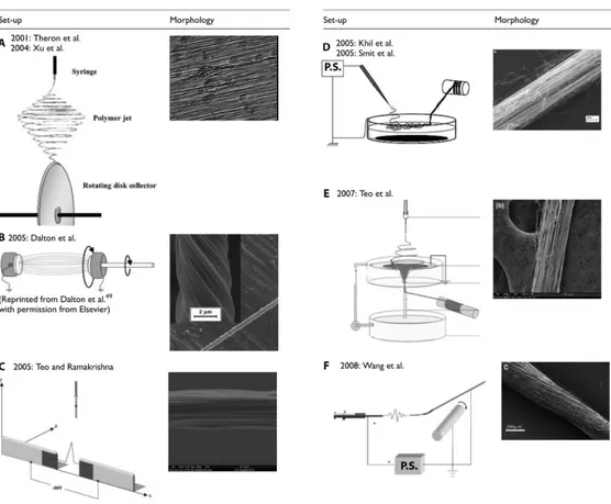
The collector is a crucial part of the electrospinning machine. Upon it shape, position and movements, depends the morphology and alignment of the nanofibers101. Different collection systems are also used to obtain different architectures of nanofibers: bundles, that are groups of straight nanofibers aligned in the same direction, or yarns, that are aligned but also contain an imparted twist in order to enhance the mechanical properties101,124. The most basic collector consists of a metal grounded plate that draw the nanofibers toward it125 (Fig. 1.4.1). The fibers, in this way, deposit in a random configuration on the plate surface126. Other techniques, involving high-speed rotating drum collectors, are mainly used to obtain stretched and aligned fibers126. Besides these two major categories of collectors, many different techniques had been researched to obtain fibers with a desired alignment of with better mechanical features111,116 (Fig. 1.4.3). Theron et al127 and Xu et al.128 proposed a rotating disk collector with a tapered edge in order to obtain aligned nanofibers due to the high velocity of the disk. The drawbacks are that the length of the fibers is limited and necking was observed101. Dalton et al.129 used grounded parallel annular collectors in the path of the jet with one of them rotating in order to produce yarns (twisted fibers) of up to 50mm length. Teo and Ramakrishna111 proposed two negatively charged steel blades perpendicular to the direction of the jet to obtain highly aligned fibers. The methods above are only able to obtain short bundles or yarns. Other methods were proposed with the aim to
33
produce continuous fibers. For example, Khil et al.130 and Smit et al.131 directed the jet inside a water bath with a grounded electrode and collected the continuous yarn with a take-up roller. Teo et al.132 also directed the jet into the water but they then collected the yarn from a hole on the base of the water collector. Wang et al.90 reported a method to directly collect continuous bundle in the air by placing a rotating drum at a set distance. The speed of rotation must be investigated to match the production and the collection rate.
Figure 1.4.3: Several collector types for electrospinning. Modified from O’Connor et al.101
Lastly, the environmental parameters act an important role on the outcome of electrospinning. Relative humidity is recommended to be under 35%93: if it is too high it will often lead to beaded fibers or impair the electrospinning at all113. The solidification process of the fiber in the jet also depends on the humidity of the air. Temperature can change the rate of evaporation of the solvent and therefore even change the viscosity of the solution before the spinning process. If it is increased, this will lead to a decrease in the diameters of fibers for both these causes113.
34
1.4.3 Electrospinning in tendon and ligament tissue replacement
At the present day, many researches are currently being carried out on synthetic and resorbable scaffolds for tendons and ligaments, but very few animal trials had been evaluated. To improve the mechanical properties and the biocompatibility, in the last years the research on scaffolds focused its attention on the electrospinning technique97. Electrospun scaffolds have a surface area to volume ratio higher than with other production methods98,101,133. This is crucial to obtain a better cell penetration and proliferation in the scaffold111,128. The alignment and the dimension of the electrospun fibers can also be tuned to mimic as much as possible the ones of the extracellular matrix. This will also enhance the mechanical properties of the scaffolds with fibers aligned to the load. With this production method, many attempts have been made92,93,97,102,108, trying to reproduce every part of a tendon/ligament. Fibers and fascicles are the starting low level structures that had been investigated101 aiming to mimic their characteristics and mechanical behaviour94,134–144. Tendon/ligament-to-bone insertion site were also investigated due to their particular composition107,145,146. Upper level structures like multiscale tendons had been later investigated147–149, trying also to mimic the tendon/ligament sheath91,150.
This technique permits the production of nanofibers from a wide range of polymers, both synthetic and biological151. One common problem of electrospun proteins like collagen and elastin is the loss of these molecules after ageing in physiological environment138. Recently Sensini et al.94 aimed to the production of an electrospun scaffold for the human Achilles tendon two different blends of PLLA and Collagen (75-25 and 50-50) were cross linked ad hoc to both reduce the collagen early loss and increase the mechanical properties before seeding them with human tenocytes.
35
1.5: Developments and applications: soft-robotics – an overview
1.5.1: Soft Robots: actuation modes and prototypes
In this chapter, Soft Robotic will be discussed. This can be considered a newly born field that can be a promising alternative way of use of synthetic tendons. This area of research is in continuous growth and relies on the development of robotic devices mimicking the mechanisms of movement and locomotion of soft bodied animals found in nature152. Classic robots, have structures made of stiff materials such as steel, aluminium, titanium or alloys, hard polymers connected with rigid links and operated by numerical control machines (CNC) and motors. They have the advantages of being very precise, fast and powerful when used in their specific field, but lack adaptability when the environment of work is not well known153. In soft-robotic, robots differ in many features compared to the conventional ones because they are designed using soft materials, in order to mimic the living beings, we find in nature. To allow movements, negative pressures systems, chemical reactions or advanced polymers, substitute the classical motors. For example, when considering animals with a structural skeleton, this rigid component is almost never directly exposed to the environment. As a matter of fact, the soft tissue which covers it constitutes the majority of body mass. Indeed, only 11% of the weight of an adult human male is made by the skeleton, whereas more than 42 % is soft tissues152. Just like living being’s evolutionary curve adapted to their complex and unpredictable environment, the same rule applied to soft robotics. Indeed, an important principle for soft robotic is compliance matching; as proposed by a perspective from Majidi154, compliance matching “is the principle that materials that come into contact with each other should share similar mechanical rigidity in order to evenly distribute internal load and minimize interfacial stress concentrations”. Soft robots are usually made of materials with a Young’s modulus ranging from 104 to 109 MPa153, contrarily to conventional ones characterized by a modulus over 1010 MPa154. This leads to the ability to safely interact with humans and the environment and to prevent or absorb collisions even if unable to precisely detect the position of their target. They are deformable and soft but with an adaptable shape, which is a keystone in the scalability of their use. However, their
36
soft structure also represents a disadvantage; as a matter of fact, this implies an inability to produce high forces and makes them harder to be controlled153.
In this section, a first overview on the actuation and transmission modes of soft robots will be discussed. A brief on the prototypes of soft robots will follow. The kind of actuation is possibly the most important feature as it is very challenging to produce localized forces without being able to use rigid parts like, for example, an electric motor.
One of these actuation systems is obtained using SMAs (Shape Memory Alloys), a particular type of alloys which can change shape when warmed through an electric current. When the stimulus is removed, they revert to their original shape. These have many advantages like having a high force-weight ratio, a high resistance to fatigue and they can also be used as sensors. The drawbacks are the high currents needed and a marked hysteresis155. An example of a SMA coil is shown in (Fig. 1.5.1 B)
Another actuation system is based on SMPs (Shape Memory Polymers) which have the same functioning of SMAs but can be triggered by different types of stimuli: chemical, electric, thermic, light or magnetic. Their advantages are being flexible and often biocompatible.
Electro Active Polymers (EAPs) can also be used as they exhibit a change in shape or size in response to an electric field. They can be used both as actuators of sensors. Being able to undergo a large amount of deformation while sustaining large forces, EAPs are an interesting way to mimic biological muscles; in fact, they have even higher power density. The drawbacks of these materials are the slow response time and, once again, the high currents needed for them to work156153.
One of the simplest ways to actuate soft robots are hydraulic or pneumatic systems, which are based on the introduction of liquids or air inside expansion chambers embedded in the structure so that these parts will show different stiffness; in this way it can be produced a change in the shape and/or a folding.
Bearing in mind that this work is focused on tendons, which transfer the force made by actuators (muscles), it will be investigated a particular actuation system of soft robotics in which the forces are cable-driven in a similar way. This technique is usually chosen to design hybrid soft robots, which are made of soft components and
37
are often actuated by rigid motors. With cables it can be detached, even with a long range, the motor from the actuation target site (like with fingers and corresponding muscles in the forearm). Many problems could be overcome this way; for example, the weight and the volume can be lowered leading to less inertia and, accordingly, a faster movement response157. On the other hand, the main drawback is that it is very challenging to minimise or eliminate all backlashes, leading to potential instability.
Firstly, it will now be overviewed the soft robots that were designed as prototypes in order to investigate materials and locomotion strategies rather than being made for a specific use. They are all inspired by different soft animals.
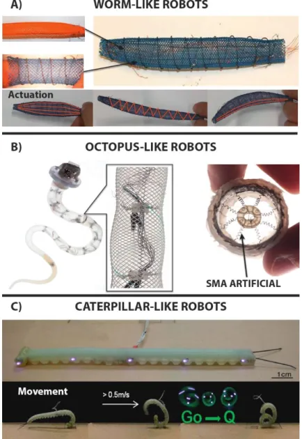
The first prototypes involve worm-like robot, based on the principle that worms are fixed-volume hydrostats and their locomotion is achieved by the contraction of the longitudinal muscles: this will shorten their body and at the same time increases its diameter; conversely contracting the circumferential muscles they decrease the diameter therefore elongating the body. One example is the Meshworm158, it uses SMA like actuators. This robot can steer using longitudinal SMA coil muscles in place of the tendons (Fig. 1.5.1 A).
Octopus-like robots are based on the movement techniques of ones of the most complex and evolved soft-bodied animals: the cephalopod. They have the ability to completely modify their shape to pass through tiny holes or cracks. The manipulators inspired by these animals were developed on the concept of compartmentalized deformations used to produce locomotion. They can be actuated by pneumatic muscles159 or, alternatively160, SMA springs are considered; these can be arranged both transversely and longitudinally to produce local deformation, and cables are employed to obtain the global bending, like tendons. These are surrounded by a plastic fiber braid (Fig. 1.5.1 B).
Caterpillar-like robots differ from worms because they have a totally different muscular system and imply different locomotion strategies. They only exhibit longitudinal and oblique muscles used to locally increase or decrease the body stiffness. The same principle is mimicked by the GoQbot161 (Fig. 1.5.1 C), made of silicone rubber and capable to flex ventrally thanks to two tensile SMA coils which can separately control the anterior or posterior flexion. When this
38
motion is executed quickly enough it can produce a ballistic rolling locomotion up to 2 m/s for a 10-cm long robot.
Figure 1.5.1: Animal-inspired soft robots. A) Meshworm: structure and actuation modes152.
B)Octopus-like robot. mechanical structure of the arm, allowing for local and global deformations while keeping the arm shape. Focus on the SMAs radial muscles which causes radial restriction152. C)GoQBot. It has a composite body consisting of several mixtures of silicone.
GoQbot simulating a ballistic rolling. The name "Go Q" is due to its shape assumed during the movement 161
These examples were developed to propose a different interaction of rigid robots with a partially known environment. In fact, some of the characteristics of these robots such as the locomotion system, the actuators, the compliance materials
39
etc. are considered attractive by many fields of research. One of this is, of course, the biomedical field. It can be imagined miniaturized robots for body exploration, drug delivery, minimal invasive surgery, soft wearable robots or prosthesis (like manipulators for hand replacement).
1.5.2: Soft exoskeletons and prosthesis
Inspired from the soft robot prototypes presented above, the development of some soft exoskeletons has begun with a possible large impact on movement rehabilitation. This strategy has been successfully employed in the construction of many wearable soft robots in which the function of the rigid frame, showed in the conventional robots, is carried out by the natural skeleton. In literature these devices are often referred to as soft exoskeletons, soft wearable robots, exosuits, exotendons etc. and, in the vast majority of cases, they are actuated with a cable-driven system. In the following part some examples of these devices are presented, focusing on their design.
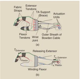
BiomHED (Biomimetic Hand Exotendon Device162) is proposed to assist stroke survivors in which significant upper extremity impairment is prevalent163. The goal of this exoskeleton designed by Lee et al. is to help patients in producing complex, task-oriented hand gestures with high intensity, since it has been shown that this leads to maximized outcomes in stroke rehabilitation162. The main problem is that survivors often have uncontrolled spasticity and weakness with a typical clenched-hand posture. This point is where the BiomHED helps patients, trying to assist their movements reflecting the dynamic functions of the impaired hand. As previously mentioned, this is a cable driven soft exoskeleton that is worn as a glove. The actuation is achieved by DC motors placed on the forearm and the force is transferred by “exotendons”: stainless steel cables (SAVA 1024164), four for each finger, that mimic the geometry of the four main natural finger muscle-tendon units (Fig. 1.5.2).
40
Figure 1.5.2: Exotendon configuration of the BiomHED: (a) dorsal view, (b) radial view, (c) palmar view, and (d)magnified view of the dorsal thermoplastic guides that route exotendons
(FET=Finger ExoTendon; TET=Thumb ExoTendon)162.
Exosuit (Fig. 1.5.3) is a novel soft-cable-driven device proposed by Asbeck et al.165166whose goal is to assist walking. It is worn like clothing and can generate moments at the ankle and the hip in the order of 18% to 30% of the corresponding natural ones produced during a walk. Even this device lacks rigid parts, and this leads to a minimization of its weight as it uses the natural skeleton as a frame. Indeed, a soft device pretending to actuate forces on the body presents challenges, because the body is compliant and cannot stand high pressures in a comfortable way.
Figure 1.5.3: (a) Views of the upper suit with components labelled. Arrows indicate places where it can be adjusted to fit different sizes of individual. (b) Views of the foot attachment165
41
It attaches around the waist and above the knee. The actuation is applied by a motor located in a backpack with electronics and batteries, making it a portable device. The force is transferred to the back of the calf and the waist through webbing straps. Again, from the back of the calf, a Bowden cable starts extending downwards to another webbing strap placed on the back of the heel. A key feature of this device is that the forces generated are both active and passive; the active ones by the motor and the Bowden cable and the passive ones by the natural kinematics of walking through the elastic straps. From the work of Asbeck the material which is made the cable by is not known.
Exoglove (Fig. 1.5.4), proposed by Hyunki In et al.167168 , is another device based on the structure of a human hand. Its design consists of two tendons for each finger and for the thumb, fixed in position with fabric straps that act as pulleys. The straps length and position can be adjusted but they are inextensible in order to maintain the moment arms of the tendons. The cables run inside Teflon tubes to minimize the friction. Even in this case the actuation is obtained with a motor placed far, reducing the weight to 194g and the consequent inertia. The results presented by this work, conducted on a healthy subject, showed a pinch force of 20N and a wrap grasp force of 40N during daily life tasks. The glove could also grasp objects with a maximum size of 76mm. The authors propose this device for people incapable of opening or closing their hands but who are still able to use upper limb joints like shoulders, elbows and wrists. It is also proposed to assist individuals with medium to low finger spasticity, only if the degree of spasticity is the same for all fingers.