INDICE
THE TEST SECTION VESSEL S100 ... 5
HEATERS ... 7 THERMOCOUPLES ... 8 DRAINING LINE ... 8 S200 STORAGE TANK ... 8 S100PRE-CONDITIONING ... 9 PRE-HEATING IN S100 ... 9 MELTCONDITIONINGINS200 ... 9
FILL AND DRAIN ...10
TYPICALTEST ...10
RANGE OF OPERABILITY ...10
INTRODUCTION
The HLM facility SOLIDX (SOLIDification eXperiment) was designed to collect the first experimental data on Lead freezing for the GEN-IV nuclear systems.
The facility contains Lead as working fluid, and typically will operate close to the freezing temperature of 330 °C to study the freezing/melting phenomena from a thermo-fluid dynamic point of view.
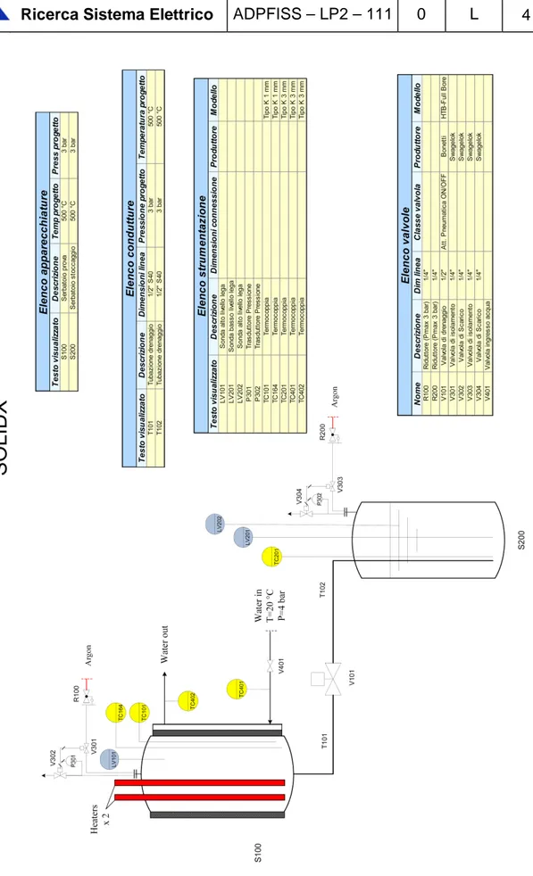
The SOLIDX facility conceptual design was carried out according to the P&ID shown in Figure 1. The main components and systems of the facility are:
1) The experimental vessel S100 with all the instrumentation (main process to be investigated);
2) The fill and drain system: a. Fill & drain line b. V101 valve
c. The storage tank S200
3) The auxiliary gas system to ensure a proper cover gas and to perform fill&drain operation
The SOLIDX facility is made by two small vessels S100 and S200 with a fill&drain line and a valve. The whole facility will be manufactured with austenitic steel AISI304.
THE TEST SECTION VESSEL S100
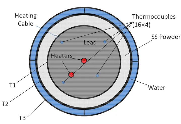
The test vessel S100 is the test section of the facility. S100 where Lead will be frozen during the experimental tests. A transversal top-view section of S100 is reported in Figure 2.
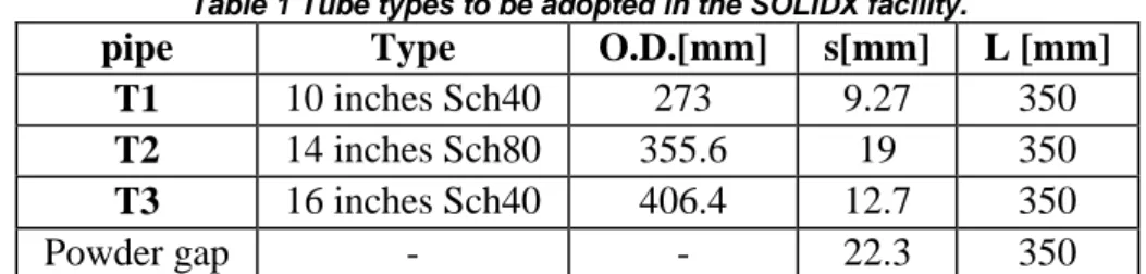
The test section is made of three concentric commercial pipes T1, T2, T3 described in Table 1.
The total height of the pipes is 350 mm, with a liquid lead level at 290 mm from the bottom. A 10 inches flange ANSIB16.5 WN 330 lb will close the test section. In the blind flange lots of penetrations are manufactured to located the heating elements and the instrumentation. The facility can dismounted and re-assembled in order to operate for maintenance and upgrade.
Table 1 Tube types to be adopted in the SOLIDX facility.
pipe Type O.D.[mm] s[mm] L [mm]
T1 10 inches Sch40 273 9.27 350
T2 14 inches Sch80 355.6 19 350
T3 16 inches Sch40 406.4 12.7 350
Powder gap - - 22.3 350
The pipe T1 will contain the liquid lead for the tests, while the gap between T1 and T2 (22 mm) will be filled with stainless steel powder to control heat transfer. The gap between T2 and T3 is divided in 4 sectors and it will be filled with flowing water to cool the system. This system will ensure the possibility of asymmetric cooling; keeping into account that one of the heaters is also asymmetric, several different kind of experiments can be carried out.
The gap dimensions and the system thermo-fluid dynamic process was designed by conjugate heat transfer CFD simulations, while the thermal properties of the SS powder are derived by the experimental campaign in the TXP facility. A 1 kW heating cable will be located in T1 external wall to heat up the facility during the pre-heating.
A draining line will connect the test section S100 to the drain vessel S200. The design parameters of S100 are the following:
Design temperature: 500 °C Operating temperature: 400 °C Working fluid: Lead
Design pressure: 1,50 bar Operating pressure: 1,45 bar Cover gas: Argon
Cover gas overpressure: 50 mbar Total volume: 20 liters
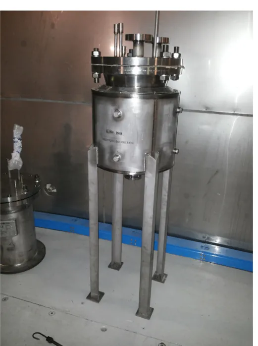
The final technical drawing of S100 is reported in the annex file ‘214-670 SOLIDX S100.dwg’. A picture of the test section vessel S100 is reported in Figure 3.
Figure 3 Picture of the SOLIDX test section vessel S100.
HEATERS
The heaters to be inserted in the test section S100 are of great importance for the experiment. The heating elements will be placed in the following positions:
Element H1 in symmetric central position;
Element H2 at the middle of the radius, i.e. 63 mm from the center;
The heating elements features are reported in Table 2. Swagelok connectors will ensure the sealing in the cover gas.
Table 2 Electric and geometrical features of the heaters.
Active length 250 mm
Power 2500 W
THERMOCOUPLES
The thermocouples will be 1 mm OD of ‘K’ type and will be placed along 4 tubes at 16 different vertical levels from the bottom of S100, see Figure 2. The radial position of the 4 support tubes is ¾ of the radius (95.4 mm) and ½ of the radius (63.6 mm) from the center.
DRAINING LINE
The draining line is manufactured with AISI304 1/2" S40 pipes with a manual valve. The line has the following design data:
Design temperature: 500 °C Working temperature: 400 °C Working fluid: Lead
Design pressure: 3 bar Working pressure: 1,5 bar
S200 STORAGE TANK
The storage tank S200 is closed by a blind flange with to allocate all the instrumentation and in-out gas line
S200 was designed according to the following data: Design temperature: 500 °C
Operating temperature: 400 °C Working fluid: Lead
Design pressure: 3 bar Operating pressure: 2 bar Cover gas: Argon
Cover gas gauge overpressure: 100 mbarg-2 barg Total volume: 20 liters
The present section describes the main procedures for the logical control of the SOLIDX facility.
The main procedures include all the transient and steady state conditions to be performed in the facility to prepare the facility or for the normal operation, and to assess the goals of the experimental campaigns. The procedures define the process of the facility and the logical control (DACS) must operate this process.
The operating procedures for SOLIDX are simple if compared with complex loops or large experimental facility. The small scale is typical of a Lab facility. A short description is reported. Water valves V401a-d are manual valves, as well as the draining Lead valve V101.
S100PRE-CONDITIONING
Pipes and components must be pre-heated with the heating cables set-point to Tpre1=100 °C
and this temperature must be kept constant for a few hours for the first time the facility is operated. The time derivative of the temperature during the heating process can be fixed to 10 °C/h, to mitigate thermal stresses in the loop.
After the pre-heating, keeping components at Tpre1=100 °C, 10-15 Cleaning Cycles must be performed. Each Cleaning Cycle consists on loop pressurization with Argon/Argon H2 at 1 barg gauge pressure. This operations must be performed both in S100 and S200.
The operation clean the facility and the steel from the oxygen and avoids strong oxidation of Lead. The conditioning is operated by in-out gas valves V301, V302 and V303, V304, by setting alternatively 1 barg and 200 mbar set points.
PRE-HEATING IN S100
The facility can be operated both with LBE and Lead, but first will be operated in pure Lead. With S200 filled and in cover gas and V101 closed, both vessels have a fixed pressure set point of 0.2 barg. For the pre-heating, the set temperature of S100 is fixed to Tpre2=400 °C,
and the components are heated-up by the heating cables with a heating rate of 10 °C/h. The pressure increase ratio can be evaluated through the perfect gas law and it is of the order
p400°C/p100°C~673/373~1.8, i.e. the final maximum pressure for a constant volume closed
system is 1.8 bar absolute, 0.8 barg gauge. Nevertheless, the overpressure is discharged by the hydraulic guard during the operation and the overpressure peak should not pass 0.2 barg gauge.
At the end of the pre-heating, the loop is filled with Argon at constant temperature
Tpre2=400°C and pressure p(gauge)=0.2 barg.
MELTCONDITIONINGINS200
The S200 temperature must be larger than 330 °C to avoid lead freezing. The set temperature of the storage tank is fixed to TpreS300=400 °C, and the components are heated-up by heating
cables with a heating rate of 10 °C/h. The S100 cover gas region will be stably conditioned with Argon/Argon H2 to avoid oxygen contamination from environmental air.
At the end of the pre-heating, S200 is filled with liquid LBE at TpreS300=400°C with an Argon
FILL AND DRAIN
The filling of the facility is carried out by opening the manual valve V101 and by pressurizing S200 cover gas up to 2 barg about by setting P302 set point. P301 set point is fixed to 0.2 barg. The level sensors LV201, LV201 will monitor the change in level for the storage tank S200, while the level sensor LV101 will provide the signal for the filling of S100. When S100 is filled, V101 is closed. The facility can now be operated for a test.
The draining of the facility is performed by setting P301 and P302 set points to 0.2 barg and by opening V101. The liquid metal will flow in S200 by gravity. Then V101 will be closed.
TYPICALTEST
A typical test can be performed with S100 filled, V101 closed and the system kept warm by heating cables with a set point of 400 °C for S100. The control thermocouple of the heating cable is placed in the gap between T1 and T2. The temperature of the Lead is monitored by TC101-TC164.
In a typical test, the heating cable for S100 is switched off and one of the two heaters is switched on at a constant power from 0 to 2500 W (maximum power per heater). Then V401 with tap water is open in one of the 4 sectors to be cooled. A flow meter will monitor the water flow rate. With a time constant of about half an hour the system would reach the thermal equilibrium, and the process thermocouples TC101-TC164 would show thermal stratification and solidification front.
RANGE OF OPERABILITY
Due to the presence of two heaters and 4 sections (90°) for cooling a large range of operational conditions can be achieved with the facility. With 4 power levels per heater and 4 cooling sections, a basic test matrix of 4Χ4Χ4=64 cases can be processed.
CONCLUSIONS
A basic description of the SOLIDX facility was provided in the document. The operating modes and all the main operational procedures for managing and performing tests were also depicted. The range of operability was discussed.
The facility will be in operation within 2015 and it will provide the first experimental results for Lead solidification and the experimental data will be useful for validate computer codes. At a second stage, the facility can be operated in LBE to collect the same kind of data.