ScienceDirect
Available online at www.sciencedirect.com
Procedia Engineering 199 (2017) 2597–2602
1877-7058 © 2017 The Authors. Published by Elsevier Ltd.
Peer-review under responsibility of the organizing committee of EURODYN 2017. 10.1016/j.proeng.2017.09.364
10.1016/j.proeng.2017.09.364
© 2017 The Authors. Published by Elsevier Ltd.
Peer-review under responsibility of the organizing committee of EURODYN 2017.
1877-7058 Available online at www.sciencedirect.com
ScienceDirect
Procedia Engineering 00 (2017) 000–000
www.elsevier.com/locate/procedia
1877-7058 © 2017 The Authors. Published by Elsevier Ltd.
Peer-review under responsibility of the organizing committee of EURODYN 2017.
X International Conference on Structural Dynamics, EURODYN 2017
Experimental and analytical study on elevating working platform
Luigi Solazzi*
Università degli Studi di Brescia, Dipartimento di Ingegneria Meccnica e Industriale, Via Branze 38, Brescia 25123, Italy
Abstract
This paper describes the research performed about the dynamical behavior on the mobile elevating work platform (MEWP). In particular, this research was inspired by that accident happened during a pruning operation. A big branch of three fell down and bumped the basket of MEWP. The consequent dynamical actions have made the operator jump out of the basket of MEWP. The main object of this work is to characterize the dynamic behavior of this machine (height=34 m, working load limit =200 kg) in order to estimate the actions induced by the branch on the MEWP. This load condition is not contemplated in the standards used for the design of this machine. For this purpose many experimental, analytical and numerical analyses were performed. In order to characterize the dynamical behavior of the machine (real damping, stiffness of the global arm and the sliding blocks positioned between each arms, etc.), on the similar MWEP, about 20 accelerometers and strain gauges were applied; subsequently the machine was subjected to different movements (extension and rotation the arms and the jib). The MEWP was subjected to geometrical relief with the aim to carry out the solid model necessary for finite element model (f.e.m.) analyses; which are performed using the parameters acquired in the previous step. The f.e.m. results were compared with the values obtained from the strain gauges. A lumped parameter model was created in order to apply the load condition induced by the branch to the jib. Numerical and analytical results show that in the geometrical configuration of MEWP (when the accident occurred), the acceleration of the basket is greater than gravity and it justifies the operator jumping out of the basket. The results achieved led to a revision of the standards (in a specific technical committee) both for designing this machine in order to consider this exceptional load condition and for designing the safety equipment for MWEPs operators.
© 2017 The Authors. Published by Elsevier Ltd.
Peer-review under responsibility of the organizing committee of EURODYN 2017. Keywords: Dynamic characteristics; dynamic model; lifting equipment; elevating working platform.
* Corresponding author. Tel.: +39-030-3715577; fax:+39-030-3702448. E-mail address: [email protected]
Available online at www.sciencedirect.com
ScienceDirect
Procedia Engineering 00 (2017) 000–000
www.elsevier.com/locate/procedia
1877-7058 © 2017 The Authors. Published by Elsevier Ltd.
Peer-review under responsibility of the organizing committee of EURODYN 2017.
X International Conference on Structural Dynamics, EURODYN 2017
Experimental and analytical study on elevating working platform
Luigi Solazzi*
Università degli Studi di Brescia, Dipartimento di Ingegneria Meccnica e Industriale, Via Branze 38, Brescia 25123, Italy
Abstract
This paper describes the research performed about the dynamical behavior on the mobile elevating work platform (MEWP). In particular, this research was inspired by that accident happened during a pruning operation. A big branch of three fell down and bumped the basket of MEWP. The consequent dynamical actions have made the operator jump out of the basket of MEWP. The main object of this work is to characterize the dynamic behavior of this machine (height=34 m, working load limit =200 kg) in order to estimate the actions induced by the branch on the MEWP. This load condition is not contemplated in the standards used for the design of this machine. For this purpose many experimental, analytical and numerical analyses were performed. In order to characterize the dynamical behavior of the machine (real damping, stiffness of the global arm and the sliding blocks positioned between each arms, etc.), on the similar MWEP, about 20 accelerometers and strain gauges were applied; subsequently the machine was subjected to different movements (extension and rotation the arms and the jib). The MEWP was subjected to geometrical relief with the aim to carry out the solid model necessary for finite element model (f.e.m.) analyses; which are performed using the parameters acquired in the previous step. The f.e.m. results were compared with the values obtained from the strain gauges. A lumped parameter model was created in order to apply the load condition induced by the branch to the jib. Numerical and analytical results show that in the geometrical configuration of MEWP (when the accident occurred), the acceleration of the basket is greater than gravity and it justifies the operator jumping out of the basket. The results achieved led to a revision of the standards (in a specific technical committee) both for designing this machine in order to consider this exceptional load condition and for designing the safety equipment for MWEPs operators.
© 2017 The Authors. Published by Elsevier Ltd.
Peer-review under responsibility of the organizing committee of EURODYN 2017. Keywords: Dynamic characteristics; dynamic model; lifting equipment; elevating working platform.
* Corresponding author. Tel.: +39-030-3715577; fax:+39-030-3702448. E-mail address: [email protected]
2598 2 Luigi Solazzi / Procedia Engineering 00 (2017) 000–000 Luigi Solazzi / Procedia Engineering 199 (2017) 2597–2602
1. Introduction
The present paper concerns the study of the dynamical behavior of the mobile elevating working platform (MEWP). The dynamic behavior of the cranes, and in general for the lifting equipment, is a very important problem [1,2]. Dynamic effects on the machine can be generated by different phenomena such as moving loads [3,4,5], the action of the wind [6] or by the action induced by an earthquake [7]. The increase of the stresses induced by the dynamic effects can be particularly critical for instability phenomena (local or global) or overturning the machine. For example, if in the process of lifting a specific load there is a sudden breakage of the rope, which binds the load, the resulting backlash could overturn the machine. The vibrations on the structure induced by the load handling have also consequences on the fatigue life of the machine because they generate more fatigue cycles that add to the fundamental ones (lifting and lowering the load). In this work, the dynamic effect of the lifting platform had been generated during normal operation of plant pruning. The cut branch fell on the basket of the lifting platform and then to the ground. The sudden removal of the load from the basket has generated a dynamic effect that made the operator thrown out from the basket. The operator suffered serious injuries and so it was not possible to ask to worker the exact dynamic of the accident. The problem is then to estimate the accelerations on the operator as a result of the sudden load release.
For this purpose the work was developed by different steps. The first step was to measurement the geometry of the structure in order to made solid models needed for subsequent numerical finite element analysis. In order to identify the real dynamic behavior of the MWEP a series of accelerometers and strain gauges were installed on a similar machine with the aim to identifying the parameters that characterize the machine. In particular by experimental acquisitions, it has been possible to determinate the real parameters of the machine such as the stiffness of the sliding blocks of the telescopic arms and the effective damping in the machine. The experimental evaluation of the dynamic behavior of the machine was possible by running a series of predefined movements, like for example, the extension and rotation (with respect to the vertical plane and the horizontal plane) of the arms.The numerical analyzes were performed including in the f.e.m. model based on the parameters obtained from experimental tests. The results made it possible to realize a parametric lumped model in order to apply the motion’s law to the the jib, assuming that induced by the fall of the cut tree branch. The results of the numerical and analytical analysis showed that in the geometrical configuration of the platform in which presumably the accident happened, the maximum acceleration of the basket was far greater than the gravity and this justified the operator of being thrown out of the basket.
2. Description of the MWEP
The object of this research is a mobile elevating working platform with a maximum height of 34 m and a maximum load capacity of 2000 N. The machine is shown in Fig. 1. The extending structure is composed of five elements (arms) + jib element to which the basket is bound. The length of each extending element is about 7 m, whereas the length of the jib element is about 2.7 m. The largest cross-section of the element of extending arms is rectangular 400 x 280 mm, 4 mm thick.
Luigi Solazzi / Procedia Engineering 199 (2017) 2597–2602 2599 2 Luigi Solazzi / Procedia Engineering 00 (2017) 000–000
1. Introduction
The present paper concerns the study of the dynamical behavior of the mobile elevating working platform (MEWP). The dynamic behavior of the cranes, and in general for the lifting equipment, is a very important problem [1,2]. Dynamic effects on the machine can be generated by different phenomena such as moving loads [3,4,5], the action of the wind [6] or by the action induced by an earthquake [7]. The increase of the stresses induced by the dynamic effects can be particularly critical for instability phenomena (local or global) or overturning the machine. For example, if in the process of lifting a specific load there is a sudden breakage of the rope, which binds the load, the resulting backlash could overturn the machine. The vibrations on the structure induced by the load handling have also consequences on the fatigue life of the machine because they generate more fatigue cycles that add to the fundamental ones (lifting and lowering the load). In this work, the dynamic effect of the lifting platform had been generated during normal operation of plant pruning. The cut branch fell on the basket of the lifting platform and then to the ground. The sudden removal of the load from the basket has generated a dynamic effect that made the operator thrown out from the basket. The operator suffered serious injuries and so it was not possible to ask to worker the exact dynamic of the accident. The problem is then to estimate the accelerations on the operator as a result of the sudden load release.
For this purpose the work was developed by different steps. The first step was to measurement the geometry of the structure in order to made solid models needed for subsequent numerical finite element analysis. In order to identify the real dynamic behavior of the MWEP a series of accelerometers and strain gauges were installed on a similar machine with the aim to identifying the parameters that characterize the machine. In particular by experimental acquisitions, it has been possible to determinate the real parameters of the machine such as the stiffness of the sliding blocks of the telescopic arms and the effective damping in the machine. The experimental evaluation of the dynamic behavior of the machine was possible by running a series of predefined movements, like for example, the extension and rotation (with respect to the vertical plane and the horizontal plane) of the arms. The numerical analyzes were performed including in the f.e.m. model based on the parameters obtained from experimental tests. The results made it possible to realize a parametric lumped model in order to apply the motion’s law to the the jib, assuming that induced by the fall of the cut tree branch. The results of the numerical and analytical analysis showed that in the geometrical configuration of the platform in which presumably the accident happened, the maximum acceleration of the basket was far greater than the gravity and this justified the operator of being thrown out of the basket.
2. Description of the MWEP
The object of this research is a mobile elevating working platform with a maximum height of 34 m and a maximum load capacity of 2000 N. The machine is shown in Fig. 1. The extending structure is composed of five elements (arms) + jib element to which the basket is bound. The length of each extending element is about 7 m, whereas the length of the jib element is about 2.7 m. The largest cross-section of the element of extending arms is rectangular 400 x 280 mm, 4 mm thick.
Fig. 1. (a) elevating working platform; (b) experimental test; (c) load chart for MWEP.
Luigi Solazzi / Procedia Engineering 00 (2017) 000–000 3
3. Experimental texts
The experimental tests on the MWEP were conducted by applying a series of strain gauges and accelerometers to the different arms and the jib (Fig. 2) and subjecting the machine to specific movements. The tests were conducted with and without a vertical load equal to 2000 N inside the basket.
Fig. 2. (a) MEWP; (b) accelerometer on the jib articulation; (c) accelerometer at the end of the arm (d, e and f) strain strain gauges on the arms. The experimental measurements were carried using n° 4 triaxial accelerometers “CrossBow” with range +- 2g and n° 16 strain gauges “HBM” (120 ) with grid of 6 mm. Other accelerometers have been applied to the basket, to the jib junction and to the head of the first two arms. The strain gauges were applied to the jib and to the main arm, see Fig. 2. The data acquisition was carried out at 250 Hz.
3.1. Experimental results
A first result collected from the experimental tests was the estimation of the damping present in the structure, i.e. the overall damping that depends both on the material and the type of junction between the various elements. In particular, the damping value depends on the sliding block present between different arms. This variable was evaluated by the acceleration and by strain gauge data and using the logarithmic decrement method.
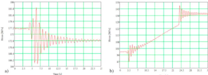
An example of the graphs of strain gauges acquired is shown in Fig. 3. They refer to the strain gauge positioned in the first arm of the lifting platform. Fig. 3 (a) shows the trend of the measured stresses caused by the removal of a load of 200 N present in the basket. The Fig. 3 (b) shows the trend of the stress for the same strain gauge in the phase of starting and stopping the rotation of the arm in the vertical plane, starting from the horizontal positions. In Fig. 3 it is possible to observe how the value of the stress changes from the position with and without load in the basket and the vibrations induced both by the application of the load and the start and stop the movement.
The graph of Fig. 4 shows the trend of the accelerations detected in correspondence of the accelerometer 1 and 2. The experimental test consists of the rotation of the arm in the vertical plane. As in the graph of Fig. 3, Fig. 4 (b) and (c) shows the trends of the accelerations from the start to stop of the movement. The average component of acceleration changes during the rotation of the arms because the component of the acceleration of gravity changes compared to the normal of the arm. Fig. 4 (d) and (e) displays accelerometers 1 and 2 assuming as a loading scenario, the jump of an operator (weight 800 N) from the basket (impulsive load given by the operator jump). From the overlap of the graphs, Fig. 4 (f) shows how in this specific configuration the accelerations in the basket are much higher than the ones present in correspondence of the articulation of the jib, so the horizontal component is much higher than the vertical component.
The stiffness is a fundamental parameter validating the finite element model and for studying the parametric lumped model. This parameter is difficult to evaluate because it depends on the deformation of the different arm components (bending rigidity) and on the stiffness of the sliding blocks between the arms. Numerous experimental tests were carried out with the purpose of estimating this parameter (Fig. 5) by measuring the displacement present in the basket in two different configurations with and without an additional load of 1000 N (applied in the center of the basket). In this way it has been possible to estimate the value of the stiffness in different geometrical configurations.
2600 Luigi Solazzi / Procedia Engineering 199 (2017) 2597–2602 4 Luigi Solazzi / Procedia Engineering 00 (2017) 000–000
Fig. 3. Stress trend evaluated by strain gauge (a) application of a load (b) rotation of the arms.
Fig. 4. (a) accelerometers position; (b) acc. 1; (c) acc. 2: (d) acc. 1; (e) acc. 2; (f) overlap of the two graphs.
Fig. 5. (a), (b) and (c) different geometrical configuration of MWEP; (d) load inside the basket.
The stiffness and damping values are depending on the geometrical configuration of MEWP and varying from 101.7 kN/m to 3.6 kN/m for stiffness and 341.2 (N/m*kg)0.5 to 63.9 (N/m*kg)0.5 for damping.
4. Lumped parametric model
The lumped parametric model developed to study the problem is visible in Fig. 6. It is a two degree of freedom model. This model is similar to the one developed for studying the dynamic effects in the boom crane [5]. The first coordinate refers to the displacement at the height of the arms, in correspondence of the articulation of the jib. The second coordinate refers to the displacement present at the center of the basket. The coordinates x1 and x2 refer to the movement induced by the bending respectively for the arms and for the jib.The 𝛼𝛼 and 𝜗𝜗 coordinates respectively refer to the inclination of the machine arms and the jib referred to the horizontal plane. The assumption made by this scheme reflects the position and orientation of two accelerometers placed on the machine.
Fig. 6. (a) lumped parameter model; (b) diagram for determination of the absolute velocity of M.
Luigi Solazzi / Procedia Engineering 199 (2017) 2597–2602 2601 Luigi Solazzi / Procedia Engineering 00 (2017) 000–000 5 The velocity of the point M in the absolute reference system will be given by the following formula:
𝑣𝑣𝐴𝐴𝐴𝐴𝐴𝐴= √𝑣𝑣𝑚𝑚2 + 𝑣𝑣𝑀𝑀2 + 2𝑣𝑣𝑚𝑚𝑣𝑣𝑀𝑀co s[90° − (𝛼𝛼 + 𝜃𝜃)] (1)
The system can be solved by means of the Lagrange equations. The same procedure used to estimate the parameter c2 was repeated to determine the parameter c1, i.e. from the experimental data by means of the logarithmic decrement method. The value is about c2= 630 (N/m*kg)0.5. This value is significantly higher than the value c1 and is justified by the presence of the articulated system, driven by a hydraulic cylinder, which allows the rotation of the jib, which is particularly dissipative. The magnitude of m and M parameters to be used in the lumped parametric model were determined using the solid models of the machine made on the basis of experimental measurements, in order to estimate the overall weight of the machine. The m and M values were obtained by calculating the natural frequencies in the lumped parametrical model and comparing these values with those obtained experimentally. By f.e.m analyses it was possible to perform the modal analyses, verify the magnitude of the natural frequencies, and obtain the values of the modal mass participation. These values obviously depend on the geometric configuration of the machine. The total weight of the arms is equal to about 10500 N while the overall weight of the jib is equal to about 500 N.
5. Application to the accident case
The geometrical configuration of the machine in which the accident occurred presents a rearing up angle equal to 40 ° (𝛼𝛼 = 50 ° and 𝜗𝜗 = 0 °) and a height of about 13.5 m. The weight inside the basket is equal to 800 N being present only one operator. The parameters used in the lumped parameter model are shown in Table 1.
Table 1. Parameters for application the lumped parametric model. k1 [kN/m] c1 [(N/m*kg)0.5] m [kg] k2 [kN/m] c2 [(N/m*kg)0.5] M [kg] 9.9 106.4 360 216.3 612.3 90
It was assumed that the weight of the branch was equal to F, and a force with the following trend (eq.2) was applied to the lumped parametric model. This trend of application and removal the load was assumed arbitrarily.
The load was transferred to the basket in 0.5 s and after a limited time (3 s), it was completely removed. 𝐹𝐹(𝑡𝑡) = { 𝐹𝐹 0.5𝑡𝑡 𝑠𝑠𝑠𝑠 0 < 𝑡𝑡 ≤ 0.5 𝐹𝐹 𝑠𝑠𝑠𝑠 0.5 ≤ 𝑡𝑡 < 3 0 𝑠𝑠𝑠𝑠 𝑡𝑡 ≥ 3 (2)
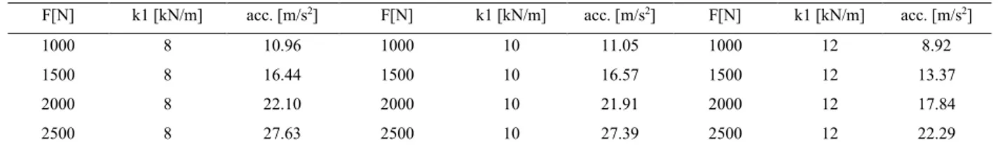
To increase the reliability of the results acquired by lumped model, the some analyses were performed by finite element model. This was performed by a simplified CAD model of the structure prepared by SolidWorks® software; the numerical analyses were performed using the Autodesk Simulation® software. The finite element models performed in different geometrical configurations are made by approximately n ° 400000 linear brick elements for a total of about 580000 degrees of freedom. It is important to underline that the values of the natural frequencies are aligned with the values for the first vibration modes of lifting equipment, like in [5,7]. In particular, the first natural frequency for arm is 1.6 Hz, while for jib is 7.4 Hz; the damping coefficient is 5.35% for arm and 6.6% for jib. Tab. 3 reports the peak values of the acceleration as a function of the F values or of the weight of the branch and the stiffness of the arms (k1).
Table 3. Maximum value of acceleration for different conditions.
F[N] k1 [kN/m] acc. [m/s2] F[N] k1 [kN/m] acc. [m/s2] F[N] k1 [kN/m] acc. [m/s2]
1000 8 10.96 1000 10 11.05 1000 12 8.92
1500 8 16.44 1500 10 16.57 1500 12 13.37
2000 8 22.10 2000 10 21.91 2000 12 17.84
2602 Luigi Solazzi / Procedia Engineering 199 (2017) 2597–2602 6 Luigi Solazzi / Procedia Engineering 00 (2017) 000–000
6. Results
According to the condition led by the sudden release of the load or, for the particular circumstance, when the branch has fallen to the basket, the results obtained by the analytical model have justified the accident, from the technical point of view (acceleration of the basket greater than the gravity).
The sensitivity analysis performed to the weight of the branch and to the stiffness of the arms indicated the acceleration depends linearly on the magnitude of the load. The relation between the acceleration and the stiffness of the arms is not linear; if the load increases the acceleration increases as well, while the stiffness of the structures decreases, although the stiffness, (in this range of values) is less important than the magnitude of the load.
7. Conclusions
This current research describes the dynamical behavior of a mobile elevating work platform, trying to justify the response of the structure during a particular condition such as the pruning operation, where a big branch of a tree can fall, bumping the basket of the MEWP. The causes determining the overhang of the operator, considering the “falling branch condition”, were discovered by knowing the accelerations of the drum, as the result of an estimated “branch load” applied to the machine. The research was carried out both by means of experimental, analytical and numerical methods in order to achieve a dynamic reliable model of the machine.
The experimental analyses were performed on a similar machine by positioning a series of accelerometers and strain gauges. The numerical analyses were carried out by developing a finite element model of course after having designed a solid model of the machine. The analytical analyses were carried out through the implementation of a lumped parametrical model with two degrees of freedom.
The analyses carried out showed that the acceleration to which the operator was subjected during the fall of the branch, in the geometrical configuration in which the accident happened, is superior to the gravity one thereby justifying the backlash that has thrown the operator out of the basket. At the end of the work, the sensitivity analysis performed to evaluate the reliability of the data (mainly focused on the position of the basket and on the weight of the branch), confirmed the acceleration of the basket was much higher than that the gravity in most of the geometrical configurations.
The current standards for the design of the lifting equipment don’t include this exceptional loading condition and therefore the working platforms have never been (virtually) subjected to any impulsive action. For this reason, the technical considerations displayed by this research and in particular, related to the results of the parametric lumped model, have been proposed to a specific technical committee for the technical review of the standards for the MEWP design.
References
[1] V.K. Augustaitis, V. Gican, A. Jakstas, B. Spruogis, V. Turla, Research of lifting equipment dynamics, Journal of Vibroengineering, 16 (issue 4) (2014), pp. 2082-2088.
[2] S.T. Chen, Z.X. Sun, X.D. Li, H.L. Wang, Dynamic characteristic analysis of girder hoisting machine structure based on linear stiffness ratio, Journal of Railway Engineering Society, 31 (issue 11) (2014), pp.77-81 and 97.
[3] S.C. Hu, N.B. Zou, S. Ouyang, W.Y. Zhang , Simulation analysis about dynamic characteristics of crane’s jib system based on the lifting loads, Advanced Materials Research, 910 (2014), pp. 304-307.
[4] V. Gašić, N. Zrnić, Considerations of various moving load models in structural dynamics of large gantry cranes, FME Transactions, 41 (2013), pp. 311-316.
[8] L.Solazzi, G. Incerti, C. Petrogalli, Estimation of the dynamic effect in the lifting operations of a boom crane, proceedings of the 28th European Conference on Modelling and Simulation –ECMS 2014, Brescia, Italy, 27-30 May, 2014.
[6] S. Bošnjak,N. Zrnić, B.Dragović, Dynamic response of mobile elevating work platform under wind excitation, J. of Mechanical Engineering, 55 (2009), pp.104-113.