single-mode vibration damping of
piezoactuated structures
Paolo Bisegna1, Giovanni Caruso2, and Franco Maceri1
1 University of Rome “Tor Vergata”, 00133 Rome, Italy
2 Institute for Technology in Construction, ITC-CNR, 00137 Rome, Italy
Abstract. This paper deals with single-mode passive damping of piezoactuated structures. The problem of shunting in the best way a piezoelectric actuator is discussed, and a new passive shunt circuit, given by the parallel of an inductance and a capacitance in series to a resistance, is here proposed. For a sufficiently high piezoelectric coupling coefficient, it is analytically shown to be more performant than the classical resistive-inductive shunt circuit, in the sense that it guarantees an higher exponential time decay rate of the free vibrations.
1
Introduction
Piezoelectric materials, due to their lightness and easy integrability to the host structure, have been intensely applied for vibration control in special applications, like aeronautic and aerospace structures. Different strategies to vibration control are available: passive, active or hybrid [2,4]. Passive vibra-tion damping, which is dealt with in this paper, is intrinsically stable, cheap and easy to be implemented by using piezoelectric actuators. The actuators are bonded to the mechanical structure and shunted to suitable external elec-tric circuits containing at least resistive components, able to dissipate elecelec-tric energy [7,5,6]. The basic idea can be easily understood looking on a simple, linearly elastic strut equipped with a piezoelectric patch and vibrating along an eigenmode. Due to the piezoelectric effect, at the electrodes of the piezo-electric device, acting as a capacitor, an alternating voltage arises. It is quite a natural idea to connect the electrodes on a passive circuit, in order to ob-tain an alternating current and an energy dissipation. The simplest shunt is the resonant one, tuned on the same frequency of the motion to be damped, in order to obtain, at that frequency, the lowest, purely resistive impedance and the maximum current for the induced voltage. It appears that the basic requirement is to dissipate as much energy as possible in the lowest time, with a circuit easy to be implemented, stable and cheap. Another require-ment may concern the performance of the shunt in a frequency band large enough to include different structural eigenmodes.
In [7] both a resistive (R) and a resistive-inductive (RL) shunt circuit applied to the vibration damping of a single-mode piezoactuated structure
were thoroughly examined. A slight variation of the RL series circuit, i.e. the RL parallel circuit, was presented in [8]. Many authors were involved in the analysis of those circuits [9,10] and some modifications were proposed in order to improve their performances [11–13].
A major problem arises from the values of the electrical parameters of the piezoelectric components commercially available, because the inductors needed to tune the resonant circuit at the mechanical frequencies of interest are usually very high. Consequently, some authors [3] were considering the use of synthetic inductors. Later, others synthetic components of special shunt circuits were proposed, including negative capacitances [14].
At the present time, the RL series circuit is generally accepted as the most performant passive shunt in vibration damping on a single eigenmode. Aim of this paper is to show that different schemes can be proposed, which are more performant than the RL circuit, for a sufficiently high piezoelec-tric coupling coefficient. This result is obtained by choosing as performance index, and therefore optimization criterium, the exponential time-decay rate (ETDR) of the free vibrations. The maximization of such an objective func-tion can be obtained, due to the linearity of the differential model of the electromechanical system, by means of an application of the pole placement technique to the system transfer function.
The new passive shunt circuit presented here in order to outperform over the classical RL shunt circuit, is indicated by R(L||C) and is shown in Fig. 1. It is composed by the parallel of an inductance L and a capacitance C, in series to a resistance R.
The analysis is analytically carried out, and closed-form expressions for the optimal values of the electrical components and of the achieved ETDR are determined. This analysis turns out to be very useful for design purposes and effective comparisons with the classical RL series shunt circuit, in terms of optimal values of circuit parameters and achieved ETDR.
2
The electromechanical model
A single-degree-of-freedom mechanical system equipped with a piezoelectric device shunted on a passive circuit is here considered. The governing equa-tions, in the Laplace domain, are [1,13]:
(s2m + k
mm)x + kmeV = sxo+ ˙xo (1a)
q = −kmex + CpV (1b)
V + sZq = 0 (1c)
In the domain of the Laplace variable s, x is the mechanical variable, V is the electric potential and q is the electric charge on the piezoelectric elec-trode. Moreover, m is the mass, kmm is the mechanical stiffness, kme is the
C
L
R
C
p
q
p
Piezoelectric element
A
B
Fig. 1. R(L||C) shunt circuit
and velocity. The electric initial conditions are assumed to vanish, for the sake of simplicity. Equation (1a) is the dynamic equilibrium of the mass m, equation (1b) is the free electric charge balance equation on the piezoelectric surfaces and equation (1c) is the Kirchhoff equation of the shunt electric cir-cuit connected to the piezoelectric electrodes, whose impedance is denoted by Z.
In the case of a complex structure, equations (1a)–(1b) can be regarded as modal equations describing the evolution along a chosen eigenmode. Ac-cordingly, the involved parameters can be evaluated by means of a suitable finite element formulation (e.g., [15]).
The shunt circuit described in the Introduction and reported in Fig. 1 is considered here. Its impedance is:
Z = R + 1
(sL)−1+ sC (2)
By substituting V from equation (1b) into equations (1a) and (1c), and taking into account the above expression of Z, the governing equations are rewritten as follows: µ s2m + kmm+k 2 me Cp ¶ x + kme Cp q = sxo+ ˙xo (3a) kme Cp x + µ 1 Cp + sR + s3LRC + s2L 1 + s2LC ¶ q = 0 (3b)
In order to study the system (3a)–(3b) and to optimize the electrical parameters R, L and C in order to achieve the maximum ETDR, it is con-venient to rewrite it in a dimensionless version. By letting x = xX, q = qQ and s = sS, where the capital letters mean dimensionless quantities and the
overlined letters are the corresponding dimensional scales, a dimensionless version of (3a)–(3b) can be written as:
(S2+ 1 + κ2)X + κ Q = sXo+ ˙Xo (4a)
κ X +1 + ρS + λ(1 + c)S
2+ λcρS3
1 + cλS2 Q = 0 (4b)
where the following dimensionless parameters have been introduced:
κ = pkme kmmCp , c = C Cp , ρ = RωmCp, λ = ωm2CpL, ωm= r kmm m , x q = s 1 kmmCp, s = ωm (5)
and Xo, ˙Xo are the dimensionless counterparts of xo, ˙xo, respectively. In
equation (5), κ is the piezoelectric coupling coefficient and depends only on the piezoactuated structure, c is the ratio between the capacity C of the shunt circuit and the piezoelectric capacity Cp, λ is the dimensionless inductance
and ρ is the dimensionless resistance.
3
Optimization of the shunt circuit
In this section an optimization of the dimensionless quantities c, λ and ρ is performed to maximize the exponential time decay rate of the solution. The characteristic polynomial p(S) of the dimensionless system (4a)–(4b) reads explicitly as: p(S) = S5+1 + c cρ S 4+ µ 1 cλ + 1 + κ 2 ¶ S3 +λ(1 + κ 2) + λc + 1 cλρ S 2+1 + κ2 cλ S + 1 cλρ (6)
The system poles Si are the roots of the above polynomial p(S). They
have a nonpositive real part, due to the inherent passivity of the system. The exponential time decay rate of the free vibrations is given by:
ETDR = −maxi{Re(Si)} (7)
where Re denotes the real part of a complex number. Consequently, the optimization problem amounts to searching for the values of λ, ρ and c which maximize the ETDR for each fixed value of κ. It is here remarked that the poles of the dimensionless system (4a)–(4b) are proportional to the poles of (3a)–(3b) trough the time-scale coefficient ω−1
3.1 Analysis of the asymptotic case c → 0
In this section it is proved that the addition of a small capacitance in parallel to the inductance L of a RL series shunt circuit increases the ETDR, provided that the piezoelectric coupling coefficient is sufficiently high. To this end, an asymptotic analysis near c = 0 is developed.
In the case c = 0, the impedance Z in equation (2) reduces R + sL. Consequently, the dimensionless system (4a)–(4b) reduces to the case of a
RL shunt circuit and the characteristic polynomial becomes [7,13]:
p(S) = S4+ρ λS 3+ (1 + κ2+1 λ)S 2+ρ λ(1 + κ 2)S + 1 λ (8)
which can be also obtained by taking the limit of cρp(S) for c → 0. Ac-cordingly, the optimal values of λ and ρ can be computed, in the practical situation 0 < κ < 2, by enforcing that p(S) has two coincident couples of complex conjugate roots:
p(S) = (S2− 2x
1S + x21+ x22)2 (9) Here x1 and x2 are, respectively, the real and the imaginary part of the complex conjugate roots, and the ETDR coincides with −x1. The optimal values of the parameters ρ and λ and the corresponding ETDR are [1,13]
λ = 1 (1 + κ2)2, ρ = 2κ (1 + κ2)32 , ETDR = κ √ 1 + κ2 2 (10)
Returning now to the case c > 0 and limiting the analysis to the case of
c close to 0, the following factorization of the fifth-order degree polynomial p(S) is assumed:
p(S) = (S2− 2x
1S + x21+ x22)2(S − x3) (11) Here x3 is a real root which approaches −∞ when c → 0: hence, for each fixed small value of c, the ETDR is still the opposite of x1.
By identifying the expressions (6) and (11) of p(S), five nonlinear equa-tions in the six unknowns x1, x2, x3, λ, ρ and c are obtained, where κ is intended to be kept fixed. By an elimination procedure, a single nonlinear equation f (x1, c) = 0 is obtained, which implicitly defines a function x1(c). The derivative ∂x1/∂c can be obtained by a straightforward application of Dini’s theorem. In particular, for c = 0 this derivative is given by
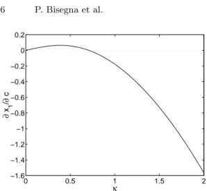
∂x1(c) ∂c ¯ ¯ ¯ c=0 = − κ 4 2κ2− 1 √ 1 + κ2 (12)
and is plotted versus κ in Fig. 2.
It is emphasized that ∂x1/∂c|c=0 is negative for κ > 1/
√
2. Hence, x1 is a decreasing function of c around c = 0. As a consequence, for κ > 1/√2, adding a small capacitance in parallel to the inductance increases the ETDR,
0 0.5 1 1.5 2 −1.6 −1.4 −1.2 −1 −0.8 −0.6 −0.4 −0.2 0 0.2 κ ∂ x 1 / ∂ c
Fig. 2. Behaviour of ∂x1/∂c versus κ for c = 0
proving that the proposed shunt circuit performs better than the classical
RL one. It is emphasized that this conclusion is not limited by the assumed
factorization (11) used in the computations. Indeed, if another factorization of p(S) exist yielding a higher ETDR than the one supplied by (11), a-fortiori that ETDR would be better than the one provided by the RL shunt circuit. 3.2 Optimization of the R(L||C) shunt circuit
0 0.5 1 1.5 2 0 0.5 1 1.5 2 2.5 3 κ ETDR RL circuit RL||C circuit
Fig. 3. Behavior of ETDR versus κ
In this section an analytical optimization of the proposed circuit is per-formed. In particular, the optimal values of ρ, λ and c, and the corresponding
0 0.5 1 1.5 2 0 0.2 0.4 0.6 0.8 1 κ λ RL circuit RL||C circuit
Fig. 4. Behavior of λ versus κ
0 0.5 1 1.5 2 0 0.1 0.2 0.3 0.4 0.5 0.6 0.7 0.8 0.9 κ ρ RL circuit RL||C circuit
Fig. 5. Behavior of ρ versus κ
ETDR, are determined for given values of the piezoelectric coupling coeffi-cient κ.
As a consequence of equation (12), it turns out that, for κ ≤ 1/√2 no increase in performances can be obtained with respect to the RL circuit if a small capacitance C is added in parallel to the inductance L. Accordingly, in this range the optimal value of c, near c = 0, is just zero, and the optimal expressions for the other parameters are those relevant to the RL circuit, given in equation (10).
When κ > 1/√2, equation (12) implies that there exists an optimal value of c, strictly greater than zero, yielding the optimal ETDR. In order to ap-ply the pole placement technique to find the optimum, a special factoriza-tion of p(S) is needed. This factorizafactoriza-tion is suggested by the case of the resistive-inductive shunt circuit. In that case, two coincident couples of
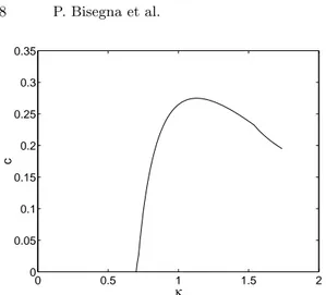
com-0 0.5 1 1.5 2 0 0.05 0.1 0.15 0.2 0.25 0.3 0.35 κ c
Fig. 6. Behaviour of c versus κ
plex conjugate roots can be collocated. In the R(L||C) case, the characteristic polynomial p(S) is fifth-order degree. Hence, an extra real root exists and, accordingly, the factorization (11) is considered. By identifying the expres-sions (6) and (11) of p(S), five nonlinear equations can be written involving the six unknowns x1, x2, x3, ρ, λ and c. These equations define implicitly x1,
x2, x3, ρ and λ as functions of c. Thus, the extra condition of the stationarity of x1= −ETDR with respect to c can be added. In the range κ > 1/
√
2 an admissible solution to this stationary condition can be found and is reported in Appendix 4.1.
For κ = κ ' 1.53, computed in Appendix 4.1, it turns out that x1 =
x3, so that all the real parts of the poles are coincident. When κ > κ the factorization (11) is no longer optimal, since x3 would became greater than
x1. Hence, the optimal factorization enforces that the double complex poles and the real pole have the same real part:
p(S) = (S2− 2x
1S + x21+ x22)2(S − x1) (13) In this case, there are only five unknowns x1, x2, ρ, λ and c involved into the five nonlinear equations coming from the polynomial identification, which determine the admissible solution reported in Appendix 4.2.
Finally, for κ = ˜κ ' 1.75, computed in Appendix 4.2, there exists a choice
of the electrical parameters such that the polynomial p(S) exhibits a fifth-order real pole, and the best possible ETDR supplied by the proposed shunt circuit is attained.
The values of the ETDR, λ, ρ and c are respectively plotted in Figs. (3)– (6) versus the piezoelectric coupling coefficient κ, and compared to the cor-responding quantities relevant to the RL circuit. From Fig. 3 it turns out that, for κ > 1/√2, the R(L||C) circuit exhibits a greater ETDR than the classical RL circuit. Moreover the difference between the performances of the
two shunt circuits increases with increasing κ. From Figs. 4 and 5 it follows that the optimal inductance and resistance relevant to the R(L||C) circuit are almost the same as the ones required by the RL shunt circuit. Finally, Fig. 6 shows that c has a maximum of the order of 0.3; hence, the capacitance C to be put in parallel to the inductance L is less than 30% of the piezoelectric capacity Cp.
The above results show that the proposed shunt circuit performs better than the RL shunt circuit for κ > 1/√2, and requires values of the electrical component very close to the ones required by the RL circuit.
4
Conclusions
In this paper the problem of choosing the optimal shunt circuit for single-mode passive vibration damping was discussed. It was shown that, at least for sufficiently high coupling coefficients κ, the traditional RL circuit is not the most effective. Indeed, the performance of a new shunt circuit proposed here is definitely better. It is emphasized that in modern applications very high values of κ can be achieved, for instance by using negative capacitances. In multi-modal vibration damping the basic design concepts remain the same and therefore the problem of choosing the optimal shunt circuit must be faced also in that case.
Acknowledgments
This research was developed within the framework of Lagrange Laboratory, an European research group between CNRS, CNR, University of Rome “Tor Vergata”, University of Montpellier II, ENPC and LCPC.
References
1. Caruso, G. (2000) Laminati piezoelettrici, modellazione, algoritmi di calcolo ed ottimizzazione della risposta dinamica. Doctoral Thesis, Dep. of Civil Engineer-ing, University of Rome “Tor Vergata”.
2. Agnes, G. S. (1995) Development of a modal model for simultaneous active and passive piezoelectric vibration suppression. J. Intell. Mater. Syst. Struct. 6, 482–487
3. Edberg, D. L., Bicos, A. S., and Fechter, J. S. (1991) On piezoelectric energy conversion for electronic passive damping enhancement. Proc. Damping ’91 (San Diego, CA, 1991) paper GBA-1.
4. Bisegna, P., Caruso, G., Del Vescovo D., Galeani, S. and Menini, L. (2000) Semi-active control of a thin piezoactuated structure. SPIE Proc. 3989, 300–311 5. Inman, D. J. (1997) Vibration suppression trough smart damping. Proc. of the
Fifth International Congress on Sound and Vibration, Adelaide, South Australia 6. Lesieutre, G. A. (1998) Vibration damping and control using shunted
7. Hagood, N. W. and von Flotow, A. (1991) Damping of structural vibrations with piezoelectric materials and passive electrical networks. J. Sound Vib. 146, 243–268
8. Wu, S. Y. (1996) Piezoelectric shunts with a parallel R-L circuit for structural damping and vibration control. SPIE Proc. 2720 259–269
9. Park, C. H. and Inman, D. J. (1999) A uniform model for series R-L and parallel R-L shunt circuits and power consumption. SPIE Proc. 3668 797–804
10. Park, C. H. (2003) Dynamics modelling of beams with shunted piezoelectric elements. J. Sound Vib. 268 115–129
11. Park, C. H., Kabeya, K. and Inman, D. J. (1998) Enhanced piezoelectric shunt design. Trans. ASME 57 149–155
12. Caruso, G. (2000) Smorzmento passivo di vibrazioni mediante materiali piezoelettrici e circuiti elettrici risonanti. Proc. XXIX National Congress AIAS, Lucca, Italy, 307–316
13. Caruso, G. (2001) A critical analysis of electric shunt circuits employed in piezoelectric passive vibration damping. Smart Mater. Struct. 10 1059–1068 14. Tang, J. and Wang, K. W. (2001) Active-passive hybrid piezoelectric networks
for vibration control: comparisons and improvement. Smart Mater. Struct. 10 794–806.
15. Bisegna, P. and Caruso, G. (2000) Mindlin-type finite elements for piezoelectric sandwich plates J. Intell. Mater. Syst. Struct. 11 14–25
Appendix
4.1 Optimization according to factorization (11) with stationary
x1
For 1/√2 < κ < κ the optimal value of x1is given by
x1= − p
maxi{zi} (14)
where zi are the positive real roots of the polynomial in the unknown z
q(z) = 4096(κ2− 8)2z8 +2048(−7κ6+ 42κ4− 336κ2+ 128)z7 +512(36κ8+ 91κ6+ 635κ4+ 448κ2+ 192)z6 +16(κ12− 644κ10− 5324κ8− 9720κ6− 5520κ4+ 896κ2+ 1024)z5 −8(1 + κ2)(7κ12− 230κ10− 1210κ8+ 2270κ6 +6238κ4+ 2912κ2− 128)z4 +κ2(1 + κ2)2(73κ10+ 684κ8+ 6964κ6+ 14544κ4+ 8096κ2− 256)z3 −κ4(1 + κ2)3(43κ8+ 488κ6+ 1596κ4+ 1024κ2− 16)z2 +κ8(1 + κ2)4(11κ4+ 76κ2+ 44)z −κ12(1 + κ2)5 (15)
The optimal values of the electrical parameters are given by
λ = −(1 + κ
2− 4x
1x3− 4x21− 2y)y2x3
c = λ (4x1x3+ 4x21+ 2y − 1 − κ2) (17) ρ = (1 + c) −c(x3+ 4x1) (18) where x3= − 1 4 y2− 2y − 2κ2y − 4x2 1κ2+ 2κ2− 4x21+ 1 + κ4 x1(−1 + y − κ2) (19) Λ = y2x 3−4x23x1−20x21x3−2yx3+x3+x3κ2−16x31−8yx1+4x1+4x1κ2(20) and y is given by the maximum positive real root of the following polynomial in the unknown y r(y) = y5+ (4x21− 4κ2− 5)y4+ (10 + 16κ2− 12x21κ2− 8x21+ 6κ4)y3 +(32x4 1− 10 − 4κ6− 16x41κ2+ 12x21κ2− 18κ4− 24κ2+ 12x21κ4)y2 +(5 + 8x2 1− 4κ6x21+ 18κ4+ 12x21κ2− 48x41+ 16κ2 +κ8− 48x41κ2+ 8κ6)y −1/4 − 3x2 1κ2− 3κ4/2 − κ6− κ2+ 4x41− 3x21κ4 +4κ4x41− κ8/4 − x21+ 16x61κ2+ 16x61+ 8x41κ2− κ6x21 (21) The imaginary part of the double complex conjugate roots is x2= ±
p
y − x2 1. The present factorization supplies an optimal ETDR as long as the real root x3 is less than or equal to the real part x1of the double complex conju-gate roots. The limit κ in Section 3.2 is just defined as the value of κ which makes the equality prevail. It is given by the real positive solution of the following system in the unknowns κ and x1
A(4x2 1κ2− 2 + κ4− κ2− 2x21) = 6x21+ 6x41+ κ2x12− 5κ4x21+ 4κ2x41 A(6x2 1+ 13κ2+ 9κ6− 32x41+ 20κ4− 8x41κ2+ 2 + 16x21κ4+ 22x21κ2) = −8κ2x6 1− 3κ6− 62κ4x21+ 34κ2x41+ 32x61− 26κ6x21− κ8 +22x41− 10x21− κ2+ 12κ4x41− 3κ4− 46κ2x21 (22) where A =px2 1(1 + x21+ κ2).
4.2 Optimization according to factorization (13) For κ < κ < ˜κ the optimal value of x1 is given by
x1= − √ 2 2 s 2κ6− 3κ2+ κ4− 2 +√4κ12− 8κ8+ 2κ10− 6κ6 1 + 2κ2 (23)
and the optimal parameters are λ = (8x 2 1+ 2y − 1 − κ2)y2 −y2+ 40x2 1+ 10y − 5 − 5κ2 (24) c = λ 8x2 1+ 2y − 1 − κ2 (25) ρ =1 5 1 + c (−x1)c (26) where y = −2x2 1+ κ2+ 1 + 2 q x4 1+ κ2x21+ x21 (27)
The present factorization is admissible as long as two double complex conjugate roots exist. When κ → ˜κ, given by
˜ κ = r 24 + 6√5 − 2 25 √ 5(125 + 30√5) (28)
the imaginary part x2 = ± p
y − x2
1 of those conjugate roots tends to zero, and for κ = ˜κ the characteristic polynomial p(S) admits five coincident real