10-Gb/s
Operation of a Colorless Self-Seeded
Transmitter
Over More Than 70 km of SSMF
Paola Parolari, Lucia Marazzi, Marco Brunero, Mario Martinelli, Romain Brenot, Anaelle Maho, Sophie Barbet,
Giancarrlo Gavioli, Gael Simon, Fabienne Saliou, and Philippe Chanclou
Abstract— Operation of a network-embedded colorless self-tuning transmitter for wavelength division multiplexing (WDM) networks is experimentally demonstrated at 10-Gb/s data rate. Colorless operation is achieved by self-seeding an O-band reflec-tive semiconductor optical amplifier (RSOA) with the feedback signal reflected at the remote node WDM multiplexer filter. In particular, the transmitter exploits a 2-Faraday rotators configuration to ensure polarization insensitive operation and allowing for the exploitation of high gain O-band RSOAs, which present a very high polarization dependent gain. Two different multiplexers and various lengths of drop fibers constituted the network-embedded transmitters. Transmission up to 72 km of standard single mode fiber has been demonstrated at 10 Gb/s, confirming the absence of chromatic dispersion penalties as expected from the choice of the O-band operation.
Index Terms— Passive optical network (PON), reflective semiconductor optical amplifier (RSOA), colorless transmitter, fronthaul.
I. INTRODUCTION
Wavelength division multiplexing passive optical networks (WDM PONs), offering point-to-point connectivity and
independence of multiple access protocol to share the medium, are good candidates for supporting the new fronthaul fiber network requirements [1]. The necessity to allow inventory and maintenance cost reduction will favor WDMPON solutions based on colorless transceivers. We present recent results of a network embedded self-tuning colorless transmitter, based on a self-seeding architecture [2] exploiting an O-band high-polarization dependent gain (HPDG) reflective semiconductor optical amplifier (RSOA). Due to the presence of a HPDG device, a two-Faraday topology is exploited to ensure stability of the signal state of polarization (SOP) within the optical cavity, which is established between
the optical reflector at the remote node (RN) and the mirror at the reflective semiconductor optical amplifier, placed at the optical network unit (ONU) [3]. Recent works [4]–[6] have demonstrated the effectiveness of this approach to cope with the SOP evolution due to the unavoidable birefringence associated with the distribution fiber, which connects the ONU and the RN WDM multiplexer, namely an arrayed waveguide grating (AWG).
Manuscript received December 13, 2013; revised January 10, 2014; accepted January 14, 2014. Date of publication January 17, 2014; date of current version February 24, 2014. This work was supported by the European Union’s Seventh Framework Programme (FP7/2007-2013) under Grant Agreement ERMES n°288542 2012.
P. Parolari, L. Marazzi, M. Brunero, and M. Martinelli are with the Dipartimento di Elettronica Informazione e Bioingegneria, Politec-nico di Milano, Milan 20133, Italy (e-mail: [email protected]; [email protected]; [email protected]; [email protected]).
R. Brenot, A. Maho, and S. Barbet are with III–V Laboratory, a joint laboratory of Alcatel-Lucent Bell Labs France, Thales Research and Tech-nology and CEA Leti, Marcoussis 91460, France (e-mail: [email protected]; [email protected]; [email protected]).
G. Gavioli is with Alcatel-Lucent, Milan 20134, Italy (e-mail: [email protected]).
G. Simon, F. Saliou, and P. Chanclou are with Orange Labs, Lannion 22307, France (e-mail: [email protected]; [email protected]; [email protected]).
Color versions of one or more of the figures in this letter are available online at http://ieeexplore.ieee.org.
The authors demonstrated operation of the two-Faraday rotator-based optical circuit up to 10 Gb/s for different AWG full width half maximum (FWHM) channel bandwidth, nevertheless the interplay between the self-tuning transmitter chirp and the feeder fiber chromatic dispersion significantly limited the transmission reach in standard single mode fibers (SSMF).
In this letter we focus on the expedient to mitigate the dispersion impact, that is translating the transmitter opera-tion in the O-band, where SSMF have their zero-dispersion wavelength. This approach allows for the optical distribution network (ODN) fiber plant reuse, which is unavoidable in already deployed infrastructures. Moreover WDM PON AWG cyclic transfer function extends its replica to the O-band, with losses equivalent to those in the C-band, allowing also for already developed multiplexers reuse. The enabling devices of this new solution are suitable RSOA chips in the O-band, which were purposely developed and which allowed, for the first time to the best of our knowledge, the operation of a self-seeded RSOA-based transmitter in O-band (around 1320 nm), overcoming chromatic dispersion penalties and achieving transmission over more than 70-km SSMF up to 10- Gb/s
rate.
II. RSOA CHIPS FOR O-BAND
OPERATION
The RSOA plays the triple role of sustaining the cavity gain, of modulating the transmitted signal via its bias current and of bleaching the recirculating modulation inside the cavity, thus its design is fundamental for the operation of the self-seeded transmitter [7].
New O-band RSOA chips have been fabricated with III-V Labs Buried Ridge Stripe technology, from compres-sively strained InGaAsP Multi Quantum Wells (MQW), with front facet reflectivity below 60 dB and rear facet one around 30%. Compared to previously designed and realized C-band RSOA, the ridge width and the spot-size converters design, as well as the barrier height have been adapted to the new wavelength band. Furthermore improved characteristics are expected from InGaAlAs MQW, mainly because of larger
Fig. 1. Measured E/O response for O-band chips for various bias currents.
Fig. 2. Experimental set up of the O-band self-tuning transmitter exploiting two different remote node multiplexers (MUX), namely an athermal Gaussian cyclic AWG and a tunable O-band filter. The remote radio head (RRH) represents a possible ONU, belonging to the fronthaul network. In the inset: the RSOA spectrum at 100 mA bias current.
barrier height for electrons. The actual O-band chips offer a high small signal gain (above 25 dB at 1.32 µm), while displaying a HPDG (higher than 20 dB). The RSOA spectra are centered around 1320 nm and present gain ripples higher than 5 dB. Fig. 1 displays the typical measured E/O response for one chip for various bias currents, which highlights a still limited bandwidth of this first generation O-band RSOA.
III. EXPERIMENTALSETUP ANDRESULTS
The experimental set up exploited to test the colorless transmitter in O-band is presented in Fig. 2. An RSOA operating in O-band, whose optical output spectrum centered at 1323 nm with a FWHM of nearly 20 nm is shown in the inset, is followed by a 45° Faraday rotator (FR). The FR is connected via a SSMF drop fiber to one of the ports of an AWG, which selects the transmitter operation wavelength. On the AWG common port, a coupler feeds the 10% of the signal to the SSMF feeder fiber, while the 90% of the recirculating radiation is back-reflected by a Faraday rotator mirror (FRM). The output coupler ratio has been chosen in 90/10 as a reasonable trade off between the cavity losses and the transmitter output power, which allows the power budget necessary for long feeder fiber transmission. Two different setup elements have been used as RN wavelength multiplexer: a 32-channel Gaussian Athermal Cyclic AWG designed for
Fig. 3. Output power (point A in the set up) as a function of the RSOA bias current for the transmitter with: OTF and 10-m drop fiber (continuous gray), OTF and 1-km drop fiber (dotted gray), AWG and 10-m drop fiber (continuous black), AWG and 420-m drop fiber (line-dotted black), AWG and 1-km drop fiber (dotted black).
C-band 100-GHz channel spacing, which presents in O-band a FWHM of 65 GHz and an optical tunable filter (OTF) with 145-GHz FWHM. The filters present both different FWHMs and different insertion losses (4 dB for the AWG and 1.2 dB for the OTF) allowing for optical cavities with different associated RINs [8] and in particular with different associated roundtrip losses. Different lengths of standard SSMF have been employed as drop fiber ranging from a few meters to 1 km. The feeder fiber is also a SSMF with tested lengths up to 72 km. The exploited receiver is an APD receiver followed by a commercially available clock and data recovery circuit (CDR) with an electronic equalizer, namely a 9-taps feed forward equalization (FFE) and a 4-taps decision feedback equalization (DFE).
Fig. 3 shows the power (measured at the cavity output, Fig. 2 point A) versus bias current curves for the implemented cavities: the slope of the curve decreases as the roundtrip cavity losses increase. The OTF-based cavity suffers roundtrip losses of 6.4 dB and 7.1 dB respectively for the 10-m or 1-km SSMF drop fiber; whereas the roundtrip losses for the AWG-based cavity are 12.2 dB, 12.5 dB and 13 dB respec-tively for the 10-m, 420-m and 1-km drop fiber. The picture also indicates that, given a particular transmitter working point, defined by the bias current, the losses and the cavity length influences the output power, that is the available power budget for transmission in the feeder fiber.
Fig. 4 presents back to back BER measurements performed at 10 Gb/s with the self-tuning transmitter operated with both multiplexers and including drop SSMF up to 1 km. The peculiarity of the self-seeded transmitter is that back to back measurements actually include propagation in the drop fiber. With drop fiber of a few meters (squares) performance below 10−9 BER can be obtained for both cavity filters. The 4-dB penalty between the two curves can be mainly ascribed to
Fig. 4. Back to back BER measurements at 10 Gb/s for OTF (gray) and AWG (black), the SSMF drop fiber has different lengths: 10 m (squares), 420 m (triangles) and 1 km (circles).
Fig. 5. Short cavities 10-Gb/s eye diagrams and modulated spectra: (a)-(c) OTF; (b)-(d) AWG. The modulated spectra are measured with an optical spectrum analyzer with 10-pm resolution.
the 6-dB roundtrip loss difference, which causes higher RIN levels and lower extinction ratio (ER). Fig. 5 presents the eye diagrams of the short cavities for the two multiplexers and the respective optical spectra with 10-Gb/s modulation applied. As can be seen the ER is respectively 5.6 dB for the OTF-based cavity and 4.3 dB for the AWG-based cavity, which have been obtained with 102-mA and 114-mA bias currents. As longer cavities are concerned, it can be observed
Fig. 6. Self tuning transmitter based on the AWG multiplexer with few meters SSMF drop fiber. 10-Gb/s BER after propagation over: back to back (black full squares), 20 km SSMF (orange full circles), 52 km SSMF (open diamonds). The black line represents the measured points trend line.
that longer drop fibers slightly shifts the working point choice in terms of higher bias current, which reduces the ER for both filters, the data current swing being maintained around 100 mA. Moreover Fig. 4 shows the presence of error floors as longer cavities are concerned. When increasing the cavity length, the cavity mode spacing proportionally decreases, thus the number of cavity modes under the spectrum envelope increases: thousands of modes for the short cavities increase to hundreds of thousands for the km-long ones. The presence of a higher number of modes increases the transmitter RIN, which is the cause of BER floor rising, with floors at higher BERs for longer cavities [6].
After back to back evaluation, the transmitter propagation performance over various lengths of SSMF feeder fiber have been assessed. In particular Fig. 6 presents the comparison of the results for the AWG-based transmitter with few meters drop fiber, after propagation over the 20-km SSMF feeder fiber and over the 52-km SSMF. As can be seen the 10-Gb/s BER experimental points actually overlap to the trend line (black continuous line) for both back to back (squares), 20-km SSMF (circles) and 52-km SSMF (diamonds). These results confirm that, as expected, chromatic dispersion penalty is completely negligible in the O-band, allowing to bridge very long feeder fibers. In this situation the ultimate transmission distance is only defined by the back to back performance and the allowed power budget. In particular with the AWG transmitter the 420-m cavity has been able to bridge 52-km SSMF at
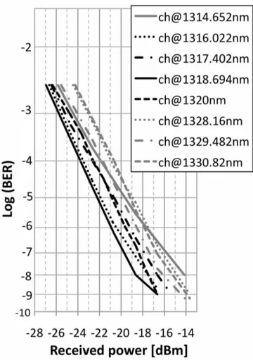
Fig. 7. 10-Gb/s BER curves in back to back for the AWG based transmitter with 10-m drop fiber for various AWG channels: from 1314.652 nm to 1530.82 nm.
10−3 BER, which is below the enhanced FEC limit of 3·10−3 [9], whereas the 1-km cavity both due to the worse back to back performance (around 1 dB penalty) and the transmitter output power, which is 0.7 dB lower, can bridge more than 40-km SSMF. As the OTF based self-tuning trans-mitter is concerned even longer feeder fibers have been bridged thanks to the available output power and better performance. In particular a 5· 10−4BER has been obtained after 72 km of SSMF for the 10-m cavity, while 40-km SSMF can be bridged by the 1-km drop fiber transmitter with BER lower than 3 · 10−3FEC limit.
Previously shown measurements were performed for the OTF centered around the RSOA gain peak and for the AWG channel at 1320 nm. The transmitter performance over the available RSOA gain bandwidth are instead shown in Fig. 7, which presents the back to back BER curves at 10 Gb/s for eight channels of the AWG, covering the spectrum between 1314.652 nm and 1330.82 nm.
The performance refer to the few-meter cavities and, as can be seen, present a 3 dB variation among all the channels. The worst performance are associated with the farthest channels from the RSOA gain peak, bias currents have been optimized channel by channel and range between 107 mA and 137 mA; the optimization has been performed by monitoring the BER at a fixed received power. When higher bias currents are
necessary to make up for a slightly lower roundtrip gain, this also translates in a lower transmitter ER, which actually varies from 4.3 dB for the 1320 nm channel to 2.8 dB for the 1330.82 nm channel and motivates the 3-dB difference among the various channel performance.
IV. CONCLUSION
We have experimentally demonstrated operation at 10 Gb/s of a network-embedded colorless self-tuning WDM transmitter for fronthaul access applications, which exploits self-seeding in an O-band RSOA and allows the ODN fiber plant reuse. Due to the high polarization dependence of the RSOA gain steady performance and a high round-trip gain are obtained thanks to a FRM, located in proximity of the remote-node and shared among all the ONUs and a FR placed at the output of the RSOA. The transmitter performances have been experimentally evaluated for various drop fiber lengths, which characterize the transmitter cavity together with the WDM multiplexer, which has been supplied either by a 32-channel Gaussian Athermal Cyclic AWG or an O-band tunable optical filter. Comparison of measurements in back to back and after propagation over tens of kilometers of SSMF have confirmed the absence of chromatic dispersion penalties, endorsing the choice of moving the device operation in the O-band. Both WDM multiplexers have allowed to bridge more than 40-km SSMF at 10 Gb/s with cavity up to 1 km. Whereas the OBF based transmitter allowed for propagation over 72-km SSMF with BER lower than the 3·10−3 FEC limit. Results have been confirmed over 15 nm on the RSOA gain bandwidth testing various cyclic-AWG channels. These results are encouraging in view of a possible self-tuning transmitter exploitation in the mobile front-haul.
REFERENCES
[1] P. Chanclou, et al., “Optical fiber solution for mobile fronthaul to achieve cloud radio access network,” in Proc. Future Netw. Mobile Summit 2013, Lisbon, Portugal, Jul., pp. 1–11.
[2] E. Wong, K. L. Lee, and T. B. Anderson, “Directly modulated self-seeding reflective semiconductor optical amplifiers as colorless trans-mitters in wavelength division multiplexed passive optical networks,” J. Lightw. Technol., vol. 25, no. 1, pp. 67–74, Jan. 2007.
[3] M. Martinelli, L. Marazzi, P. Parolari, M. Brunero, and G. Gavioli, “Polarization in retracing circuits for WDM-PON,” IEEE Photon. Technol. Lett., vol. 24, no. 14, pp. 1191–1193, Jul. 15, 2012. [4] M. Presi, A. Chiuchiarelli, R. Corsini, and E. Ciaramella, “Self-seeding
of semiconductor lasers for next-generation WDM passive optical net-works,” in Proc. 15th ICTON 2013, Cartagena, Spain, Jun., pp. 1–4, paper We.C3.2.
[5] L. Marazzi, et al., “Up to 10.7-Gb/s high-PDG RSOA-based colorless transmitter for WDM networks,” IEEE Photon. Technol. Lett., vol. 25, no. 7, pp. 637–640, Apr. 1, 2013.
[6] Q. Deniel, et al., “Up to 10 Gbit/s transmission in WDM-PON architecture using external cavity laser based on self-tuning ONU,” in Proc. OFC/NFOEC, Los Angeles, CA, USA, 2012, pp. 1–3, paper JTh2A.55.
[7] L. Marazzi, P. Parolari, R. Brenot, G. de Valicourt, and M. Martinelli, “Network-embedded self-tuning cavity for WDM-PON transmitter,” Opt. Express, vol. 20, no. 4, pp. 3781–3786, 2012.
[8] A. D. McCoy, P. Horak, B. C. Thomsen, M. Ibsen, and D. J. Richardson, “Noise suppression of incoherent light using a gain-saturated SOA: Implications for spectrum-sliced WDM systems,” J. Lightw. Technol., vol. 23, no. 8, pp. 2399–2409, Aug. 2005.
[9] T. Mizuochi, “Next generation FEC for optical communication,” in Proc. OFC/NFOEC, San Diego, CA, USA, 2008, pp. 1–3, paper OTuE5.