different bandwidth or quality of service is required). In this scenario, to provide uninterrupted communication services, ef-ficient intersegment HO capability must be implemented. The architecture considered includes a satellite segment and a num-ber of Wi-Fi hot spots. A mobile node (MN) can switch from a segment to other exploiting services of mobile Internet protocol (MIP). This architecture introduces great flexibility and ensures capillary coverage; it also strongly affects Transmission Control Protocol (TCP)-based application performance. To efficiently face HO consequences, particularly when the TCP runs as a transport protocol, an innovative protocol architecture based on cross-layer (CL) exchange of information is proposed. Analyses of TCP dy-namics during HOs and the performance improvement introduced with the proposed CL architecture, evaluated through the network simulator Ns-2, are presented.
Index Terms—Cross layer (CL), handover (HO), multisegment
networks, Transmission Control Protocol (TCP).
I. INTRODUCTION
N
OWADAYS, broadband access to networks is often re-quired in mobility and over wide and heterogeneous geographical areas. In this context, broadband satellite (SAT) networks allow potentially global coverage and, thus, ubiq-uitous access to the communication services, whereas Wi-Fi systems, in general, offer much higher capacity and less latency but in a limited coverage area. The following technologies, if used jointly, can represent an optimum solution for mobile and nomadic users to uninterruptedly access the Internet: high capacity and low delays under the Wi-Fi “hot-spot” coverage, long-range mobility, and service continuity, where Wi-Fi access is not available, due to SAT links. Of course, efficient interseg-ment handover (HO) procedures are needed to switch between such different technologies.Mobile Internet Protocol (MIP) [1], [2] provides mobility support at the network layer, allowing mobile nodes (MNs) to
Manuscript received December 17, 2007; revised April 24, 2008 and September 14, 2008. First published December 22, 2008; current version published May 29, 2009. The review of this paper was coordinated by Prof. Y. Cheng.
The authors are with the Department of Electronics Engineering, University of Rome “Tor Vergata,” 00133 Rome, Italy (e-mail: luglio@ uniroma2.it; [email protected]; [email protected]; zampognaro@ ing.uniroma2.it).
Color versions of one or more of the figures in this paper are available online at http://ieeexplore.ieee.org.
Digital Object Identifier 10.1109/TVT.2008.2011274
assigned when visiting other networks. When the MN moves to a new location, it obtains and registers a CoA with the HA. A CoA can be, for instance, an IP address belonging to the subnet of the new access router (AR), which is called a foreign agent (FA), to which the MN is connected. Therefore, all the packets directed to the MN are intercepted by the HA, which encapsulates and forwards them to the CoA [3]. The FA then deencapsulates incoming packets and delivers them to the MN. Packets that are generated by the MN instead have the permanent IP and not the CoA as the source so that explicit support for mobility must be present in the routers of the visited networks. Further details are provided in [4].
MIP has been introduced to offer mobility to nomadic users giving a dynamic point of access from different wired networks keeping a unique IP address reference. This concept has been extended to wireless networks, which are more suitable to mobility and more demanding in terms of HO procedures. Nevertheless, in all its realizations, MIP has to deal with the so-called “HO latency” or out-of-service time, and it is not able to mask the impairments of such latency to higher layers. In fact, an MIP HO results in an interruption of the communication at layer 3 (L3) with consequent packet losses. The duration of such an interruption is usually composed of the time to connect the MN to the new link [HO performed at layer 2 (L2)] and the time needed to update routing (HO performed at L3) [5].
Transmission Control Protocol (TCP), i.e., the connection-oriented transport protocol, is particularly affected by the oc-curence of HO. In fact, in addition to the HO latency time, the HO between links with different delays and bandwidth-delay products (BDPs) can cause a number of problems such as the generation of segment bursts and the delivery of out-of-order packets [6]. In fact, the following can occur.
1) The TCP misinterprets any loss during HOs as a conges-tion signal, thus dropping its congesconges-tion window [7] and, as a consequence, the transmission rate.
2) The TCP computes the retransmission timeout (RTO) on the basis of measured round-trip time (RTT) values; then, a sudden significant variation of the RTT after an HO can lead to two undesired dynamics: 1) If the new link has a larger RTT, the RTO can prematurely expire, with a consequent reduction of the congestion window to a minimum value, even without losses, and 2) if the new link has a shorter RTT, a too-long time (equal to the old
RTO) must elapse before the TCP sender can recover from a packet loss [8].
3) After the HO procedure is completed, the new link is established; however, TCP state variables, which regulate the transmission rate, are either still tailored for the old link or dropped after loss detection, and a long time may be required before retrieving the optimum settings. In this paper, Mobile IPv6 (MIPv6) [9] is considered. It leverages on newer IPv6 features that are suitable for mobility. For instance, the setup of ad hoc FAs is avoided, and route optimization is based on the direct communication between the MN and its correspondent node (CN). However, this does not prevent experiencing the HO latency. The scope of this paper is to address TCP inefficiency and define a cross-layer (CL) algorithm to mitigate impairments when an HO occurs.
This paper is organized as follows. Section II reports on related work. Section III illustrates the reference scenario. Section IV describes the proposed CL architecture and the mechanism designed to optimize TCP performance during HOs. Section V describes the simulation setup and offers com-ments on the results achieved through the network simulator Ns-2 [10]. Finally, Section VI provides conclusions.
II. RELATEDWORK
In the literature, a number of schemes have been proposed to implement a seamless HO, taking into account TCP features. Most of them aim to reduce both the interruption period and the packet loss during HOs, whereas some focus particularly on TCP modifications in combination with lower layer modi-fications to allow ongoing connections to preserve their long-term throughput during HOs. Part of these schemes use CL mechanisms to reach this scope.
Internet Engineering Task Force (IETF) Internet drafts HAWAII [11] and Cellular IP [12] propose enhancements ad-dressed to intradomain micromobility to reduce the number of hops that are necessary for the mobility update messages and, thus, the HO latency perceived by upper layers. The same goal is reached by some hierarchical mobility schemes [13], [14]. Basically, the MN exchanges negotiation messages with the HA only if it changes a domain, while an intradomain HO is handled locally. However, interdomain macromobility is still managed by the MIP, leaving unaltered effects experienced at the upper layers.
In [15] and [16], buffering schemes at the FA are proposed to avoid packet loss due to HOs. During HO execution, the current FA temporary buffers packets instead of sending them to the MN (or, in the alternative, the FA sends packets through the current link and temporarily buffers them to ensure that the packets are not lost during HOs). When an HO is performed, the current FA forwards buffered data packets to the new FA. A mechanism to eliminate duplicated packets is implemented in the FA (details are provided in [16]). Nevertheless, depending on the time needed to find and register to a new FA, buffer overflows may occur. Moreover, the additional buffering time can be interpreted as an explicit congestion signal by the TCP, leading to a throughput reduction (which is a consequence of timeout expiration). El Malki [17] and Zhu and McNair [18]
propose HO schemes based on link-layer triggers toward the MIP. Due to a CL architecture, the link layer is able to provide various link status information to the MIP module. This way, it is possible to make routing changes faster (known as the L3 movement [9]) and to perform an IP preregistration to the new FA (before performing the HO at the link layer). During both movement detection and L3 preregistration phases, data packets are sent/received through the old FA. Such an approach has a criticality in the correct anticipation of the HO event to trigger the preregistration procedure.
Some approaches are focused on counteracting the impact of HOs using modified TCP implementations [19], [20]. In [19], a TCP variant, which is named the Freeze-TCP, is proposed. It forces an interruption of the TCP flow to avoid packet loss dur-ing HOs by advertisdur-ing a zero window (ZW). This allows stop-ping transmission without dropstop-ping the TCP congestion window. Afterward, the TCP sender sends “probe” packets to solicit a non-ZW ACK, which retrieves transmission with the un-changed congestion window. This mechanism implies that the link layer properly notifies an HO occurrence to the transport layer. Neither timing nor signaling for such link-layer notifica-tions is defined in detail. Furthermore, Freeze-TCP addresses only the case where the MN acts as a TCP receiver. Last but not the least, if the “probe” packet is lost, its retransmission is exponentially backed off, and a substantial idle time can elapse before restarting the TCP transfer after the reconnection. To reduce this idle time, [20] proposes a scheme aiming at reestab-lishing TCP transfer as soon as connectivity is again available with the new link. In brief, after a reconnection, the TCP receiver sends three copies of the last received ACK, triggering the TCP sender to enter the TCP fast-retransmit–fast-recovery (FR-FR) mechanism [8]. This approach leads to the advantage of reducing the overall HO latency. On the other hand, after running FR-FR, the effective transmission rate is halved.
Another approach is oriented to identify the best tradeoff be-tween the reduction of the HO duration and the minimization of the network/node changes. It involves both link- and transport-layer customizations via a CL architecture [21]. Message ex-change and slight TCP modifications are used to better handle HOs, but through only a theoretical approach (no simulation activity).
Another example of a CL-enabled HO using the MIP in a wireless scenario is proposed in [22]. Singh and Iyer use simple information coming from the network layer (connect, disconnect) to drive a customized TCP, which is called the Adapted-TCP (ATCP), during the handoff phase. The ATCP runs only at the MN and, after a disconnection and a connection notification, appropriately handles internal TCP parameters to allow a fast restart of the TCP transfer after HOs. Optimization of TCP data transfer is provided for both directions between the MN and the CN. On the other hand, the ATCP does not prevent packet/ACK losses during HOs, and when a disconnection occurs, if the sending window is closed and the RTO is larger than the HO latency, the ATCP sender must wait for an RTO expiration before restarting TCP transfer after a reconnection [22]. In addition, the adaptation of TCP state variables after a reconnection is not optimized for scenarios in which the HO is performed among links with different characteristics
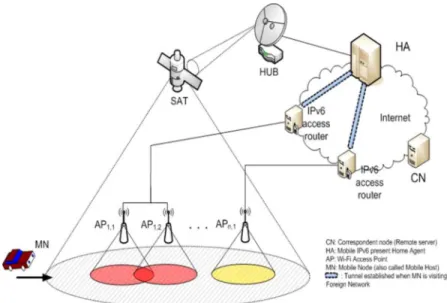
Fig. 1. Mobile environment.
(i.e., different BDPs). The ATCP considers the value of the state variables that is achieved before the disconnection as the optimum value also over the new link. The assumption does not apply in the event of switching among links with quite different BDPs.
In [23], some guidelines for TCP performance improvement during HOs are presented; however, it is a preliminary study not describing in detail the scenario and the HO procedures. The scheme proposed in this paper is mainly the development and the enhancement of the idea presented in [23]. The actions performed before and after HOs are partially inspired by the work in [19] and [22], but differently, their main targets are
1) to completely avoid losses during an HO through a CL architecture based on [21];
2) to optimize the performance of TCP-based applications when an HO occurs between links with quite different BDPs.
To this scope, CL signaling involving transport, network, and link layers has been designed. Compliant to the ECLAIR architecture [21], an “optimization subsystem” (OSS) manages CL signaling, whereas “tuning layers” (TLs) interact with each protocol layer to drive optimized actions.
Throughout this paper, the performance of the proposed CL scheme is mainly expressed using the standard TCP [7], [8] as a benchmark, and a comparison with the ATCP is also provided.
III. REFERENCESCENARIO
In the reference scenario, with key elements shown in Fig. 1, an MN, which represents the user terminal, moves across a hybrid network composed of
1) one GEO SAT segment, which, due to the wide coverage, reaches the MN in all its service area;
2) n independent wireless LANs (Wi-Fis) scattered (even partially overlapped) into the above-defined SAT cover-age area and identified by access points (APs).
For the generic APij, the index i identifies its subnet,
man-aged by the same operator and with a given IP address space,
and the index j represents the multiplicity of APs that are interconnected to form the network i. As a term of reference, the SAT technology adopts the Digital Video Broadcasting - Return Channel on Satellite (DVB-RCS) mobile standard [24], [25], Wi-Fi adopts the IEEE 802.11b standard [26], the MIPv6 [9] standard is considered, and the TCP is adopted as the transport-layer protocol.
During TCP connection life, one or more HOs occur as a consequence of user mobility. For instance, if the session is started while the MN is connected via the SAT channel, during MN motion, Wi-Fi coverage might become available. Since Wi-Fi networks usually provide higher bandwidth and are characterized by a lower propagation delay with respect to SAT networks, switching from SAT to a Wi-Fi AP may be convenient to improve the TCP performance.
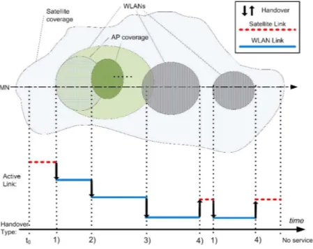
Fig. 2 pictorially shows the simplified mobility reference scenario in which the MN moves along a straight line. Every possible HO occurrence is identified with a vertical arrow, with the MN under SAT coverage since t0 and performing an HO
whenever a Wi-Fi connection becomes available. The speed of the MN determines the time spent under the Wi-Fi coverage. In this paper, only HOs implying MIP services with out-of-service time due to the execution of HO and MIP procedures are considered.
In Fig. 2, cases 1 and 4 represent an L3 HO between heterogeneous link technologies. In those cases, it is possible to use the MIP standard CoA technique to perform this HO; however, the side effects due to the physical link differences must be considered to optimize the TCP/IP stack behavior.
In case 2, the switch occurs between two APs of the same Wi-Fi network. Like what strictly happens in an L2 HO in-side the Wi-Fi, only the link layer and the physical layer are involved.
Case 3 needs an L3 HO because the HO involves two different Wi-Fi subnets. In this case, since the MN changes the network in use, it must obtain a new IP address using MIP func-tionalities. Since this paper is oriented to HOs where the source and destination networks have different characteristics, cases 2
Fig. 2. Possible scenario HOs.
and 3 are not addressed specifically, although, in principle, the proposed CL HO model is applicable.
A. MIPv6 HO Process
MIPv6 allows the MN to change networks without explicitly interrupting upper layer sessions. This process requires a set of operations, initiated by the MN, that cause the loss of IP con-nectivity for a time period, known as the “HO latency.” Then, although the movement of the MN is completely transparent to higher layer protocols, there is a time interval during which the MN can neither send nor receive packets. Initially, the MN leads the HO process with the movement detection. In the considered scenario, the IP network interface of the MN is always active and is connected to either SAT or Wi-Fi radio modules. In this paper, the MN is assumed to have duplicated hardware, where two link layers (Wi-Fi and SAT) can be active simultaneously. This assumption is consistent with the fact that since each segment of the network under study requires a specific RF front end, the MN must be equipped with multiple RF components. Such connectivity overlay or temporary macrodiversity does not imply duplicated packet delivery [15], [16] but can support motion detection and deliver appropriate triggers to the MIP HO procedures once the CL mechanisms have been enforced. When the MN is attached to the Wi-Fi link, the SAT radio module could also be turned off for power-saving or heat-related issues.
In the reference scenario, the MN is assumed to move in open areas so that it is always within the SAT coverage and, in certain intervals, also under the Wi-Fi coverage. In such conditions, the MN can realize its movement through either the availability/unavailability of the Wi-Fi link or the variation of some link parameters (i.e., the bit error rate and the SNR). The HO process is initialized in the following cases.
1) The MN is connected to the SAT network (for example, the home network) and receives the notification that a Wi-Fi link is available.
2) The MN is connected to a Wi-Fi network (for example, a foreign network) and receives information that the link quality is degrading.
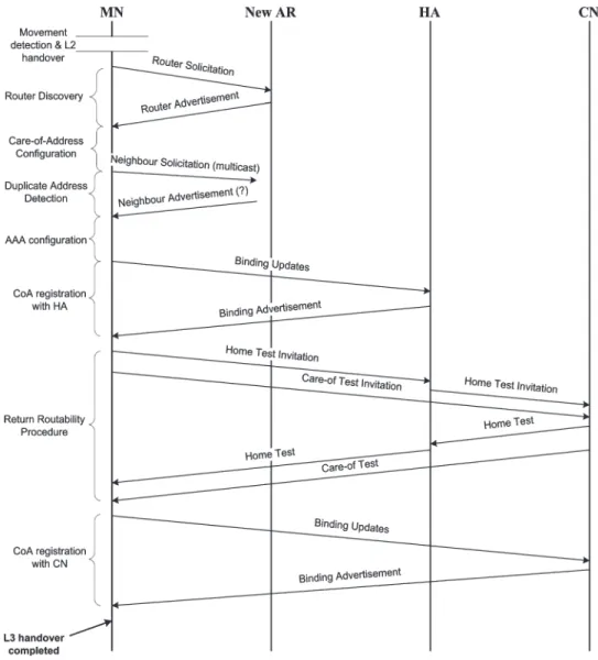
Once the MN has left the old network, the new AR is found through the reception of a “router advertisement” message (“mobile prefix advertisement” in MIPv6), which is either periodically broadcast by the AR itself or issued in response to a “router solicitation” message that is explicitly sent by the MN. The time needed for router discovery depends on which of the two methods is applied. Afterward, the MN updates its network configuration with an IPv6 address of the new network: the new CoA. In addition, the MN must perform duplicate address detection to check that the CoA that is as-signed in the configuration phase is unique on the link. If the MN moves across different administrative domains (SAT and Wi-Fi are most likely managed by different service providers), an authentication, authorization, and accounting (AAA) server will require the negotiation of MN credentials before allowing access to the new network.
Once the MN has successfully accessed the new network, it must inform the HA of its new location. The MN registers the CoA by sending a binding update (BU) to the HA, which acknowledges the correct reception of the BU by replying with a binding acknowledgement (BA). Then, the HA is able to tunnel packets that are bound to the MN to the CoA.
According to MIPv6, the MN sends a BU to all its CNs to allow routing optimization. With respect to registration with the HA, another procedure, which is known as “return routability” (RR), is performed before the BA/BU exchange between the MN and each CN. RR is used to assure the CN that the BU is authentic and not from a malicious attacker. Briefly, RR
Fig. 3. IPv6 HO procedure.
consists of a home test and a care-of test. The CN issues the two tests to the MN via the HA and the route-optimized path, respectively.
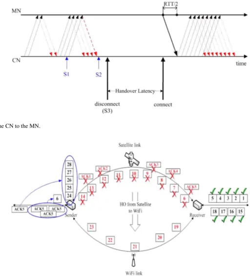
Fig. 3 shows the sequence of operations/messages foreseen in the IPv6 HO. The overall “HO latency” depends on a particular communication scenario: the propagation RTT of the network, the traffic load, the AAA requirements, etc. With reference to the signaling exchange drawn in Fig. 3, the simulations proposed in Section V consider a minimum value for the “HO latency” that is equal to five times the RTT of the network to which the MN is moving.
IV. CL ARCHITECTURE FOREFFICIENTMANAGEMENT OF AHOAT THETRANSPORTLAYER
In wireless networks, the traditional Open Systems Intercon-nection stack might not perform at its best [27]–[31] due, for instance, to the variability of the channel conditions. When applicable, the traditional layered structure can be modified, allowing the different layers to exchange information, to make each layer aware of the events handled at different layers and then to adapt its behavior according to the global status of the protocol stack. This approach is called the CL.
In this context, we aim to identify a CL architecture for MNs that is able to efficiently manage HO events. In particular, CL interactions among three protocol layers (link, network, and transport) are exploited to inform in advance the TCP of an impeding HO and trigger appropriated actions on the internal TCP variables to avoid packet/ACK losses during HO operations and maximize performance when reconnecting over the new link. To achieve these goals, CL signaling must be scheduled accurately, and particular actions must be performed, depending on the TCP transfer direction and the characteristics of the new link. Then, a centralized subsystem is needed to handle multiple CL interactions and to trigger the most proper actions on a case-by-case basis. In addition, particular inter-faces between protocol layers and the centralized subsystem must be designed with the aim of minimizing changes in the MN protocol stack.
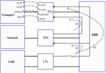
The CL architecture defined in [21] and named ECLAIR well matches with the above requirements. The ECLAIR main com-ponents are the OSS and the TLs. The OSS includes protocol optimizers that manage CL interactions. The OSS interacts with the existing protocol stack through the TLs.
To counteract impairments at the transport layer (adopting the TCP) that are caused by HOs, we propose a CL architecture
based on ECLAIR, in which the following kinds of CL signal-ing are enabled.
1) From link-to-transport layer (s1). On the basis of the L2 status, the link TL (LTL) can generate two trigger signals: If the MN is connected to Wi-Fi, the signal trigger can be generated as soon as the SNR over the Wi-Fi link degrades under a preselected threshold. If the MN is connected to the SAT link, the signal trigger can notify that a new Wi-Fi network is in the range of the MN. The OSS delivers L2 triggers to the transport TL (TTL); this signal is used to “prepare” the TCP for the forthcoming HO event. In fact, the L2 HO is, in general, unpredictable by upper layers and leads to the loss of the outgoing/incoming packets. The goal is to stop the TCP transmission opportunely before the L2 HO to prevent packet losses.
2) From link-to-network layer (s2). When the new link is available to be accessed, the LTL generates an L2 trig-ger to advertise the L2 HO. This trigtrig-ger is sent to the network TL (NTL) and indicates that HO procedures can start.
3) From network-to-transport layer (s3). The NTL, when receiving an L2 trigger, sends a disconnection signal to the TTL to announce the disconnection. In addition, when the HO is completed, and the new link connection is established, the NTL sends to the TTL a connection signal. Both connection and disconnection signals are then used by the TTL to make proper adjustments to the TCP status variables.
The proposed CL architecture is depicted in Fig. 4. All the triggers are managed by a centralized OSS, which allows CL communication between the link and network layers. Schedul-ing of CL signals (s1, s2, and s3) plays an important role in achieving optimized performance. In particular, the interval time between s1 and s3 must be adjusted to allow the TTL and the TCP to perform all the appropriated actions before disconnection (see the next sections for details). This interval time depends on a number of factors, for instance, the RTT in the current link, current channel characteristics correlated with the MN speed, and the communication direction. In this paper, we assume that the OSS is able to calculate the optimum interval time, which means that disconnection is performed just after the end of TCP CL operations that are aimed to temporarily stop the transfer: no packet/ACK losses while TCP idle time is minimized. In general, it is preferred to slightly overestimate this interval time to avoid losses. TCP modifica-tions that are triggered by CL signaling are different for the two communication directions.
Due to standard TCP dynamics (Fig. 5), when the “old” link is disconnected, a certain number of sent packets/ACKs will be dropped, and the RTO is initialized with reference to the first unacknowledged packet. Depending on the “HO latency,” one or more RTO expirations and consequent retransmissions can occur. When the MN is reconnected to the new link, the TCP sender might not yet be able to restart the transmission since the RTO has not yet expired. In this way, the “HO latency” is fur-ther increased, and, consequentially, the performance perceived
Fig. 4. CL architecture—Ns-2.
at the upper layer is worse. At the end, transmission restarts with cwnd set to 1 and ssthresh halved as many times as the number of RTO expirations.
To cope with these problems, we propose the following actions on TCP variables/algorithms that are driven by the TTL.
A. TCP Transfer From the MN to the CN
When the TTL receives an L2 trigger (s1), the MN, acting as the TCP sender, will freeze its transmission. Specifically, the cwnd value is decreased by one for every received ACK: The left edge of cwnd is properly moved to the right [8], whereas the right edge is kept unchanged. In this way, when all the ACKs “in flight” are received, cwnd results are equal to 0. The rationale is to prevent, as much as possible, sending a large number of packets that will probably be lost due to the forthcoming HO event.
Therefore, after the disconnection signal is received (s3), two different situations can occur.
1) The left edge of cwnd reaches the right edge, which means that the time elapsed between an L2 trigger and a disconnection signal was long enough to receive all the ACKs that are still in flight.
2) cwnd is open, which means that there are still edged data; the RTO is initialized to the first unacknowl-edged byte.
In the latter case, the TTL forces the suppression of the RTO to prevent its expiration (and consequent retransmissions) during the HO period. Furthermore, cwnd is closed, setting left and right edges to the last acknowledged byte. In practice, although the interval time between s1 and s3 is not enough to close cwnd, the TTL “hides” possible losses to the TCP. Finally, when the TTL receives the connection signal, cwnd is set to 1 (the immediate transmission of a packet is allowed), and ssthresh is set equal to the pipe size of the new link. In this way, the TCP is able to reach the optimum window size with an exponential growth (a slow-start algorithm [8]). The general scheme of the proposed enhancement, based on the use of CL signaling, is depicted in Fig. 6.
Fig. 5. TCP standard behavior in case of disconnection.
Fig. 6. TCP CL from the MN to the CN.
B. TCP Transfer From the CN to the MN
With the CL capability being implemented only in the MN, in case of transfer from the CN to the MN, TCP enhancements, which are triggered to cope with HOs, concern the TCP re-ceiver. When the L2 trigger is received, the TTL forces the TCP receiver to notify a ZW by setting the “advertise window” field in the ACK packets to zero. To this aim, the LTL and the NTL must be properly set to produce L2 triggers at least an RTT before the L3 disconnection. Since the reception of the L2 trigger, the TTL delays the transmission of the last ACK, sending it after the reception of a further packet or after the reception of the connection signal to reopen the TCP window advertising a full window [8] that is tailored to the new link characteristics. Fig. 7 shows the TCP dynamics due to the application of the proposed CL architecture based on the use of CL signaling.
V. SIMULATION
A. Description of Ns-2 Setup
To evaluate the performance of the TCP with the proposed enhancements in comparison with the standard protocol stack performance, an Ns-2 simulation has been set up. In particular, a new TCP CL module has been added to the simulator. The baseline simulation script simulates a data transfer according to the scenario described in Section III, assuming a SAT channel
of 1 Mbit/s with the RTT fixed to 500 ms, and a Wi-Fi “hot-spot” area with a bandwidth of 2 Mbit/s and an RTT delay of 20 ms. The data packet dimension is fixed to 1460 Bytes. The number of transferred bytes and the throughput during the HO are used as metrics to evaluate performance. The selected application is the FTP, which runs in both communication directions, that is, from the MN to the CN and vice versa.
At the beginning of the FTP session, the MN is connected to a Wi-Fi AP. During the transfer, three HO events occur.
1) The MN moves from Wi-Fi to SAT after 10 s.
2) The MN switches to a new Wi-Fi AP after 20 s from event 1.
3) The MN connects again to the SAT link until the end of the simulation after 15 s from event 2.
In the case of a CL-modified stack, one RTT (of the current link) before an HO, the L2 trigger is generated, followed by the proper CL procedures. The data transfer simulation has been repeated, varying the HO latency in a range from 0.1 s (five times the Wi-Fi link RTT) up to 5 s for the SAT-originated HO. In the case of the Wi-Fi-originated HO, latency starts at 2.5 s (five times the Wi-Fi link RTT). In fact, as presented in Section III-A, the HO disconnection lasts at least five RTTs of the destination network, which is needed to complete the HO procedure (see Fig. 3). The FTP data transfer uses the TCP standard New Reno with and without CL actions optimized, as described in Section VI, according to whether MN-to-CN or CN-to-MN direction is considered.
Fig. 7. TCP CL from the CN to the MN.
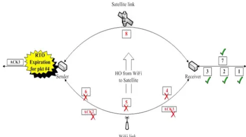
Fig. 8. Main TCP dynamics during the HO from SAT to Wi-Fi.
B. Conceptual Iteration of the TCP During the HO
Different from all the previous works on this topic (see Section II), this paper addresses HOs between links with a quite different BDP. The BDP is a very important factor in a window-based protocol such as the TCP because it determines the amount of data that can be in transit in the network. Specif-ically, both TCP cwnd and ssthresh are dynamically changed on the basis of the sender estimate of the BDP (through RTT measurements).
Since BDPsat (the BDP of a SAT link) is generally much
larger than BDPWi-Fi(the BDP of a Wi-Fi link), two different
problems can be experienced when an HO occurs.
1) Moving from SAT to Wi-Fi, if cwnd and/or ssthresh are set to values that are higher than BDPWi-Fi, the number
of packets injected by the transport layer leads to MN buffer overflow, increasing the experienced latency (from application), with the possibility of dropping a large amount of packets, triggering TCP timeouts.
2) Moving from Wi-Fi to SAT, if both cwnd and ssthresh are set to values that are much lower than BDPsat (also
considering a possible timeout expiration due to “HO latency”), since the TCP enters in the congestion avoid-ance phase (linear cwnd increase on an RTT basis) when
cwnd is far away from BDPsat, the increase of cwnd
up to the optimum value requires a long time, resulting in the temporary significant underutilization of the SAT resources.
Figs. 8 and 9 provide a general description of what can happen during the HO from the TCP point of view. To simplify the modeling, the HO latency is assumed to be the minimum (see Section III-A), the TCP congestion window (cwnd) does not refer to any particular value, but is simply indicative of the pipe size of the old link, and packet numbering concerns only packets that are involved in the HO. All the effects will be separately treated in the next sections. In the case depicted in Fig. 8, the TCP sender initially transmits over SAT links. Due to the large BDP, many packets are “in flight” at any time. The HO occurs just after packet 5 is received correctly. Thus, all the packets from 6 to 14, as well as ACKs from 1 to 5, are lost due to the old link disconnection. After HO execution, the sender continues the packet transmission, as long as the cwnd value is not reached, over the new Wi-Fi link. The reception of packets over the new link triggers duplicated ACKs concerning the last packet that is received in sequence, i.e., ACK5. The first ACK5 acknowledges five packets since ACKs 1–5 were lost in the old link. As a consequence, a burst of five packets (from 24 to 28) is
Fig. 9. Main TCP dynamics during the HO from Wi-Fi to SAT.
delivered to the sender queue waiting for transmission over the Wi-Fi link. In addition, the successive three duplicated ACKs lead to the retransmission of packet 6 by starting the TCP error recovery procedures that, considering the high number of lost packets, most likely are concluded with an RTO expiration.
Fig. 9 concerns the HO from a Wi-Fi to a SAT link. With respect to the previous case, the number of packets that are initially in flight over the Wi-Fi link is much lower. Therefore, when the HO occurs, only three packets (4–6) and two ACKs (2 and 3) are lost.
Furthermore, once the SAT link is available, only a few packets can be transmitted due to the low value of cwnd. In the example, only packet 7 is sent. Its reception triggers the duplicated ACK of the last packet that is received in sequence, i.e., ACK3. Due to the smaller cwnd and the large RTT of the new link (SAT), an RTO expiration before the reception of three duplicated ACKs is very likely. In the example, the RTO relative to packet 4 expires just after the reception of the first dupli-cated ACK.
C. Performance Evaluation
The first simulation, which is aimed to evaluate performance in terms of throughput, concerns the MN sending data to a CN with HO latency THO= 4 s. Fig. 10 shows, for this case, the
instantaneous throughput that is achieved over time during the data transfer by the standard and the CL-enabled stack. The throughput difference of these two cases has also been plotted.
The gain in terms of throughput, which is defined as the difference of the throughputs of the two cases, shows a sig-nificant improvement in performance, particularly after the disconnect event. The gain is slightly negative just after the L2 trigger event, clearly due to the anticipatory CL actions, which prepare the HO event with a reduction of packets in flight. This temporary loss is compensated by the CL stack behavior after the disconnect event. In fact, the throughput gain using the CL approach overcomes 0.5 Mbit/s for several seconds after all the HO events. Performance improvements can be evaluated in terms of additional bytes that are transmitted with the proposed scheme with respect to the TCP standard stack in
Fig. 10. Instantaneous throughput from the MN to the CN.
the time interval from the reception of the L2 triggers before disconnection to the achievement of the maximum throughput over the new link when considering the standard stack (referred to as “transferred byte gain”):
1) (Wi-Fi→ SAT) 1.08 MBytes; 2) (SAT→ Wi-Fi) 0.4 MBytes; 3) (Wi-Fi→ SAT) 1.4 MBytes.
In particular, at 10 + THO s, 30 + THO s, and 45 + THO s,
with the proposed CL handling of cwnd and ssthresh values, it is possible to force the TCP to reapply the slow-start algorithm and obtain a faster growth of the data rate up to the BDP of the new link. Harmful timeouts are also avoided in the CL case. Finally, freezing the TCP data flow, it is also possible to avoid the additional initial delay caused by the data stored in the internal queues during the HO that must be sent when the new channel becomes available.
The second simulation concerns the data transfer from the CN to the MN, with HO latency THO= 4 s as in the previous
simulation. Fig. 11 shows the instantaneous throughput. The performance is similar to that of the previous case with the following values for the transferred byte gain:
1) (Wi-Fi→ SAT) 1.1 MBytes; 2) (SAT→ Wi-Fi) 0.48 MBytes; 3) (Wi-Fi→ SAT) 1.46 MBytes.
Fig. 11. Instantaneous throughput from the CN to the MN.
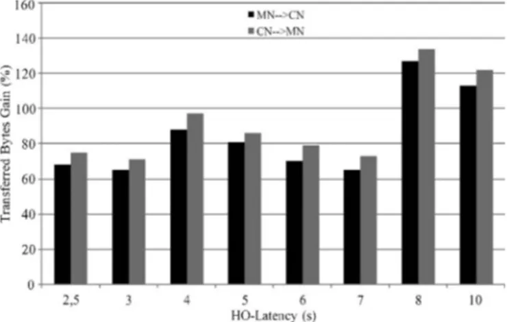
Fig. 12. Transfer gain as a function of the HO latency: Wi-Fi→ SAT.
Fig. 13. Transfer gain as a function of the HO latency: SAT→ Wi-Fi.
To have an exhaustive view of the performance gain of the CL scheme in comparison with the standard TCP, the trans-ferred byte gain during Wi-Fi→ SAT and SAT → Wi-Fi HOs has been calculated through several simulations as a function of different THO. The achieved results have been reported in
Figs. 12 and 13, each showing the transferred byte gain in terms of the percentage for both traffic directions. In Fig. 12, the HO occurs from Wi-Fi to SAT and has a THOduration variable from
2.5 up to 5 s.
This relatively high minimum value is consistent with the slower registration procedures of the SAT connection
(see Section III-A). The proposed scheme allows increasing the transmitted bytes during the HO from about 65% to 130%. Variations mainly depend on the time elapsing between the reconnection signal (restart of the CL scheme transmission after the HO) and the RTO expiration (restart of the standard protocol stack transmission after the HO). Then, the larger this interval time is, the higher the improvement coming from CL stack adoption will be.
Fig. 13 refers to the HO occurring from SAT to Wi-Fi with a THO duration variable from 0.1 up to 5 s. Since MIPv6
procedures are performed over the Wi-Fi link, the HO latency is shorter than the one experienced in the previous case. The result trend corresponds to the one shown in Fig. 12, whereas the overall improvement is higher (it varies from 110% to 290%).
The rationale relies on two main factors.
1) The RTO is larger since the MN is moving from the SAT network; then, with the standard stack, a larger time elapses before restarting the transmission after the reconnection to Wi-Fi.
2) Since the BDP of the new link is smaller, the CL scheme reaches the maximum throughput much earlier; there is a longer interval time in which standard stack transmission is not yet restarted, and the CL scheme allows transmis-sion at the maximum rate.
Finally, in both HO cases, CN-to-MN transfers over the CL scheme experience a gain that is slightly higher than those from the ones running in the opposite direction. In fact, transmission restarts from the latest cwnd value before the HO, which is usually higher than the Wi-Fi BDP. Definitively, transmission most likely restarts at the maximum rate, whereas in the MN-to-CN case, cwnd is reset to 1 as in Slow Start.
Another set of simulations envisages the same configurations as in Figs. 12 and 13, with the addition of corrupted bits due to channel impairments, resulting in a nonnull packet error rate (PER). File transfer altogether lasts 100 s, whereas the HO event occurs at 50 s. Without loss of generality, the HO latency is chosen to be equal to 4 s for all the considered cases, while three different PER values have been considered: 10−4, 10−3, and 10−2. The results are presented in Figs. 14 (the HO from Wi-Fi to SAT) and 15 (the HO from SAT to Wi-Fi) and expressed in terms of the transferred byte gain achieved with the CL scheme with respect to the standard stack over the entire simulation. Assuming symmetric links, the standard stack leads to identical performance in both transfer directions: from the MN to the CN and vice versa. Therefore, in Figs. 14 and 15, the only line referred to is “Standard.” In general, the results confirm the outcomes of previous simulations while extending their validity to the case where the PER is significant.
The last set of simulations aimed to compare the performance of the CL scheme and that of the transport protocol presented in [22], which is named the ATCP, and is used as a baseline to design the TCP modifications in the proposed scheme. In particular, when the MN acts as a receiver, the proposed scheme and the ATCP advertize a ZW to the sender when disconnection occurs and a full window when a reconnection signal is received. Only the scheduling that is used to perform such actions is slightly different. Instead, in case the MN acts
Fig. 14. Transfer byte gain versus the PER: HO from Wi-Fi to SAT.
Fig. 15. Transfer byte gain versus the PER: HO from SAT to Wi-Fi.
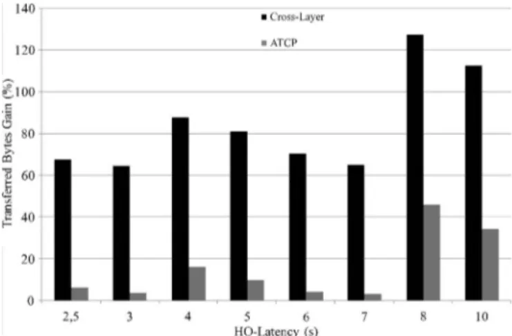
as a sender, the proposed scheme is tailored to support the HOs between links with different BDPs (see Section IV), whereas the ATCP assumes the HOs among similar links. Then, with the same simulation setup that is used for tests resumed in Figs. 12 and 13, the ATCP transferred byte gain (in percentage) with respect to the standard TCP is compared with that already shown relative to the proposed CL scheme for the case where the transfer is from the MN to the CN.
Simulation results are collected in Figs. 16 and 17, showing how the CL scheme outperforms the ATCP and demonstrating the importance of CL adaptation in supporting HOs.
D. Remarks
Simulation results demonstrate the suitability of the pro-posed CL architecture to address HOs between links having quite different physical characteristics. Performance benefits are considerable over all the considered study cases ranging from 65% to 290% with respect to the standard TCP. The key elements in the design are both the prevention of packet losses due to the sudden L2 disconnection and the knowledge of the physical characteristics of the new link. These issues particularly concern the scenario herein addressed, whereas all the other solutions proposed in the literature to face up HO events (see Section II) focus on the scenarios where the HO is performed within networks based on the same technology or
Fig. 16. ATCP performance comparison: Wi-Fi → SAT, from the MN to the CN.
Fig. 17. ATCP performance comparison: SAT→ Wi-Fi, from the MN to the CN.
at least with similar BDPs. In addition, losses that the L2 HO may cause are usually considered negligible, whereas in the considered scenario, they play a relevant role in the achieved performance since they involve different RF components.
Definitively, the proposed CL adaptation is well suited for all the cases where the HO involves networks with different L2 technologies and physical characteristics. In the cases where the aforementioned issues are absent or negligible, performance improvements might be marginal to justify the adoption of a CL architecture. However, such an analysis is out of the scope of this paper.
VI. CONCLUSION
Intersegment HO mechanisms have been addressed in a scenario that is characterized by heterogeneous networks com-posed of a SAT segment and terrestrial wireless segments (Wi-Fi). Deep analysis of the behavior of the TCP during the HO between heterogeneous links has been performed, taking into account the MIP implementation that can lead to packet loss and delays during the HO procedure. Some enhancements based on CL signaling aimed at the mitigation of such problems for TCP file transfers have been proposed, introducing some
adaptations to the parameters and the algorithms of the TCP during the HO phase for both data traffic directions.
The TCP behavior during HOs and the effectiveness of the CL approach have been evaluated through simulations per-formed in Ns-2. The proposed scheme greatly outperforms the standard TCP in all the evaluated cases. A significant performance improvement has been observed when the MN acts as a TCP sender also with respect to the ATCP, which is a protocol that is optimized to manage the HO among links with a similar BDP.
Future work will concern a prototype implementation of the proposed CL scheme to perform real trials.
REFERENCES
[1] C. Perkins, IP Mobility Support, Oct. 1996. RFC 2002. [2] C. Perkins, IP Mobility Support for IPv4, Aug. 2002. RFC 3344. [3] C. Perkins, IP Encapsulation Within IP, Oct. 1996. RFC 2003.
[4] C. Perkins, “Mobile IP,” IEEE Commun. Mag., vol. 35, no. 5, pp. 84–99, May 1997.
[5] X. P. Costa, R. Schmitz, H. Hartenstein, and M. Liebsch, “A MIPv6, FMIPv6 and HMIPv6 handover latency study: Analytical approach,” in
Proc. IST Mobile Wireless Telecommun., Jun. 2002, pp. 100–105.
[6] W. Hansmann and M. Frank, “On things to happen during a TCP hand-over,” in Proc. 28th Annu. IEEE Int. Conf. LCN, 2003, pp. 109–118. [7] W. Stevens, TCP Congestion Control, Apr. 1999. IETF RFC 2581. [8] W. Stevens, TCP/IP Illustrated, vol. 1. Reading, MA: Addison-Wesley,
1994.
[9] D. Johnson, C. Perkins, and J. Arkko, Mobility Support for IPv6, Jun. 2004. RFC 3775.
[10] The Network Simulator NS-2. [Online]. Available: http://www.isi.edu/ nsnam/ns/
[11] R. Ramjee, T. La Porta, S. Thuel, K. Varadhan, and L. Salgareli, IP
Micro-Mobility Support Using HAWAII, Jun. 1999. IETF Internet Draft.
[12] A. T. Campbell, J. Gomez, C.-Y. Wan, S. Kim, Z. Turanyi, and A. Valko,
Cellular IP, Jun. 1999. IETF Internet Draft.
[13] E. Gustafsson, A. Jonsson, and C. Perkins, Mobile IP Regional
Registration, Mar. 2001. IETF Internet Draft.
[14] S. Das, A. Misra, and P. Agrawal, “TeleMIP: Telecommunication-enhanced mobile IP architecture for fast intra-domain mobility,” IEEE
Pers. Commun., vol. 7, no. 4, pp. 50–58, Aug. 2000.
[15] D. Johnson and C. Perkins, Route Optimization in Mobile IP, Feb. 1999. Internet Draft.
[16] C. Perkins and K. Y. Wang, “Optimized smooth handoffs in mobile IP,” in
Proc. 4th IEEE Symp. Syst. Commun., Jun. 1999, pp. 340–346.
[17] K. El Malki, Low-Latency Handoffs in Mobile IPv4, Jun. 2004. Internet Draft.
[18] F. Zhu and J. McNair, “Cross layer design for mobile IP handoff,” in Proc.
VTC—Spring, Jun. 2005, vol. 4, pp. 2255–2259.
[19] T. Goff, J. Moronski, D. S. Phatak, and V. Gupta, “Freeze-TCP: A true end-to-end TCP enhancement mechanism for mobile environments,” in
Proc. INFOCOM, Tel Aviv, Israel, 2000, pp. 1537–1545.
[20] R. Caceres and L. Iftode, “Improving the performance of reliable trans-port protocols in mobile computing environments,” IEEE J. Sel. Areas
Commun.—Special Issue Mobile Comput. Netw., vol. 13, no. 5, pp. 850–
857, Jun. 1995.
[21] V. T. Raisinghani and S. Iyer, “ECLAIR: An efficient cross layer archi-tecture for wireless protocol stacks,” in Proc. WWC, San Francisco, CA, May 2004.
[22] A.-K. Singh and S. Iyer, “ATCP: Improving TCP performance over mobile wireless environments,” in Proc. 4th IEEE Conf. Mobile Wireless
Commun. Netw., Stockholm, Sweden, Sep. 2002, pp. 239–243.
[23] D. Fanni, M. Luglio, C. Roseti, and F. Zampognaro, “A cross-layer based handover for TCP applications,” in Proc. 65th IEEE VTC—Spring, Dublin, Ireland, Apr. 22–25, 2007, pp. 1415–1419.
[24] Digital Video Broadcasting (DVB); Interaction Channel for Satellite
Distribution System, ETSI EN 301 790, 2003. v1.3.1.
[25] DVB-RCS + M, vol. 1.5.1, Dec. 2007. Upcoming ETSI Standard. [26] Wireless LAN Medium Access Control (MAC) and Physical Layer (PHY),
IEEE Std. 802.11, 1999. Specifications.
[27] Resource Management in Satellite Networks, Optimization and Cross-Layer Design, G. Giambene, Ed. New York: Springer-Verlag,
2007.
[28] S. Shakkottai, T. S. Rappaport, and P. C. Karlsson, “Cross-layer design for wireless networks,” IEEE Commun. Mag., vol. 41, no. 10, pp. 74–80, Oct. 2003.
[29] K. Chen, S. H. Shah, and K. Nahrstedt, “Cross-layer design for data accessibility in mobile ad hoc networks,” J. Wireless Pers. Commun., vol. 21, no. 1, pp. 49–75, Apr. 2002.
[30] Q. Wang and M. A. Abu-Rgheff, “Cross-layer signaling for next-generation wireless systems,” in Proc. IEEE WCNC, New Orleans, LA, Mar. 2003, vol. 2, pp. 1084–1089.
[31] V. Srivastava and M. Motani, “Cross-layer design: A survey and the road ahead,” IEEE Commun. Mag., vol. 43, no. 12, pp. 112–119, Dec. 2005.
Michele Luglio received the Laurea degree in
elec-tronic engineering and the Ph.D. degree in telecom-munications in 1994, both from the University of Rome “Tor Vergata.”
In 1992, he was with Comsat Laboratories. From 1995 to 2004, he was a Research Assistant with the University of Rome “Tor Vergata,” where he is currently an Associate Professor of telecommunica-tion with the Department of Electronics Engineering, teaching satellite telecommunications and signals and transmission. He designs satellite systems for multimedia services. In 2001 and 2002, he was a Visiting Professor with the Department of Computer Science, University of California, Los Angeles, teaching satellite networks.
Cesare Roseti received the Laurea degree (cum
laude) in telecommunications engineering in 2003
and the Ph.D. degree in “space systems and tech-nologies” in 2007, both from the University of Rome “Tor Vergata,” Rome, Italy.
In 2003 and 2004, he was a Visiting Student with the Department of Computer Science, University of California, Los Angeles. In 2005, he was with the TEC-SWS Division, European Space Agency. He is currently a Research Fellow with the Department of Electronics Engineering, University of Rome “Tor Vergata,” where he teaches the “laboratory of signal processing” and collaborates in “satellite telecommunications” and “signal theory” classes. His research interests include satellite communications and protocol design, cross-layer interactions, security, protocols, and performance analysis in wired/wireless networks.
Gianluca Savone was born in 1980. He received
the Laurea degree in telecommunications engineer-ing in 2006, with a thesis on a transponder surface acoustic-wave design, from the University of Rome “Tor Vergata,” Rome, Italy, where he is currently working toward the Ph.D. degree in space systems and technologies.
His research interests include satellite communi-cations and integration with terrestrial networks.
Francesco Zampognaro received the M.Sc. degree
in telecommunications engineering from the Univer-sity of Rome “La Sapienza,” Rome, Italy, in 2004. He is currently working toward the Ph.D. degree in “space systems and technologies” with the De-partment of Electronics Engineering, University of Rome “Tor Vergata.”
In 2005, he was with the European Space Agency. He is continuing his research activity related to the optimization of satellite systems, supporting many research-funded projects. His main interest concerns DVB-RCS, covering transport-layer optimization, security, hybrid networks, cross-layer adaptations, and telemedicine.