2016
Publication Year
2020-06-16T15:46:42Z
Acceptance in OA@INAF
The absolute calibration strategy of the ASTRI SST-2M telescope proposed for the
Cherenkov Telescope Array and its external ground-based illumination system
Title
SEGRETO, ALBERTO; MACCARONE, MARIA CONCETTA; CATALANO,
OSVALDO; Biondo, B.; GARGANO, Carmelo; et al.
Authors
10.1117/12.2231922
DOI
http://hdl.handle.net/20.500.12386/26084
Handle
PROCEEDINGS OF SPIE
Series
9906
Number
PROCEEDINGS OF SPIE
SPIEDigitalLibrary.org/conference-proceedings-of-spie
The absolute calibration strategy of
the ASTRI SST-2M telescope
proposed for the Cherenkov
Telescope Array and its external
ground-based illumination system
Segreto, A., Maccarone, M. C., Catalano, O., Biondo, B.,
Gargano, C., et al.
A. Segreto, M. C. Maccarone, O. Catalano, B. Biondo, C. Gargano, G. La
Rosa, F. Russo, G. Sottile, M. Fiorini, S. Incorvaia, G. Toso, "The absolute
calibration strategy of the ASTRI SST-2M telescope proposed for the
Cherenkov Telescope Array and its external ground-based illumination
system," Proc. SPIE 9906, Ground-based and Airborne Telescopes VI,
99063S (27 July 2016); doi: 10.1117/12.2231922
The absolute calibration strategy of the ASTRI SST-2M
telescope proposed for the Cherenkov Telescope Array and its
external ground-based illumination system
Segreto A.
a, Maccarone M. C.
a, Catalano O.
a, Biondo B.
a, Gargano C.
a, La Rosa G.
a, Russo
F.
a, Sottile G.
a, Fiorini M.
b, Incorvaia S.
b, Toso G.
b, for the ASTRI Collaboration
c, and for
the CTA Consortium
da
INAF - IASF Palermo, Via U. La Malfa 153, 90146 Palermo, Italy
bINAF - IASF Milano, Via E. Bassini 15, 20133 Milano, Italy
c
http://www.brera.inaf.it/astri
dhttp://cta-observatory.org
ABSTRACT
ASTRI is the end-to-end prototype for the CTA small-size class of telescopes in a dual-mirror configuration (SST-2M) proposed by the Italian National Institute of Astrophysics (INAF) in the framework of the Cherenkov Telescope Array. ASTRI SST-2M has been installed at the Serra La Nave Astrophysical Observatory on Mount Etna (Sicily) and its Performance Verification Phase will start in autumn 2016. For the relative pixel calibration and gain monitoring, the ASTRI SST-2M camera is equipped with an internal illumination device, while an external, portable, illumination system, placed at a few km distance from the telescope, will be used for the absolute end-to-end calibration of the telescope spectral response. Moreover analysis of signals induced in the camera pixels by the night sky background (diffuse emission and reference stars) will be used to monitor the long term evolution of the telescope calibration. We present an overview of the ASTRI SST-2M absolute calibration strategy and the external illuminating device that will be used for its spectral calibration
Keywords: ASTRI, CTA, calibration
1. INTRODUCTION
ASTRI SST-2M1 is the end-to-end prototype telescope under development by the Italian National Institute of Astrophysics, INAF, proposed for the investigation of the highest-energy gamma-ray band in the framework of the Cherenkov Telescope Array, CTA.2 The ASTRI SST-2M prototype has been installed in Italy at the INAF station located at Serra La Nave on Mount Etna during fall 2014; its completion, with the installation of the camera at the focal plane, is foreseen in the second half of 2016 and its performance will be verified through a careful calibration and scientific data acquisition phase. The prototype will be at the basis of the nine ASTRI telescopes which will form the mini-array3 proposed to be installed as pre-production units at the CTA southern site.
The ASTRI SST-2M telescope is characterized by several innovative technological solutions: the optical system is based on a dual-mirror Schwarzschild-Couder4 design with a curved focal plane5 covered by Silicon photomultipliers (SiPMs) sensors managed by a fast front-end electronics. The camera, covered by a protective Poly Methyl Metha Acrylate (PMMA) window, is formed of a matrix of SiPM sensors organized in modules of 8×8 pixels each.
While the telescope response can be simulated by modeling the individual telescope elements and performing ray tracing simulations, large systematic errors would result from the combined contribution of many individual uncertainties. Several elements contribute in fact to the telescope response: the reflectivity of the primary and secondary mirrors, the transmission of camera protective PMMA window and the SiPM quantum efficiency;
Further author information: (Send correspondence to S.A.) S.A.: E-mail: [email protected], Telephone: +39 091 6809467
Ground-based and Airborne Telescopes VI, edited by Helen J. Hall, Roberto Gilmozzi, Heather K. Marshall, Proc. of SPIE Vol. 9906, 99063S · © 2016 SPIE · CCC code: 0277-786X/16/$18 · doi: 10.1117/12.2231922
Proc. of SPIE Vol. 9906 99063S-1
moreover the shadows cast by the camera and mirrors supporting structure, makes the response dependent on the off-axis angle in a complicated way.
A method to independently measure the end–to–end response is therefore mandatory in order to verify the telescope performances, validate its computer model, and to monitor any long–term degradation with respect to the initial calibration status.
Here we briefly describe the innovative calibration strategy developed for the ASTRI SST-2M telescope and in particular one of the auxiliary devices, the Illuminator, which has been designed to verify end–to–end the optical throughput of the telescope at several wavelengths.
2. THE ASTRI END-TO-END CALIBRATION STRATEGY
The absolute response of the ASTRI SST-2M telescope will be calibrated and monitored using innovative methods and ad hoc developed devices. From a temporal point of view, the calibration of the ASTRI telescope can be divided into three main phases:
• initial end-to-end calibration: during the commissioning phase, an extensive set of measurements will be performed, as a function of wavelength and off-axis angle, to verify whether the actual spectral response of the telescope is consistent with the one predicted by means of a ray-tracing simulation code. To this aim, an external device, the Illuminator, placed at a certain distance from the telescope aperture will be used to illuminate the telescope with a reference light. This calibration will eventually be repeated periodically (e.g. once a year) or when required, e.g. if significant change or degradation of the telescope response is suspected.
• short term monitoring: to correct the temporal drift of the gain of camera pixels during the observing night, and from night to night an innovative camera calibration system has been developed, where a reference light is distributed over the whole focal plane by making use of propagation and scattering inside the protective PMMA window.6 The response of each camera pixel to this illumination will be compared to the correspondent value obtained during a reference acquisition performed at the epoch of the end-to-end absolute calibration of the telescope, thus obtaining a corrective calibration factor for each pixels.
• long term monitoring: the gradual sensitivity drift due to aging of the telescope components, e.g. the decreasing mirrors reflectivity, will be monitored by means of star observations. Reference stars are in fact ideal sources for this kind of monitoring as they provide reference fluxes that, on a very long time scale, are much more stable that any human made illumination device. This method will be used in particular for the straightforward inter–calibration of the ASTRI mini array since all telescopes, independently on their relative distance, are simultaneously illuminated by identical star fluxes.
In all calibrations phases, two small auxiliary, telescopes working in single photon counting mode, named UVs-cope7 and UVSiPM,8 fixed to the telescope primary mirror structure and with optical axes co–aligned with the main telescope will be used; these two telescopes will be spectrally calibrated in comparison to reference detectors certified by the National Institute of Standards and Technology (NIST). By comparing the photon flux at the telescope aperture measured by the auxiliary telescopes to the simultaneous measurements from the ASTRI SST-2M Cherenkov camera, it will be possible to perform further checks and monitoring of the telescope end-to-end calibration status without any interference with the data acquisition.
3. THE ILLUMINATOR
The Illuminator is a ground-based, portable system designed to uniformly illuminate, from a certain distance, the telescope aperture with a pulsed or continuous reference photon flux; for its use, of course, it is necessary either that the telescope axis can be pointed a few degrees below the horizontal plane, either that the Illuminator be placed on an elevated position, i.e., on the top of a small hill or artificial tower.
The Illuminator is currently under development for the absolute end-to-end calibration of the ASTRI SST-2M prototype, but due to a flexible design can be easily adapted for use on any other CTA telescope. The Illuminator
is designed to be first used during the commissioning phase of the telescope, it is therefore equipped with different kinds of light sources whose features (wavelength, intensity, pulse length, output flux) can be varied to measure the actual spectral, temporal, and angular response of the telescope.
3.1 CONCEPT AND DESIGN
The Illuminator, for better portability and flexibility is composed of two main, physically separated, blocks (Fig.3.1): the Control Box, where light is generated and its intensity controlled, and the Projection Box, where to the output light beam is formed. The necessary power supply is provided either through an AC outlet (when an external power source is available) or by an external Lead battery, installed in a separated waterproof box, providing the 12V DC voltage that will be converted to AC by means of an inverter inside the Control Box.
Figure 1. Illuminator: Basic design of overall system
The Control Box and the Projection Box are interconnected by a fiber optic, which is used to guide the light from the optical genaration devices (laser, LEDs) to the optical projection system, a USB cable for the control of several monitoring devices inside the Projection Box, and a low voltage power cable, to power a heating system used to keep the temperature in the Projection Box in proper range.
3.2 THE CONTROL BOX
The light sources, several auxiliary devices and a local PC control unit, provided with numerous USB and RS232 interfaces, are located inside a heavy duty waterproof case (86 x 56 x 43 cm), the Control Box (Fig.3.2), with free running wheels and lifting handles.
Figure 2. The Illuminator Control Box: on the left panel the exterior view showing the connectors for external interfaces; on the right panel the inside view showing the local PC used to interface and control the light generation and auxiliary devices.
For a direct interface to the local control PC, the Control Box is provided with connectors for external keyboard and screen, but during normal operations, data acquisition and analysis will be remotely controlled
Proc. of SPIE Vol. 9906 99063S-3
by means of a long range Wi-Fi system; a server program running on the local control PC, will handle the communications between the remote control workstation and all devices inside the control Box.
To produce pulsed and continuous light at several wavelengths, different kinds of light sources (LED, Laser) will be placed inside the Control Box and the light delivered to the Projection Box by means of a fiber optic cable; in order to keep the output flux at the desired value for as long time as required by the measurement, the intensity of the output beam will be monitored by a NIST-calibrated photodiode whose signal will be recorded by the control PC and used as feedback to control the light generation devices.
In general, any kind of compact light generation device can be allocated inside the projection box provided it can be fully controllable by means of USB/RS232 interfaces; for the first Illuminator prototype we have selected a 100 mW laser diode emitting at 405 nm. This laser will be connected to a nanosecond pulser driver to produce flashes of light with timing characteristics similar to the Cherenkov signal generated during air showers. The length of the optical pulses will be selectable in a wide range in steps of 1 ns, from a minimum of a few ns, so to verify the response of the telescope as a function of the lenght of the optical pulses.
Beside the laser, a set of LEDs at several wavelength covering the UV and visible spectral region will also be present. With respect to a laser, LEDs are characterized by a much larger width of spectral emission (tens of nm) however they are much cheaper and robust than lasers so it is possible, in a relative inexpensive way, to verify at numerous wavelengths the end–to–end spectral response of the telescope.
3.3 THE PROJECTION BOX
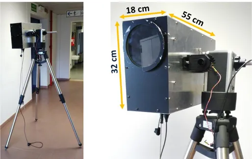
The light generated by optical devices inside the Control Box is delivered by means of an optical fiber to a projection system installed inside a lightweight aluminum case, the Projection Box (Fig.3.3), that can be fixed on any manual or motorized mount for ease of pointing toward the telescope to be calibrated. Inside the Projection Box, the light from the fiber optic is converted, by reflection on a parabolic mirror, to a slightly divergent beam (aperture of the cone ≈ 1.4°) so that, at the distance where the telescope is located, the light beam will illuminate an area much larger than the telescope aperture.
The intensity of the output light beam is monitored by means of a NIST-calibrated photodiode whose signal is delivered to the control PC that will use this information to adjust the light source intensity so to keep the output flux at the desired level for as long time is required by the measurements.
Temperature and humidity sensors are used to monitor the environment inside the Projection box and, when necessary, a heating system will be activated to avoid humidity condensation on the output quartz window (transparent in the UV region), and to keep the internal monitoring photodiode at a stable temperature.
The far-field illumination pattern of the projected beam is expected to be uniform to better than 1 % level in the central region but, to correct for any eventual vignetting, the beam characteristics will be accurately measured with a dedicated calibration campaign; while the internal monitoring photodiode provides a signal proportional the overall intensity of the output light beam, to asses the far–field illumination uniformity it is necessary to use an external, absolute calibrated, photon detector placed far enough (? 100 m) from the Illuminator so to avoid the near-field proximity effects; this reference detector will be illuminated through a calibrated diameter pin hole so the absolute photon density at the selected distance is obtained by the ratio between the detector signal of and the pin-hole area.
By performing then, with a motorized mount, horizontal and vertical scans of the Projection Box pointing direction, the spatial uniformity of the projected beam with a fine angular resolution will be obtained. Once calibrated, the flux at any distance from the Illuminator is then simply obtained by proper geometrical scaling of the measured illumination pattern, corrected for the atmospheric attenuation.
3.4 OPERATION
The distance from the telescope at which the Illuminator can be placed may vary according to the telescope size and the specific aspect of the telescope response to be tested; in general, it should be placed far enough from the telescope so that its light is focused onto a few camera pixels, but it must also be taken into account the increase with distance of systematic uncertainty associated to the atmospheric attenuation; in fact, while the
Figure 3. The Illuminator Projection Box fixed on a tripod with a motorized alt-azimuth mount.
beam attenuation (≈ 4 % per km at 400 nm) due to Rayleigh scattering from air molecules can be rather well computed from the knowledge of the local barometric pressure, the attenuation due to presence of aerosols is highly variable from night to night, from nearly zero up to a few % per km, and therefore requires additional dedicated measurements. To completely eliminate the uncertainty due to the atmospheric transmission and propagation, two NIST-calibrated telescopes, UVscope and/or UVSiPM, working in single photon counting, placed on the ASTRI SST-2M supporting structure, will be used to monitor the light flux reaching the telescope aperture.
The minimal distance at which the incident light is focused onto a few pixels depends essentially on the radius of telescope primary mirror; in the case of ASTRI SST-2M (4.3 m diameter primary mirror) we obtain from ray-tracing simulations that a point-like source would rather well focused when it is placed at ≈ 1 km distance from the telescope; if placed at this distance, an 1 mW output beam from the Illuminator would produce at telescope aperture a photon flux density of a few thousand photons m−2ns−1, more than enough to saturate the dynamical range of the camera electronics.
Beside the measurement of the overall end-to-end telescope response, the Illuminator system allows for a wide variety of calibration procedures that require the use of a reference light source from a fixed position for extended period of time; as example, the high resolution telescope vignetting map can be obtained by steering the telescope axis so that the light from the Illuminator is focused, one after the other, at the center of each camera pixel. Relative reflectivity of the individual hexagonal segments forming the primary mirror can also be obtained by tilting the mirror segments, one after the other, from the nominal orientation.
Another important aspect of the telescope response that can be accurately measured by using the Illuminator system is the point spread function of the telescope; the actual size of the optical spot can be in fact larger than expected from a Montecarlo simulation because of the contribution of small deformations and scatterings in the optical system. In this measurement the accurate knowledge of the absolute illumnation level is not relevant so the Illumnator will be placed as far as possible from the telescope. In any case, the actual measurements obtained by using the Illuminator will be compared to the ones obtained by a computer ray tracing simulation where the telescope model is illuminated by a point–like source placed at the same distance as the Illuminator from the telescope. This allows either to validate the telescope model or to indicate where it should be modified.
Proc. of SPIE Vol. 9906 99063S-5
4. CONCLUSION
We have illustrated the innovative calibration strategy developed for the ASTRI SST-2M telescope and, in particular, one of the auxiliary devices, the Illuminator, which will be used to verify the end-to-end optical throughput of telescope at several different wavelengths and off-axis angles.
The first prototype of the Illuminator is currently under construction and a complete test will be performed night-time on field, at Serra La Nave. The light emitted by the Illuminator, under different setup condition of wavelength, intensity and pulse length will be received by a NIST-calibrated photon detector to evaluate the far–field illumination uniformity, the remote control system and the full capabilities of the system.
The Illuminator, currently under development for the absolute end-to-end calibration of the ASTRI SST-2M prototype, thanks to a flexible design can be easily adapted for use on any other CTA telescope; in this way, one after the other, the whole array will be calibrated against the same reference light source.
A part that during the initial telescope commissioning, the Illumnator is not expected to be used frequently, so a reduced number of devices will be assembled for each of the two (north ant south) CTA sites. Whenever it will be necessary to verify the calibration status of a telescope, the Illumnator will be placed, during the day, in a predefined position, optimized for the selected telescope, and then remotely activated during the night. As the light from the Illuminator is emitted in a narrow cone, almost parallel to ground, its light will be detactable only by the CTA telescope pointing directly toward it, while all the other telescopes, pointing at several degrees above horizon, can perform their scientific observations without any disturbance from the Illuminator activity.
ACKNOWLEDGMENTS
This work is supported by the Italian Ministry of Education, University, and Research (MIUR) with funds specifically assigned to the Italian National Institute of Astrophysics (INAF) for the Cherenkov Telescope Array (CTA), and by the Italian Ministry of Economic Development (MISE) within the “Astronomia Industriale” program. We acknowledge support from the Brazilian Funding Agency FAPESP (Grant 2013/10559-5) and from the South African Department of Science and Technology through Funding Agreement 0227/2014 for the South African Gamma-Ray Astronomy Programme. We gratefully acknowledge support from the agencies and organizations listed under Funding Agencies at this website: http://www.cta-observatory.org/.
This paper has gone through internal review by the CTA Consortium.
REFERENCES
[1] Pareschi, G. e. a., “The ASTRI/CTA mini-array of Small Size Telescopes as a precursor of the Cherenkov Telescope Array,” in [AAS/High Energy Astrophysics Division ], AAS/High Energy Astrophysics Division 14, 116.25 (Aug. 2014). 1
[2] Acharya, B. S., Actis, M., Aghajani, T., Agnetta, G., Aguilar, J., Aharonian, F., Ajello, M., Akhperjanian, A., Alcubierre, M., Aleksi´c, J., and et al., “Introducing the CTA concept,” Astroparticle Physics 43, 3–18 (Mar. 2013). 1
[3] Vercellone, S., for The ASTRI Collaboration, and CTA Consortium, f. T., “The ASTRI mini-array within the future Cherenkov Telescope Array,” ArXiv e-prints (Aug. 2015). 1
[4] Canestrari, R., Giro, E., Antolini, E., Bonnoli, G., Cascone, E., La Palombara, N., Leto, G., Pareschi, G., Scuderi, S., Stringhetti, L., Tanci, C., and Tosti, G., “The ASTRI SST-2M prototype for the Cherenkov Tele-scope Array: opto-mechanical test results,” in [Society of Photo-Optical Instrumentation Engineers (SPIE) Conference Series ], Proc. SPIE 9603, 960303 (Sept. 2015). 1
[5] Catalano, O., Maccarone, M. C., Gargano, C., La Rosa, G., Segreto, A., Sottile, G., De Caprio, V., Russo, F., Capalbi, M., Sangiorgi, P., Bonanno, G., Grillo, A., Garozzo, S., Marano, D., Billotta, S., Romeo, G., Stringhetti, L., Fiorini, M., La Palombara, N., Incorvaia, S., Toso, G., Impiombato, D., and Giarrusso, S., “The camera of the ASTRI SST-2M prototype for the Cherenkov Telescope Array,” in [Ground-based and Airborne Instrumentation for Astronomy V ], Proc. SPIE 9147, 91470D (July 2014). 1
[6] Rodeghiero, G., Catalano, O., Segreto, A., De Caprio, V., Giro, E., Lessio, L., Conconi, P., and Canestrari, R., “Illumination technique for the relative calibration of the ASTRI SST-2M camera,” Nuclear Instruments and Methods in Physics Research A 764, 176–185 (Nov. 2014). 2
[7] Maccarone, M. C., Catalano, O., Giarrusso, S., La Rosa, G., Segreto, A., Agnetta, G., Biondo, B., Mangano, A., Russo, F., and Billotta, S., “Performance and applications of the UVscope instrument,” Nuclear Instru-ments and Methods in Physics Research A 659, 569–578 (Dec. 2011). 2
[8] Sottile, G., Russo, F., Agnetta, G., Belluso, M., Billotta, S., Biondo, B., Bonanno, G., Catalano, O., Giar-russo, S., Grillo, A., Impiombato, D., La Rosa, G., Maccarone, M. C., Mangano, A., Marano, D., Mineo, T., Segreto, A., Strazzeri, E., and Timpanaro, M. C., “UVSiPM: A light detector instrument based on a SiPM sensor working in single photon counting,” Nuclear Physics B Proceedings Supplements 239, 258–261 (June 2013). 2
Proc. of SPIE Vol. 9906 99063S-7