Titolo
Specifica tecnica di fornitura e set-documentale relativo
all'approvvigionamento di una macchina di Detonation Spray per la realizzazione di coating su materiali strutturali.
Descrittori
Tipologia del documento: Collocazione contrattuale:
Specifica Tecnica
Accordo di programma ENEA-MSE: tema di ricerca "Nuovo nucleare da fissione"
Metallurgia
Nuove tecnologie
Argomenti trattati:
Sommario
I processi di deposizione basati sul metodo Detonation Spray sono di grande interesse per la comunità scientifica LFR, in quanto consentono la deposizione di strati sottili, fino a 20J...un su substrati austenici e ferritici.
Il presente documento sintetizza le attività in corso sul DS presso ENEA Brasimone.
Note Copia n. Incarico a: NOME J _ 2 FIRMA NOME
1
FIRMAo
Summary
2. THERMAL SPRAYING ... 3
3. DETONATION GUN SPRAYING ... 4
4. THE ENEA DETONATION SPRAY EQUIPMENT ... 5
1. INTRODUCTION
Thermal spraying is an effective and low cost method to apply thick coatings to change
surface properties of the component. Coatings are used in a wide range of applications
including automotive systems, boiler components, and power generation equipment, chemical
process equipment, aircraft engines, pulp and paper processing equipment, bridges, rollers and
concrete reinforcements, orthopedics and dental, land-based and marine turbines, ships [1].
Among the commercially available thermal spray coating techniques, Detonation Spray (DS)
and High Velocity Oxy Fuel (HVOF) spray are the best choices to get hard, dense and wear
resistant coatings as desired. The objective of the work is to analyze the role of detonation gun
spray coating to enhance the properties of surface of substrate to counter the problems like
erosion, residual stress, fretting fatigue, thermal behavior and corrosion etc.
2. THERMAL SPRAYING
Thermal spraying has emerged as an important tool of increasingly sophisticated surface
engineering technology. The different functions of the coating, such as wear and corrosion
resistance, thermal or electrical insulation can be achieved using different coating techniques
and coating materials . Thermal spraying is the application of a material (the consumable) to a
substrate by melting the material into droplets and impinging the softened or molten droplets
on a substrate to form a continuous coating. There are many thermal spray coating deposition
techniques available, and choosing the best process depends on the functional requirements,
adaptability of the coating material to the technique intended, level of adhesion required,
(size, shape, and metallurgy of the substrate), and availability and cost of the equipment.
Thermal spray processes that have been considered to deposit the coatings are enlisted below:
(1) Flame spraying with a powder or wire
(2) Electric arc wire spraying
(3) Plasma spraying
(4) Spray and fuse
(5) High Velocity Oxy-fuel (HVOF) spraying
(6) Detonation Gun.
3. DETONATION GUN SPRAYING
D-gun spray process is a thermal spray coating process, which gives an extremely good
adhesive strength, low porosity and coating surface with compressive residual stresses .A
precisely measured quantity of the combustion mixture consisting of oxygen and acetylene is
fed through a tubular barrel closed at one end. In order to prevent the possible back firing a
blanket of nitrogen gas is allowed to cover the gas inlets. Simultaneously, a predetermined
quantity of the coating powder is fed into the combustion chamber. The gas mixture inside the
chamber is ignited by a simple spark plug. The combustion of the gas mixture generates high
pressure shock waves (detonation wave), which then propagate through the gas stream.
Depending upon the ratio of the combustion gases, the temperature of the hot gas stream can
go up to 4000 deg C and the velocity of the shock wave can reach 3500m/sec. The hot gases
generated in the detonation chamber travel down the barrel at a high velocity and in the
process heat the particles to a plasticizing stage (only skin melting of particle) and also
accelerate the particles to a velocity of 1200m/sec. These particles then come out of the barrel
and impact the component held by the manipulator to form a coating. The high kinetic energy
of the hot powder particles on impact with the substrate result in a build up of a very dense
and strong coating. The coating thickness developed on the work piece per shot depends on
the ratio of combustion gases, powder particle size, carrier gas flow rate, frequency and
distance between the barrel end and the substrate. Depending on the required coating
thickness and the type of coating material the detonation spraying cycle can be repeated at the
rate of 1-10 shots per second. The chamber is finally flushed with nitrogen again to remove all
the remaining “hot” powder particles from the chamber as these can otherwise detonate the
explosive mixture in an irregular fashion and render the whole process uncontrollable. With
this, one detonation cycle is completed above procedure is repeated at a particular frequency
until the required thickness of coating is deposited. The chamber is finally flushed with
nitrogen again to remove all the remaining “hot” powder particles from the chamber as these
can otherwise detonate the explosive mixture in an irregular fashion and render the whole
process uncontrollable. With this, one detonation cycle is completed above procedure is
repeated at a particular frequency until the required thickness of coating is deposited.
Fig.1. Detonation Gun process
4. THE ENEA DETONATION SPRAY EQUIPMENT
As a first step at ENEA Brasimone for coating manufacturing, CCDS200 DS coating machine
from STPC company, Novosibirsk, Russia, has been purchased and installed. It has to be
underlined that STPC is the only vendor worldwide of this machine, originally trademark of
Praxair ® USA. Together with an installation at Grenoble University, it will be the only
european facility DS based.
5. ANNEX
1. Detonation spraying technology Description
2. Thermal Spray Booth Design Guidelines
Detonation spraying technology Description
The detonation spraying complex «CCDS-2000» is designed to produce powder coating
by spraying various powder materials on the surface of objects accessible for the direct
high-speed spray flow. The complex consists of the detonation gun (gun with
manipulation system), the control unit and the chiller.
The working principle of the CCDS2000 gun is based on the following basic
procedures:
• the barrel, open at one end, is filled with an explosive gas mixture;
• the portion powder is injected in the barrel;
• detonation is initiated at the closed end of the barrel; burning explosion products
accelerate the powder, heating it up to the melting temperature and deposit it onto the
object’s surface;
• after each shot the barrel is purged by nitrogen;
• once the heated powder particles hit the working surface of the object they firmly
attach to the surface forming a coating up to 10 microns thick;
• the desired thickness of coating is achieved by a sequence of shots, during which the
object can be moved using the manipulator.
CCDS2000 D.Gun is controlled by the industrial computer unit, which is used to
program the spraying procedure and to coordinate the movement of work piece; during
the spraying process the computer unit controls the program’s progress. The technology
of spraying can be easily modified, and the programs can be stored on external media
carriers (flash disks).
1.
Facility Requirements
1.1
Ventilation and spray booth
The CCDS2000 systems require a thermal spray booth with sufficient room (W/L
3.5m/3.5m or more), air ventilation and sound insulation. The spray booth should have
forced ventilation that replaces the whole (95%) air volume every 1-2 minutes. The
exhaust ventilation should have a dust collector. Noise mufflers should be installed in
the inlet and outlet ventilation.
The lighting in the spray booth should be explosion-proof. The spray booth should have
an easily breakable window at least 1 m
2in area. In a wall of the spray booth should be
a hermetic observation window of ~ 0.4 m
2in area, made of double glass panes 20 mm
thick, and a soundproof channel for cabling (~ 100 ×100 mm).
The compressed air source (8bar) should be in the spray booth (for target part cooling).
Door of spray booth should be equipped with switch, to be connected to computer
controller, to control it.
1.2 Sound Attenuation
Reduce the noise level from 140 dBA to the required safe 8-hour exposure limit. (In
Russia, this is 85 dBA.) This can be done by enclosing the spray system in a properly
designed booth that will absorb the sound. Due to specific nature of the detonation
spraying process, spray booth should be able to absorb low frequency impulse noise.
We recommend double wall design. Standard thermal spray booth (which is used for
other thermal spray equipment) can’t provide necessary sound isolation. Call
your
spray booth supplier for more information.
1.3
Safety Equipment
Your safety equipment should include appropriate ear protection for 135 dBA, safety
goggles for eye protection, and clothing protection such as flame resistant laboratory
coats. Respirators for breathing protection should also be part of safe thermal spraying.
1.4
Water
20 liters of filtered and clean water required for the CCDS2000 chiller.
Gas Supply System.
Gas supply system should be designed and produced by customer side according listed
parameters.
Gas and Fuel Purity Recommendations
Gas purity levels are important to optimum Detonation Gun life and proper
system operation. Gases of at least 99.995 percent purity are preferred for
prolonging the life of Detonation Gun equipment.
Acetylene gas parameters
Volume fraction of acetylene, %, not less---99.5
Volume fraction of air and other badly soluble in water gases,
%,no more ---0.5
Volume fraction of Phosphine PH
3, % no more---0.005
Volume fraction of hydrogen sulphide H
2S, % no more---0.002
Mass concentration of water steams at temperature
200 С and pressure 101.3 kPa , g/m
3not above---0.4
1.5 Oxygen
A maximum oxygen flow of 10 m
3/h at 1.5-1.6 bar is needed for CCDS2000 gun. Use
only stainless steel supply piping. Usually, a minimum 1/2 inch (12.7 mm) ID
stainless steel line (cleaned for oxygen service) is required, depending on the number of
elbows in the line. A bulk liquid oxygen system may require a low pressure, high flow
regulator, depending on the length of piping from the supply to the Gun. When using
low pressure liquid oxygen cylinders, consult your factory representative for more
information. When using high pressure cylinders, you must use two stage pressure
regulation system, first special oxygen regulator to reduce pressure to 10 bar, and
second HIGH FLOW oxygen regulator to reduce pressure to 1.5 bar .
The oxygen lines must be specially cleaned for oxygen service. Oils or
contaminants in the lines can cause fire or explosion or equipment damage.
1.6
Acetylene Fuel
A maximum acetylene flow of 5 m
3/h at 1.35-1.45 bar is needed for CCDS2000 gun.
Use only stainless steel supply piping. Usually, a minimum 1/2 inch (12.7 mm) ID
stainless steel line (cleaned for oxygen service) is required, depending on the number of
elbows in the line. When using low pressure acetylene cylinders, use only HIGH FLOW
acetylene regulator to reduce pressure to 1.5 bar.
1.7 Propylene/Propane Fuel
A maximum propylene/propane flow of 5 m
3/h at 1.8 bar is needed for CCDS2000 gun.
Use only stainless steel supply piping. Usually, a minimum 1/2 inch (12.7 mm) ID
stainless steel line (cleaned for oxygen service) is required, depending on the number of
elbows in the line. When using low pressure cylinders, use only HIGH FLOW
propylene regulator to reduce pressure to 1.8 bar.
2.3.8 Inert Gas (Nitrogen)
A maximum nitrogen flow of 20 m
3/h at 1.8-2.0 bar is needed for CCDS2000 gun. Use
only stainless steel supply piping. Usually, a minimum 1/2 inch (12.7 mm) ID
stainless steel line (cleaned for oxygen service) is required, depending on the number of
elbows in the line. When using high pressure cylinders, you must use two stage pressure
regulation system, first special nitrogen regulator to reduce pressure to 10 bar, and
second HIGH FLOW nitrogen regulator to reduce pressure to 2 bar .
For any questions, contact STPC Ltd.
[email protected]
Thermal Spray Booth Design Guidelines
Prepared by the ASM-TSS Safety Committee Key Document Authors:
Douglas J. Gifford, Praxair Surface Technologies, Inc. Larry Pollard, Progressive Technologies, Inc.
Gregory Wuest, Sulzer Metco (US), Inc.
Randy C. Fletcher, Praxair Surface Technologies, Inc.
TSS Safety Committee Members:
Gregory Wuest Chairman
Sulzer Metco (US), Inc.
Richard Neiser
Sandia National Laboratories
Lysa Russo
SUNY at Stony Brook
Daryl Crawmer
Thermal Spray Technologies, Inc.
Klaus Dobler
St. Louis Metallizing Company
Douglas J. Gifford
Praxair Surface Technologies, Inc.
Donna Guillen
Idaho National Engineering and
Environmental Laboratories
Thermal Spray Booth Design Guidelines
DISCLAIMER:
This document represents a collective effort involving a substantial number of volunteer specialists. Great care has been taken in the compilation and production of this document, but it should be made clear that NO WARRANTIES, EXPRESS OR IMPLIED, INCLUDING, WITHOUT LIMITATION, WARRANTIES OF MERCHANTABILITY OR FITNESS FOR A PARTICULAR PURPOSE, ARE GIVEN IN CONNECTION WITH THIS DOCUMENT. Although this information is believed to be accurate by ASM International®, ASM cannot guarantee that favorable results will be obtained from the use of this document alone. This document is intended for use by persons having technical skill, at their sole discretion and risk. It is suggested that you consult your own network of professionals. Since the conditions of product or material use are outside of ASM’s control, ASM assumes no liability or obligation in connection with any use of this information. No claim of any kind, whether as to products or information in this document, and whether or not based on negligence, should be greater in amount than the purchase price of this product or publication in respect of which damages are claimed. THE REMEDY HEREBY PROVIDED SHOULD BE THE EXCLUSIVE AND SOLE REMEDY OF BUYER, AND IN NO EVENT SHOULD EITHER PARTY BE LIABLE FOR SPECIAL, INDIRECT OR CONSEQUENTIAL DAMAGES WHETHER OR NOT CAUSED BY OR RESULTING FROM THE NEGLIGENCE OF SUCH PARTY. As with any material, evaluation of the material under end use conditions prior to specification is essential. Therefore, specific testing under actual conditions is recommended.
Nothing contained in this document should be construed as a grant of any right of manufacture, sale, use, or reproduction, in connection with any method, process, apparatus, product, composition, or system, whether or not covered by letters patent, copyright, or trademark, and nothing contained in this document should be construed as a defense against any alleged infringement of letters patent, copyright, or trademark, or as a defense against liability for such infringement.
Comments, criticisms, and suggestions are invited, and should be forwarded to the Thermal Spray Society of ASM International®.
CONTENTS
1. SCOPE... 5
2. OVERVIEW... 5
3. SPECIAL TERMINOLOGY USED WITHIN THIS GUIDELINE... 6
4. RELATED STANDARDS AND DOCUMENTS ... 7
5. TERMINOLOGY/DEFINITIONS... 10
6. BOOTH STRUCTURE AND SOUND SUPPRESSION ... 14
6.1. Scope... 14
6.2. Configuration ... 15
6.3. General Construction... 15
6.4. Sound Hazards and Control ...17
6.5. Powder and Dust Control... 20
6.6. Radiation Control ... 21
6.7. Safety Interlocks ... 22
6.8. Warning / labeling ... 23
6.9. Maintenance Issues (Safety Related)... 23
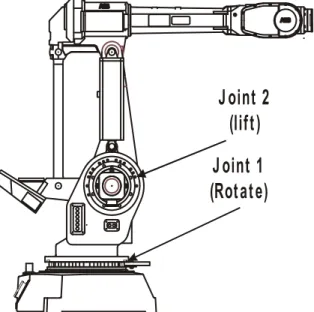
7. ROBOTICS AND TORCH/PART MANIPULATION ... 24
7.1. Scope... 24
7.2. Robotic Arms and Robot Systems... 24
7.3. Installation Configuration and Restricted Space... 25
7.4. Teach Mode... 26
7.5. Other (Non-Robotic) Torch/Part Manipulation Systems ... 27
7.6. ANSI Risk Assessment... 27
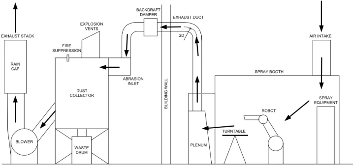
8. VENTILATION AND FILTRATION... 28
8.1. Scope... 28
8.2. Reasons for Ventilation and Filtration... 28
8.3. Types of Dust Collection Equipment ... 29
8.4. Design Considerations... 29 8.5. Operation/Maintenance Considerations ... 34 8.6. Example Case ... 36 9. PIPING GUIDELINES ... 37 9.1. Scope... 37 9.2. Typical Gases/Fluids ... 37 9.3. Supply Planning... 37 9.4. Piping Materials ... 38 9.5. Piping Design... 40 9.6. Piping Components ... 40
9.8. Area Classification ... 41
9.9. Piping Fabrication ... 41
9.10. Piping System Integrity Monitoring ... 42
10. ELECTRICAL GUIDELINES ...43
10.1. Scope... 43
10.2. General Topics ... 43
10.3. Gas and Electrical Interlocking ... 44
10.4. Area Classification ... 45
11. ERGONOMICS ... 46
11.1 Scope... 46
11.2 Design Considerations... 46
11.3 Repetitive and Force of Operations... 47
1. SCOPE
The scope of this document discusses the safety issues associated with the design and operation of thermal spray booths and boxes. The document’s scope is limited to thermal spray booth or spray box structures and the equipment, or systems – internal and external – required to operate the thermal spray processes within these enclosures. This includes the mitigation of sound, dust and fume, ultraviolet light, and mechanical (robotics) hazards that must be contained or controlled by a properly designed and properly used enclosure. This document does not cover the Personal Protective Equipment (PPE) needs of any operator that may enter the booth before or after the process is active. It addresses only the design of spray booths that allow normal operation of the process from outside the booth itself (sometimes referred to as a “closed system”). This document does not address manual operation of the process with the operator inside the booth itself. The document does not cover vacuum plasma spray (VPS) chambers because they are substantially different from atmospheric enclosures in their design, operation and safety considerations.
These guidelines are written within the context of the prevailing internationally accepted practices and
standards, as well as United States laws and regulations. They are intended to have worldwide application. It is incumbent upon each individual, company, or institution referencing these guidelines, to ensure compliance with all relevant local country/community laws, rules and regulations, and to apply generally accepted, good
engineering practice to the design, fabrication, and installation of thermal spray systems that are safe, reliable, and legal.
Thermal Spray booth design is complex and involves many different engineering disciplines. Because of the diverse nature of thermal spray process requirements, this document alone cannot provide all the information needed for booth design. Suppliers/professionals with expertise in specific aspects of booth design (ventilation, sound suppression, piping, etc.) should be consulted to ensure design safety and integrity.
This guideline is intended for use in conjunction with the other reference publications, local publications, and applicable standards. An extensive, but not comprehensive, list of these is included in Section 4, RELATED
STANDARDS AND DOCUMENTS
2. OVERVIEW
The primary role of a thermal spray enclosure is to contain and/or control various hazards associated with thermal spray processing of materials. Historically, thermal spray booths were used to shield the shop floor from the intense sound pressures, dust and fumes, and ultraviolet light generated during spray operations. In the past decade, the introduction of robotics has led to an expanded role for booths as barriers to protect humans from being struck by fast-moving robotic arms. The most modern spray enclosures are now designed to minimize operator exposure to a variety of thermal spray hazards. Spray boxes and fully automated spray booths that do not require an operator to be present in the spray environment are becoming more common, and in many situations have become an accepted requirement.
The use of an enclosed space to reduce hazards has considerably increased the safety of thermal spray operators and shop personnel that work in the vicinity of thermal spray devices. However, an enclosure
introduces new hazards that must be dealt with. A wide variety of gases are used in thermal spray processing. Unless proper care is taken, it is possible to create dangerous situations within an enclosure. An inert gas leak can displace the air, leading to an asphyxiation hazard. A fuel leak or build-up of an explosive metal powder can set up the possibility of a violent explosion. Thermal spray enclosures must be designed to provide simple egress of operators during an emergency situation. Operators inside a spray booth may be unaware of emergency situations on the shop floor, such as fire alarms, unless special provisions are made.
The thermal spray enclosure is the most important safety device used in thermal spray processing. Because the spray operations are conducted within its confines, all of the energy sources (gas, electricity, and water), the feedstock materials, and all of the process effluents (heat, dust, fumes, sound and ultraviolet light) are present. Proper mitigation of all of these hazards requires careful thought in the design and operation of a spray booth.
3. SPECIAL TERMINOLOGY USED WITHIN THIS GUIDELINE
Within this document, distinct terminology is employed to differentiate between Requirements,
Recommendations, and Considerations. The meanings of these terms in any word form are defined below
and wherever these terms are used in these guidelines in the context of a safety practice, they are presented in
bold italic typeface.
A Requirement is a safety practice that must be conformed to at any thermal spray facility. Typically a requirement is already an industry-accepted or government-regulated practice about which there is little or no debate regarding the importance of its safety-related issues, and the methods by which identified hazards are mitigated. An example of a Requirement would be that the piping used to carry acetylene may not be fabricated from alloys that contain more than 65% by weight of copper or other identified reactive constituents. It is well known that that the use of copper tubing for carrying acetylene is very dangerous, due to the formation of unstable compounds, and it is difficult to imagine any thermal spray installation in which copper tubing is acceptable for carrying acetylene.
A Recommendation is applied to a safety practice that should be carefully considered before a reader chooses to ignore it. Recommendations should not be dismissed lightly. There may be certain situations in which a recommendation can be ignored, but in general, most thermal spray facilities should implement all
recommendations. An example of a Recommendation would be the installation of a manual shutoff valve (Station Outlet valve) for each gas at each spray booth in a facility. There may be situations in which installing this valve is not appropriate; however, before deciding to ignore this recommendation, the thermal spray facility designer should carefully think through how isolating the gases from an individual booth would be accomplished, if necessary.
A Consideration is a safety practice that may be contemplated for implementation at a thermal spray facility. Considerations are safety enhancements that may not be essential or applicable to all situations. An example of a Consideration would be the installation of an oxygen or combustible gas monitor in a spray booth, the purpose of which is to detect the formation of a dangerous atmosphere. The ability to detect an asphyxiating or combustible atmosphere is a measure that improves safety. However, these sensors are prone to failure, and can be expensive to install and maintain. By properly designing a booth with various interlocked solenoid valves and natural ventilation, the possibility of forming a dangerous atmosphere can be reduced to the point that monitors do not provide a substantial increase in safety.
4. RELATED STANDARDS AND DOCUMENTS
Where standards and other documents are referenced in this publication, they refer to the latest edition.
U.S. Standards
Publication Title
Available
from:
ASTM Publications: A53
Specification for Pipe, Steel Black and Hot-Dipped, Zinc-Coated Welded and Seamless
A105 Specification for Forgings, Carbon
Steel, and Piping Components
A106 Specification for Seamless Carbon
Steel Pipe for High-Temperature Service
A182 Specification for Forged or Rolled
Alloy Steel Pipe Flanges, Forged Fittings and Valves and Parts for High Temperatures
A312 Specifications for Seamless and
Welded Austenitic Stainless Steel Pipes
E-84 Surface Burning Characteristics of
Building Materials
E-447 Compressive Strength of Laboratory
Constructed Masonry Prisms
American Society for Testing and Materials
100 Bar Harbor Drive
West Conshohocken, PA 19428-2959 www.astm.org CGA Publications: G-1 Acetylene
G-1.3 Acetylene Transmission for Chemical
Synthesis
G-4 Oxygen
G-4.1 Cleaning Equipment for Oxygen
Service
G-4.4 Industrial Practices for Gaseous
Oxygen Transmission and Distribution Piping Systems
The Compressed Gas Association 1235 Jefferson Davis Highway Arlington, VA 22202
www.cganet.com
ANSI Publications:
ANSI/ASME B31.3 Chemical Plant and Petroleum Refinery Piping
A 13.1 Scheme for Identification of Piping
R15.06 Safety Procedures for Industrial
Robots and Robot Systems
American National Standards Institute
1430 Broadway New York, NY 10018 www.ansi.org
Publication
Title
Available from:
EPA Publications Industrial Ventilation, 23rd edition,
1998
U.S. Environmental Protection Agency
Ariel Rose Bldg.
1200 Pennsylvania Ave., N.W. Mail Code 3213A
Washington D.C. 20460 www.epa.gov
NFPA Publications:
13 Sprinkler Systems
51 Design and Installation of
Oxygen-Fuel Gas Systems for Welding, Cutting and Allied Processes
68 Explosion Deflagrations (Venting)
69 Explosion Prevention Systems
70 National Electric Code, Article 500,
Hazardous Locations
255 Std. Method of Test of Surface
Burning Characterizations of Building Materials
484 Combustible Metals, Metal Powders,
and Metal Dusts.
496 Purged and Pressurized Enclosures
for Electrical Equipment
497M Classification of Gases, Vapors,
Dusts for Electrical Equipment in Hazardous Locations
National Fire Protection Assoc. Battery March Park
Quincy, MA 02269 www.nfpa.org
TSS Publications: SG001-02
Safety Guidelines for the Handling and Use of Gases in Thermal Spraying
SG002-02 Safety Guidelines for Performing Risk
Assessments
ASM International® 9639 Kinsman Road
Materials Park, OH 44073-0002 www.asminternational.org
OSHA Publications Occupational Safety and Health
Administration
1-800-321-OSHA for nearest location
www.osha.gov
SMACNA SMACNA HVAC Duct Construction
Standards – Metal and Flexible SMACNA, Inc. 4201 Lafayette Center Dr.
Chantilly, VA 22021
Ph. 2980; Fax: 703-803-3732
INTERNATIONAL STANDARDS
Publication
Title
Available from:EN ISO 2063 Thermal spraying -- Metallic and other inorganic
coatings -- Zinc, aluminium and their alloys
EN ISO 14231 Acceptance inspection of thermal spraying
equipment
EN ISO 14232 Powders -- Composition and technical supply
conditions
EN ISO 14917 Thermal spraying – Terminology, classification
International Organization For Standardization 1, rue de Varembé, CH-1211 Geneva 20, Switzerland Phone +41 22 749 01 11 Fax +41 22 749 09 47 E-mail [email protected]
5. TERMINOLOGY/DEFINITIONS
ACGIH – American Council of Industrial Hygienists.
Administrative Controls – Reducing the risk of injury through management of the processes and workforce. ANSI – An abbreviation for American National Standards Institute.
ASTM – An abbreviation for American Society for Testing and Materials. AWS – An abbreviation for the American Welding Society.
Approved – Acceptable to the authority having jurisdiction.
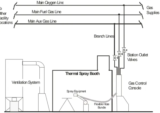
Branch Lines – The piping that leads from the Main pipeline to Station Outlet Valves supplying the Process
equipment.
CGA – An abbreviation for the Compressed Gas Association.
Detonation Gun – A thermal spray device that employs rapid detonation of an oxygen-fuel mixture to heat and
carry coating powders to the surface of a part in order to apply a coating that enhances the part’s surface performance properties.
Dead Air – Areas where there is little or no air motion such that dust or particulates in the air will fall and
accumulate on the booth interior surfaces.
Decibel (dB) – A numerical expression of the relative loudness, or intensity, of a sound. The difference in
decibels between two sounds is ten times the logarithm of the ratio of their power levels. The “A” suffix when
used with dB(dBA) signifies a non-linear averaging of noise levels across ten octave bands to compensate for
human ear sensitivity to sound at various frequencies.
De-ionized Water – Water from which nearly all ions (electrically charged particles) have been removed
returning it to its purest state to minimize corrosion, or other chemical reactions. Often required or recommended by manufacturers for cooling water.
Design Pressure – The same as Maximum Allowable Working Pressure referenced in many codes. This
pressure is typically at least 15% higher than system Operating Pressure,
Dry Ice (CO2 Snow) – the solid state of carbon dioxide. Usually forms when a sudden pressure release of CO2
occurs such as spraying.
Effluent – A term used to encompass all the gases, coating, fumes, etc. emitted from a thermal spray gun or
torch.
Enclosure – The cabinet or housing of apparatus or the fence or wall surrounding an installation to prevent
personnel from personal injury hazards or to protect the equipment from physical damage.
Engineering Controls – Reducing the risk or potential for injury by incorporating safety systems, features,
interlocks, etc. into the design of machines, tools, layouts and processes.
used as a part of, or in connection with, a thermal spray installation.
Ergonomics – The process or science of adapting workstations, tools, equipment and work techniques to be
compatible with human anatomy and physiology so as to reduce the risk of injury due to occupational activity or stresses.
Fuel Gas – Any combustible gas, including hydrogen, propane, propylene, acetylene, MAPP, etc. used in a
thermal spray process.
Fuse – An over-current protective device incorporating a fusible component or link that is heated by excessive
current flow and subsequently separates, or opens, halting the flow of current. A fuse is typically not reusable.
Fumes – Particulate matter consisting of particles generated by the condensation of gases created by
evaporation of melted substances.
Frequency – The number of cycles-per-second of a device, signal, or parameter. Generally expressed in
Hertz (Hz).
Ground Fault (Circuit) Interrupter (GFI or GFCI) – A protection device designed to remove the electrical
power from a circuit when an imbalance of current exists between the supply conductor and the return
conductor indicating the presence of a leakage fault path, usually to ground or earth. Such a fault path could be a result of malfunctioning or damaged equipment. For example: water leaks and subsequent corrosion, or contact with tools or personnel. Early detection of faults and disconnection of power by a GFI device can often avoid or minimize damage or injury.
HEPA – An abbreviation used for High Efficiency Particulate Air. In reference to air filters, it specifies that
99.97% of particles larger that 0.3 micron will be removed from the air stream.
HVOF – High Velocity Oxygen Fuel. This type of high velocity coating process uses a liquid or gaseous fuel
combusted with oxygen to heat and carry coating material to the surface of a part in order to enhance the part’s surface performance properties.
HVAF – High Velocity Air Fuel. This type of high velocity coating process uses a gaseous fuel with air to heat
and carry coating material to the surface of a part to enhance its surface features.
Interlock – A switch or other device that prevents the activation of a piece of equipment when a protective door
is open or other hazards exist.
LPPS – Low Pressure Plasma Spray. See preferred term Vacuum Plasma Spray Deposition.
Lock-out/Tag-out – The process of locking and tagging any energy source (typically a valve or electrical
shutoff) to isolate sources of energy during maintenance/repair and prevent inadvertent operation – or release of energy or hazardous material.
Main Piping – That portion of a gas piping system that leads from a gas supply source to the branch piping. MSDS – An abbreviation used for Material Safety Data Sheets.
Negative Pressure – An area or volume, such as the interior of a spray booth, which is at a lower pressure than
the surrounding area..
NIOSH – National Institute for Safety and Health
Noise - Unwanted sound which may be hazardous to health, interferes with communications, or is disturbing. Operating Pressure – The pressure at which a system normally operates; not the pressure to which a system
may be subjected to during upset, or unusual circumstances. At the inlet to the piping system, the Operating Pressure equals the Supply Pressure. The Operating Pressure in a portion, or all, of a piping system may be reduced with a pressure regulator (pressure reducing valve).
OSHA – Occupational Safety and Health Administration (USA).
Permissible Exposure Limit (PEL) – is the maximum amount or concentration of a chemical that a worker may
be exposed to under OSHA regulations.
Piping – The parts of a fluid/gas system that consist of conduits in the form of rigid pipes, tubing (flexible),
interconnecting fittings, and in-line accessories.
Process Equipment – The mechanical and/or electrical devices and associated control systems that are used
to produce coatings or produce surface enhancements, and whose operation directly affects the chemistry, or the physical properties, of the final product. Typically, this includes gas consoles, regulator panels, hose bundles, powder feeders, gases and gas supplies, and the thermal spray gun or torch.
Purging – The process of admitting an inert gas into one end of a pipeline or container and venting the other
end for a specific period of time. Used to remove (purge) hazardous or combustible materials from the pipeline or container.
PVC – (Polyvinyl Chloride) – A type of material commonly called plastic pipe. It is used for its corrosion
resistance and ease of fabrication, but usually has lower impact resistance and pressure ratings as compared to metal piping.
RIA – Robotic Industry Association. A co-publisher, with ANSI, of robot safety standards.
REL (Recommended Exposure Limit) – An 8 or 10-hour time-weighted average (TWA) or ceiling (C) exposure
concentration recommended by NIOSH that is based on an evaluation of health effects data.
Safeguarded Space – Shielded, fenced, covered, enclosed or otherwise protected by means of suitable covers,
casings or barriers to remove the likelihood of unsafe approach.
SMACNA – Sheet Metal and Air Conditioning Contractors National Association.
Sound – A vibrational disturbance, exciting hearing mechanisms, transmitted in a predictable manner
determined by the medium through which it propagates.
Sound Pressure – Fluctuations in air pressure caused by the presence of sound waves. Sound Pressure Level - The intensity of a sound, expressed in decibels (dB).
Spray Booth – An enclosure for thermal spray processes that is specifically designed to mitigate process
hazards. A spray booth is NOT designed for human occupancy during routine spray operations; however, it is routinely occupied for maintenance and process setup.
Spray (Coating) Box – A spray (coating) box is an enclosure for thermal spray processes that is specifically
designed to mitigate process hazards. These boxes are NOT designed for human occupancy during routine spray operations, process setup and routine maintenance.
booth or a spray (coating) box.
Station Outlet Valve – The shut-off valve located at the downstream end of the branch piping or the point at
which process equipment is connected to the piping system.
Test Pressure – The pressure to which devices/piping are subjected for design testing purposes. Typically this
pressure is 1.3 to 1.5 times greater than the Operating Pressure for pressure vessels; often many times greater for piping.
Threshold Limit Value (TLV) – are guidelines prepared by the American Conference of Governmental
Industrial Hygienists, Inc (ACGIH) to assist in making decisions regarding safe levels of exposure to various
hazards found in the workplace. A TLV reflects the level of exposure that the typical worker can experience without an unreasonable risk of disease or injury.
Turbulent Flow – Flow of air that is not uniformly distributed over a cross section of a pipe, tube or hose,
resulting in unpredictable eddies, vortices, back-flow, and areas where little movement of air occurs.
Vacuum Plasma Deposition (VPD) – A thermal spraying process variation utilizing a plasma gun confined to a
solid enclosure. The enclosure is evacuated and the spraying performed under low pressure, also known as
Vacuum Plasma Spray (VPS), Low Pressure Plasma Spray (LPPS®).
Ventilation System – A complete air handling and filtration system for a thermal spray booth from the intake of
air into the process to the exhaust of the air back into the atmosphere. In this document, the spray booth is considered as part of the exhaust system in regard to air flow.
6. BOOTH STRUCTURE AND SOUND SUPPRESSION
6.1. Scope
This section on Booth Structure and Sound Suppression provides information intended to promote increased safety awareness in the design and configuration of basic booth enclosures for thermal spray installations. The focus of this section is on the key elements of booth structure and how structure and configuration issues impact the safety of operators and employees. The structure of a typical thermal spray booth has the primary function of controlling exposure to the following major hazards:
Excessive sound levels
Powder / dust from the process Gases / Fumes
Visible light and ultraviolet (U.V.) radiation
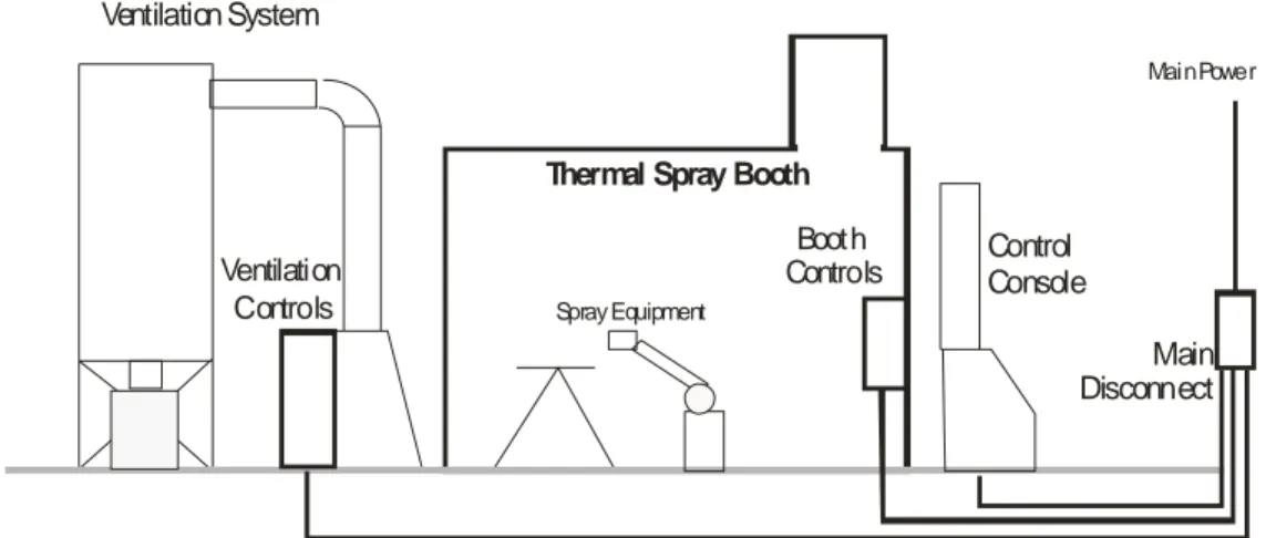
The configuration of a typical thermal spray cell, in most cases, centers on an enclosure structure that works with other sub-systems (interlocks, controls, ventilation/ filtration, etc.) to provide effective control and protection from these major hazards.
Ventilation System
Operator’s
Control
Console
Spray EquipmentBooth
Controls
Ventilation
C ontro ls
Thermal Spray Booth
6.2. Configuration
Typical thermal spray installations include an enclosure that protects the operator and the surrounding areas from the hazards associated with the thermal spray process while it is in operation. There are three main types of enclosures used to contain the process and allow its operator to remain outside its confines:
Walk-in style booth – A Walk-in booth consists of an enclosure that surrounds the process, the part, and the
gun or torch manipulating equipment in such a manner that the operator need not be present in the booth during normal operation. The operator or other personnel are typically in the booth for job setup and routine
maintenance of the equipment, but operation of the process, and the manipulating equipment used to perform the actual thermal spray coating, may be initiated remotely only by the operator with controls located outside of the booth. Interlocks between gases, the process, ventilation, and operator entry are designed accordingly. This style of thermal spray booth is the most common type. This is largely due to its flexibility to accept components, fixtures and equipment with considerable variation in size and configuration with minimal modification and associated costs. Such a configuration, with proper interlocks and safety systems, can satisfactorily limit the exposure of the operator and other personnel to the major hazards associated with thermal spray process and support equipment.
Spray (Coating) box – A Spray box has its enclosure closely fitted to the thermal spray device and part
manipulation equipment. This arrangement allows the operator to load parts for coating through a door while the process is shut off, and never requires entry onto the area where coating takes place. Such an arrangement affords maximum efficiency for dust collection (smallest ventilated volume) and provides the greatest operator safety. Eliminating the need to enter the confines of the spray box provides the maximum level of protection from exposure to particulate matter, fumes, gases, noise, and radiation as well as improved protection from moving mechanical components.
Thru-the-Wall booth – Either of the above types can be configured to allow the passing of parts through a port
or load-lock while the process is in operation, often providing higher productivity than other configurations. Proper design must be followed to limit operator exposure to the major hazards of sound, radiation, or dust. Additionally, care must be taken to properly interlock manipulation equipment operation to protect the operator from potential pinch/crush points associated with the door.
Both the Spray box and Thru-the-Wall booth designs see limited application because of reduced flexibility to changing needs and resultant increased costs of tooling. Both types share many of the same design
requirements of the Walk-in style booth but typically differ considerably in the area of interlocking.
6.3. General Construction
Construction of the basic booth (wall, ceilings, door panels, etc.) must meet the sound attenuation requirements for the specific process in use. Typically, materials that meet sound attenuation requirements easily meet radiation (thermal/visible/UV) and dust control requirements. Thermal spray booth construction is most often of modular acoustical panels or, in some cases, of conventional block and mortar construction.
Modular construction - This construction method typically comprises sheet steel panels filled with a form of
non-flammable insulation such as fiberglass. The panels typically consist of solid steel sheet on one side and perforated metal on the other. The enclosure is normally constructed with the perforated side of the panels toward the sound source.
Block and Mortar – This construction method is rarely used today due to economic constraints and lack of
portability. However, this method of construction can easily meet basic safety requirements for operator protection.
General Requirements
Non-flammable – The nature of the thermal spray process requires that general booth construction materials be
non-flammable.
Sound Suppression – The design and construction of the booth is the single most significant factor determining
the attenuation of sound associated with the thermal spray process. It is required that sound be attenuated to acceptable levels as dictated by local codes and standards to ensure operator protection. Additional information on this topic can be found in Section 7.5.
Access Doors / Windows
Design and construction of booth doors are critical to providing adequate sound suppression and operator protection from powders, dusts, gases, fumes, and UV radiation.
It is required that doors be provided with positive latches, hinges and seals that ensure continued protection of personnel from the above hazards.
The weight of the door, its frequency of access, and difficulty of operation should be considerations in determining whether the door should be mechanized.
It is required that observation windows be constructed of multi-layered transparent plastic material or tempered glass for breakage resistance and safety. Windows employed in spray booths using plasma or wire arc spray processes require the appropriate level of shading for UV protection. This may be a roll-up style shade. A prominently displayed warning sign is required advising of the dangers of UV exposure.
Booth Wall and Ceiling Penetrations
Penetrations, or openings, through sound control walls are a necessary conduit for electrical cables and gas and/or water hoses and pipes. Suitable sound absorbent materials are typically used to control the sound conducted and radiated through such openings. It is required that all openings be sealed to minimize sound leakage and maintain an adequate seal against powder / dust leakage.
Penetrations through typical panels are required to be lined such that hoses and cables are not exposed to sharp edges.
Booth Ceilings / Roofs
Often the ceiling or roof area of a thermal spray booth is utilized as a location for the mounting of equipment such as fans, power sources, and filtration equipment. Additionally, the ceiling inside of a booth is often required to support small hanging hoists and/or other parts handling devices. Sound insulation panels are often of lightweight construction that needs adequate reinforcement to meet equipment support needs. Adherence to all local building codes for such areas is required.
The typical thermal spray cell ceiling, or roof, is primarily designed for sound control, and as such is typically not designed for carrying loads. It is recommended that due consideration be given to the design load capacity of the ceiling/roof of the thermal spray booth if these surfaces and areas are to be used for mounting and storage.
Consideration should be given to:
• Proper reinforcement for the mounting of all hoists and other part-handling devices.
• Appropriate reinforcement of roof areas to properly support mounted equipment.
• Adequate walk areas to facilitate safe servicing of equipment.
• Railings, toe boards, and other appropriate fall-protection devices to ensure that the top of the booth
is a safe workplace. Openings in the railing must be chained or gated.
• Ladders or stairs to provide easy and safe access to the booth roof area.
Consideration should be given to regular cleaning of the interior of a thermal spray booth. The frequency of
cleaning requirements depends on the process type, coating material type, part configuration and vent system design.
Since many thermal spray powders are considered hazardous materials, often the safest cleaning method is a HEPA vacuum cleaner. In some cases, washing of floors and/or walls may be necessary. In many cases, the waste cleaning liquid will be considered hazardous waste and will require handling that complies with local regulations.
Typical perforated sound panels become impregnated with thermal spray particulate over years of booth operation. Although this does not seem to affect sound absorption performance, washing of such used panels with liquid presents unique problems and should be avoided. In addition, used panels, when shipped or disposed of, often must be categorized as hazardous waste.
6.4. Sound Hazards and Control
Noise and Noise Level
Noise is defined as an unneeded and objectionable sound. Excessive noise, common to most all thermal spray devices, can reduce productivity, slow reaction times, and can cause tension, hearing impairment, and
nervousness.
The Occupational Safety and Health Administration (OSHA) and similar organizations worldwide require employers to provide safe working conditions. These organizations typically do not provide guidelines specific to an industry or process but they do establish general rules for the control of unsafe and unhealthy conditions. Noise level is a measurement of sound wave energy (pressure). The standard unit of sound measurement is decibels (dB). The use of the decibel, a unit based on the logarithm of the sound intensity power, provides a scale that better represents how loud the sound or noise is perceived by a typical human.
Typical Sound Power Levels of Various Sources
Source Sound Power,
Watts
Decibel, dBA
Saturn Rocket 100,000,000 200
Afterburner, Jet Engine 100,000 170
75 Piece Orchestra 10 130 Centrifugal Fan at 13,000 cfm 0.1 110 Automobile on Highway 0.01 100 Food Blender 0.001 90 Dishwasher 0.0001 80 Voice, Normal Conversation Level 0.00001 70
Duct Silencer, self noise
at 1,000 fpm 0.00000001 40
Typical Thermal Spray Noise Levels / Noise duration tolerance
Thermal spray processes generate high noise levels. The following table shows typical noise levels of various processes. Parameter settings and coating types have significant impact on overall sound levels.
Thermal Spray Device Decibel, dBA
Detonation gun 145
HVOF liquid fuel 133
HVOF gaseous fuel 125 - 135
HVAF 133
Wire Flame Spray 118-122
Powder Flame Spray 90-125
Rod Flame Spray Gun 125
Electric Arc 105-119
Air Plasma Spray (APS) 110-125
Vacuum Plasma Deposition (VPD)/LPPS® Ambient 1
Cold Spray 110
Water Stabilized Plasma 125
RF Plasma 95
The table below shows typically accepted tolerable noise limits for various exposure times: the louder the noise level present, the shorter the permissible exposure time.
Tolerable Noise Limits of Various Exposure Times (Source NIOSH – ACGIH)
Exposure Duration (Per Day) Sound Level (dBA)
Hours 16 82 8 85* 4 88 2 91 1 94 Minutes 30 97 15 100 7.5 103 2 109
* OSHA Requirements state that any exposure over this level requires hearing protection.
Typical Booth Acoustical Construction
1
Some processes, such as VPS (also known as Low Pressure Plasma Spray, or LPPS®), are carried out within a vacuum chamber that takes the place of a conventional acoustic enclosure. In many instances, noise from the main process is attenuated beyond the point of being any concern. However, in many cases, continuous noise from pumps, fans and other ancillary equipment is at such a level that steps must be taken to protect personnel appropriately.
Modular construction typically will consist of panels approximately 4 inches (102 mm) in thickness with sheet metal inner and outer walls packed with a sound absorbent material such as fiberglass. More often the inner panel is perforated to better allow the acoustic energy to enter and thus dissipate within the absorbent material. It is common for plasma, electric arc, and HVOF devices to utilize single-walled booths while the lower
frequency sound signatures associated with detonation devices typically will require double-walled booths often with heavier mass sound absorbent materials.
Typically, the supplier of the acoustic enclosure can provide access door and window designs to suit the needs of the installation. It is critical that door seals remain tight and receive regular maintenance attention such that the full acoustic effectiveness of the enclosure can be maintained. Particular attention needs to be given to windows, seals around windows and wall penetrations, seals against the floor, sound reflections of building ceilings, etc.
Numerous alternative solutions can provide good performance for thermal spray processes. Consult with the supplier of the thermal spray device or similar devices to obtain the best advice on solutions for specific acoustic spray booth application and configurations.
Exposure Control
In most situations, it is the employer that has the ultimate responsibility for protecting employees from excessive noise. In the case of new equipment construction, be sure that the vendor provides adequate noise control and that the proper tests are conducted during equipment acceptance to ensure compliance with local safety and health regulations.
Used equipment can often present difficult problems if the appropriate noise control qualities are not designed into the equipment. Given a specific equipment design, certain engineering, administrative and personal protective schemes may help. Some examples are:
Work Area Isolation
Increasing the distance between the noise source and the employee lowers the sound pressure level. The following table lists how increasing distance can reduce decibels in a free field.
Using Distance to Reduce Decibels Distance from
Source Theoretical dBA Reduction
3 feet (1 m) 0
10 feet (3 m) 10
30 feet (9 m) 20
90 feet (27 m) 28
Blocking the path of sound transmission by adding sound absorbing materials to the work area will provide significant noise reduction. Consult noise control experts for material recommendations. Noise may also be isolated by moving its source away from affected personnel or placing the equipment in an acoustically insulated enclosure. Often adding insulation to an existing enclosure can provide additional attenuation.
Plan and Schedule to Reduce Exposure Time
Engineering controls focus on eliminating, reducing, or containing the noise hazard. Administrative controls attempt to reduce exposure time.
Planning and scheduling are best used where spraying is intermittent. Usually, spraying time is a small percentage of the total job compared with setup, surface preparation, and finishing.
If spraying time exceeds the permissible levels for noise exposure, schedule jobs over more than one shift or day to keep exposure within maximum limits. More than one operator can spray jobs to keep the exposure of any one person within limits. Spraying outside of regular plant hours can control exposure of persons near the operation. Also, rotate personnel assignments in the vicinity of the thermal spraying operation to control exposure.
Use of Personal Protective Equipment (PPE)
If generally accepted or local regulatory requirements cannot be met regarding sound exposure, it is required that employers supply and mandate the use of appropriate personal protective equipment.
6.5. Powder and Dust Control
Powder and dust control are mainly provided by the ventilation/filtration system discussed in Section 8; however, some issues are more specifically related to booth structure and controls and as such are deserving of coverage here:
Integrated Design
The booth design needs to be linked with good ventilation flow and control. Often, the early design selections regarding booth or coating box layout can have a major impact on the ability to establish good ventilation flow and the ability to carry waste powder to the filtration system. Specific ventilation areas impacted by booth layout are:
Total air flow and local velocities – Booth layout will affect total air flow capability and will determine local
velocities. Local air velocities will have a significant impact on the ability of the system to capture dust particles and carry them into the ductwork leading to the filters rather then having them settle and accumulate on the booth floor, walls and tooling.
Laminar flow – The smoothest possible flow of air is very beneficial to the effective removal of dust from the
process area carrying it into the ducts leading to the filters. Turbulent flow often will create eddies and low pressure areas that cause dust to be trapped or dropped from the air stream. Necessary and sometimes unnecessary booth obstacles such as tooling, parts to be sprayed, robots, and fixtures in practice detract from smooth air flow however steps can still be taken to maximize performance for any given installation.
Negative Pressure – Exhaust fans, inlet fans (if so equipped) and dampers should be adjusted such that a slight
negative pressure is maintained within the thermal spray booth when closed and operating. Typical booths are not completely airtight. The effect of a slight negative pressure is that small leaks are in an inward direction carrying dust to the interior and the filters rather than leaks in an outward direction that carry dust and fumes into the shop areas.
Entry Timer – A timer should be considered to prevent entry into the booth until a preset time has elapsed after
the shutdown of the process. This allows the ventilation system to clear the air of hazardous dust.
Important: A spray booth with poor ventilation or one that allows entry before the ventilation flow can
adequately remove airborne dust particles may result in unacceptable exposure of entering personnel to dust inhalation hazards. If entry is required, appropriate PPE must be worn.
Typical thermal spray processes radiate energy in both electromagnetic and acoustic forms. Emission of sound (acoustic) energy and its control are adequately covered elsewhere in this document. Electromagnetic radiation associated with thermal spray processes is typically divided into two classes. Such radiation can occur in the visible (or near visible) range and also as un-wanted electromagnetic radiation in the power and radio frequency portions of the electromagnetic spectrum.
Ultraviolet, Bright Visible, and Infrared Radiation are common when using thermal spray devices and certain
precautions are required in order to adequately protect employees from their effects. Typically direct effects will include temporary and/or permanent damage to the eyes as well as burns to the skin.
Electromagnetic Radiation can take the form of unwanted radio-frequency (RF) waves capable of transmission
through the air or along wiring, piping and metal based construction materials. At levels commonly associated with thermal spray devices, it is not likely that RF radiation can approach the levels necessary to cause injury (such as might be experienced in a microwave oven). However, radiated RF energy from machinery (especially thermal spray equipment using electric arcs and arc starters) can cause malfunctions of other equipment which, in turn, could have serious affects on the health and well-being of personnel in the area. Steps are often
required to minimize such radiation and ensure the posting of warnings announcing its presence.
Protection - Ultraviolet, bright visible and infrared radiation
Increasing distance from a radiation source has a considerable effect on the energy level and thus the resultant hazard to personnel. A typical properly interlocked thermal spray booth affords some protection for the operator in that it prevents close observation such as might be an issue with a process such as manual welding.
Arc burns and permanent eye damage can still occur from exposure to the radiation from plasma, electric arc, and some flame processes through windows in the spray booth wall. Proper use of tinted glass and/or pull-down shades can prevent such injuries. A protection scheme suited to the specific process and booth configuration is
required. Consult with the manufacturer of the thermal spray process equipment to determine what steps are appropriate and in keeping with locally established regulations.
Protection – Electromagnetic radiation
Electromagnetic radiation from thermal spray process, also known as EMI/RFI, is most often the result of electric-arc-based processes (electric arc spray, DC and RF plasma). Substantial electric currents in gun cables and ground paths as well as in high-frequency arc starting circuitry are often the cause. Shielding of high-current cables, although effective, is often not possible due to performance degradation.
The problem is often best controlled by arranging equipment such that gun-to-power source electrical cables are the shortest length possible. Also high frequency arc starter assemblies should be located as close to the process gun as possible. Cables such as these can behave as radio frequency transmitting antennae and need to be kept as short as possible. Also, if such process power cables are run parallel and close to metal
conductors such as pipes, structural supports, other cables, etc. transmission and re-radiation can occur. These
recommendations will minimize radiation and control potentially hazardous effects.
Equipment marketed in Europe is now required to meet the EMC (Electromagnetic Compatibility) Directive. This unified European directive requires that machinery pass tests regarding emission of electromagnetic radiation as well as tests verifying the equipment’s resistance to radiation from other equipment.
The equipment supplier is the best source of information regarding radiation and adequate protection from it as well as the appropriate posted warnings that may be required by local codes.
6.7. Safety Interlocks
Safety Interlocks should be incorporated into any good thermal spray booth layout. Such interlocks provide protection from hazards by techniques including, but not limited to: removing power, preventing entry, limiting equipment travel, starting a fan, sounding a warning and the like.
The following is a listing of some typical interlocks used to mitigate hazards associated with thermal spray processes that provide the necessary level of safety in relation to that hazard. Note: This cannot be a complete
list as the hazards are as many as there are variations in booth configuration. Completing a design review and a risk analysis is recommended to help identify hazards and thus ensure the appropriate steps are taken to reduce those hazards. In many cases local codes and/or laws require such attention.
Access Door Interlocks – Switches that require doors to be fully closed to enable process start, and stop the
process if opened during operation.
Electrical cabinet Interlocks – Typically remove internal power when a cabinet is opened and are often required. Emergency Stop – Typically push to lock – pull to release button(s) provided to remove power (as appropriate)
in an emergency. It is highly recommended that all E-stop buttons in a spray system perform the same function.
Gas Interlocks – Used to block gas flows under certain conditions in addition to problems with lack of ventilation. Lock-out/Tag-out − System shutoff means are required to allow all energy sources to be disconnected and
isolated from the thermal spray system or cell. Such shutoff devices must be equipped to accept a lockout device and associated tag to prevent accidental re-energizing of the equipment and subsequent exposure of personnel to hazards
Power interlocks – Used to prevent power application unless certain conditions are met.
Presence sensing switches – Often used to ensure the operator is in a safe position during an activity. Travel limit switches − Used to protect personnel and hardware from equipment over-travel.
Travel speed limit interlock – Used to limit robot speeds during teach mode and is required.
Ventilation/Gas flow interlock – It is recommended that all spray equipment should have appropriate interlocks
to prevent operation unless there is adequate ventilation flow. It is also required that all fuel gas lines entering a spray booth be interlocked to ensure adequate ventilation flow is detected prior to enabling process gas flow.
Ventilation/Spray Booth access – To ensure time for the booth atmosphere clearance, it is recommended that
cubicle access be interlocked by a timer that requires ventilation flow to continue for a specific time after the process is stopped before allowing cubicle entry.
Local codes and regulations have much to say regarding interlocks and how they are to be implemented. It is
6.8. Warning / labeling
As is the case with all industrial equipment thermal spray equipment, warning labeling is required to ensure that employees are aware of the associated hazards and the steps and/or equipment required to allow them to perform their job in a safe manner.
The following list represents some examples of hazards normally found in thermal spray installations that may require labeling:
• Metal powders and associated dangers of inhalation and ingestion • Gaseous and volatile substances or other chemical by-products • High velocity ventilation systems
• Robot arms
• Doors and other mechanisms
• High voltage/high frequency ignition systems
• Combustible gases
• High current DC power sources • Ultraviolet and/or infrared radiation • High intensity noise
• Pressurized powder feeders
Local codes and regulations again have much to say regarding the proper use of warning labels. The European Union countries require labeling in the native language of the country where the equipment is used. It is
recommended that the equipment supplier be consulted regarding compliance with local requirements
regarding this subject.
6.9. Maintenance Issues (Safety Related)
Preventive Maintenance (PM) of thermal spray equipment, as with any piece of complex industrial equipment, will directly impact efficiency and reliability of the installation as well as the quality of the coatings produced. Even more importantly, many maintenance requirements and procedures have a direct impact on safe operation and the safety of the employees operating and in proximity of the equipment. Larger organizations often have PM programs that help to document, prompt and report on maintenance activities. If such a system is in place it is recommended that the thermal spray systems maintenance requirements are incorporated.
Should such a system not exist, it is recommended that, at a minimum, safety-related PM requirements for the system are documented and posted at the thermal spray cell. The following is a partial list of safety-related PM items often considered unique to thermal spray (or similar) equipment.
• Vacuuming booth floor*2
• Vacuuming booth walls*
• Vacuuming fixturing*
• Checking the integrity of visible radiation (UV) shields • Checking the function of critical interlocks
• Testing/verification of pressure relief devices
• Checking and ensuring proper use of any required Personal Protective Equipment (PPE) • Testing of emergency stops
• Leak checking and/or visual inspection of hoses / cables • Calibration and maintenance of any gas monitoring devices * HEPA equipment required.