Preliminary thermomechanical analysis of the ALFRED fuel
element
Descrittori
Tipologia del documento: Rapporto Tecnico
Collocazione contrattuale: Accordo di programma ENEA-MSE su sicurezza nucleare e reattori di IV generazione
Argomenti trattati: Reattori nucleari veloci, Termoidraulica del nocciolo
Sommario
As a prosecution of the activities on the advancement and refinement of the ALFRED (Advanced Lead-cooled Fast Reactor European Demonstrator) core design, a new line of activities was launched to tackle the thermomechanical aspects of the design. Being a long-term plan, for the first year the activities are focused on the vibrational analysis of the ALFRED fuel pin, with the final aim of developing a sound approach for driving the design and positioning of spacer grids along the bundle of fuel pins so as to prevent detrimental effects possibly due to flow-induced vibrations.
The present report describes the dynamic characterization of a single fuel pin and its behavior when immersed in a fluid. A group of seven pins immersed in lead is also studied to highlight the mutual influence when they are submitted to a dynamic load.
Note
Autori: A. Poggianti (ENEA)
Copia n. In carico a:
2 NOME
FIRMA
1 NOME
FIRMA
0 EMISSIONE 01/12/17 NOME A. Poggianti M. Tarantino M. Tarantino FIRMA
Table of Contents
1. INTRODUCTION ... 3
2. Pin Finite Element Model ... 4
3. Modal analysis ... 7
4. Dynamic analysis of the pin immersed in fluid ... 8
5. Dynamic analysis of a group of pins immersed in fluid ... 11
6. Conclusion and next step ... 15
1. Introduction
This work is aimed at investigating the dynamic characteristic of the ALFRED fuel pin immersed into liquid lead, using a Finite Element Model that was implemented in the Abaqus code.
Abaqus [1] is a suite of powerful engineering simulation programs, based on the finite elements method that can solve problems ranging from relatively simple linear analyses to the most challenging nonlinear simulations. Abaqus contains an extensive library of elements that can model virtually any geometry. It has an equally extensive list of material models that can simulate the behavior of most typical engineering materials. Designed as a general-purpose simulation tool, Abaqus can be used to study more than just structural (stress/displacement) problems. It can simulate problems in such diverse areas as heat transfer, mass diffusion, thermal management of electrical components (coupled thermal-electrical analyses), acoustics, soil mechanics (coupled pore fluid-stress analyses), piezoelectric analysis and fluid dynamics.
In the first step of the present work, a modal analysis on the single pin is performed in order to study its dynamic characteristic: natural frequencies and modal shapes. The behavior of the pin immersed in liquid lead at 440°C is then studied to simulate the environmental condition inside the core: natural frequencies and dynamic behavior are again computed and compared with the behavior of the pin immersed in air and water, in order to highlight the influence of the presence of the lead.
In the second step a group of seven pin is modelled to check the influence of neighboring pins on the vibration of a reference one.
These steps are propaedeutic to future work, aimed at the simulation of the entire assembly (127 pins and wrapper) to support the design of the pins support system.
All the geometrical and material data used in this study refer to the latest available version of the ALFRED core, as taken from [2].
All the analyses were performed using the co-simulation technique provided by Abaqus. The co-simulation technique is a capability for run-time coupling Abaqus analyses each other. The Abaqus co-simulation technique indeed can solve complex fluid-structure interaction (FSI) problems – as those of interest in the present study – by coupling Abaqus/Standard to Abaqus/CFD (a computational fluid dynamics (CFD) analysis program) for the simultaneous solution of the structural domain (Abaqus/Standard) and of the fluid domain (Abaqus/CFD).
2. Pin Finite Element Model
A finite element model (FEM) of the ALFRED pin was implemented using shell elements with the same thickness of the fuel cladding (Figure 1).
Figure 1 – Schematic view of the ALFRED fuel pin (not in scale). The description of the pin reported below is extracted from [2].
The overall length of the ALFRED fuel pin is 145.0 cm. From the outside, the fuel pin is made of a cylindrical cladding tube, sealed at both ends with caps. Within the fuel pin, from the bottom to the top are found:
a cylindrical tube, concentric to the cladding, defining the volume of the gas plenum and sustaining all other internal components;
a cylindrical pellet of thermally-insulating material, to protect the plenum tube from excessive temperatures;
a stack of fuel pellets, representing the active region;
a cylindrical pellet of thermally-insulating material, identical to the lower one, to protect the above structures from excessive temperatures;
a spring, to maintain all internal components in position while allowing their differential thermal expansion with respect to the cladding tube.
Figure 2 - Cross-section of the cladding tube (quotes in [mm], from [2]).
The cladding tube (Figure 2) has an inner diameter of 9.3 mm and a thickness of 0.6 mm, leading to an outer diameter of 10.5 mm. The material of the cladding tube is an advanced austenitic stainless steel of class “15-15Ti”.
The cladding tube is sealed by caps welded at both its ends. Both caps also have the function of connecting the fuel pin to the lower and upper support grids so as to form the bundle.
Both caps are entirely made of an advanced austenitic stainless steel of class “15-15Ti”. The overall length of both caps is 5 cm.
The plenum for collecting the gaseous fission products is defined by a dummy tube (Figure 3) sustaining the stack of fuel and insulator pellets. The tube is 0.5 mm thick, with an inner diameter of 7.0 mm, hence an outer diameter of 8.0 mm. The length of the tube is 550.0 mm. The tube is made of an advanced austenitic stainless steel of class “15-15Ti”.
Figure 3 - Cross-sections of the plenum tube (quotes in [mm]).
The active region is made by a stack of hollowed, cylindrical fuel pellets made of mixed uranium-plutonium oxide. The outer pellet diameter is 9.0 mm, a cylindrical hollow, 2.0 mm in diameter, is also made, coaxial with the pellet itself. A 3D representation and a cross section view of one fuel pellet are given in Figure 4.
Figure 4 - 3D view (cross-cut) of the fuel pellet (quotes in [mm]).
To protect the metallic structures from the hot temperatures reached in the fuel, one pellet made of thermally-insulating material is foreseen at each end of the fuel column.
In order to accommodate the differential thermal expansion of the cladding tube with respect to all the components within it, a spring (Figure 5) is foreseen. Made of an austenitic stainless steel of class “15-15Ti”, it occupies the top 120 mm of the space within the fuel pin, right below the top cap.
Figure 5 - 3D view of spring (quotes in [mm]).
Figure 6. Pin Finite Element model.
The pellets inside the pin are considered just as masses, because their contribution to the pin bending stiffness is negligible. The pellet mass was assigned to the shells used to model the external tube, thus the density of the shell material in the active zone was computed including the pellet mass.
The plenum tube increases the pin bending stiffness in the plenum zone, thus the thickness and the density of the shells in this area was computed including the plenum tube contribution.
The spring is considered merely a mass because it doesn’t affect the bending stiffness of the pin.
The finite elements model of the ALFRED fuel pin is shown in Figure 6. The boundary condition at both ends of the pin is modelled – in this preliminary investigation study – as an encastre.
In this phase it is considered only one spacer, positioned in the plenum region 100 mm far from the active zone.
Spacer
Active zone Plenum
3. Modal analysis
In Table 1, the natural frequencies are reported and, in Figure 7andFigure 8, the first and the third modal shapes are shown; the second, the fourth, the sixth and the eighth modes, being the pin axial-symmetric, are identical to the first, the third, the fifth and the seventh ones.
Table 1. Natural frequencies computed by modal analysis Mode Frequency [Hz] 1 30.0 2 30.0 3 83.5 4 83.5 5 164 6 164 7 221 8 221
Figure 7. First modal shape.
4. Dynamic analysis of the pin immersed in fluid
The modal analysis does not take into account the presence of the fluid around the pin; for this reason a new model that includes a portion of the fluid surrounding the pin was implemented. The portion of fluid considered has the same length of the pin and a square section 150x150 mm (Figure 9 and Figure 10).
Figure 9. Portion of fluid surrounding the pin.
Figure 10. Portion of fluid surrounding the pin – cut view. The fluid around the pin moves parallel to the pin axis at a velocity of 1.5 m/s.
In order to investigate its vibrational behavior, the pin was submitted to an acceleration impulse and let free to vibrate on its natural frequencies.
To verify whether the model is able to simulate fluid-structure interactions properly, in the first analysis the pin is considered immersed in air: being the air density very small, its influence on the pin vibration should be negligible and the frequency computed is expected to be very similar to the one computed by means of a modal analysis.
The results are reported in Figure 11 below, where it is shown the displacement versus time of the point in the middle of the active zone, which is the point where the maximum displacement is reached. The values of the displacement are only indicative because the impulse applied doesn’t have any physical meaning and it is only useful to put in evidence the pin behavior.
Figure 11. Pin displacement during free vibration in air.
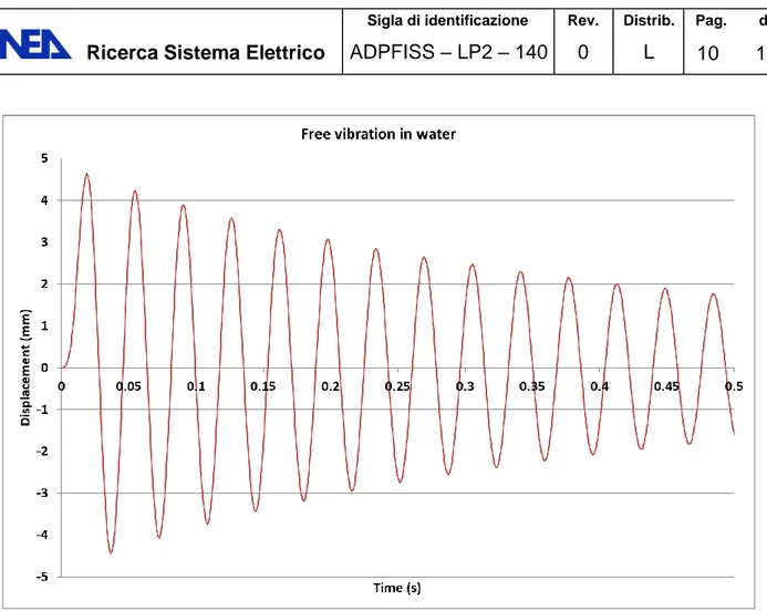
From the graph it is possible to read the new frequency: 30.3 Hz, very similar to the one computed by means of the modal analysis, as expected. It is also possible to compute the damping due to the presence of the fluid around the pin. In this case the vibration doesn’t reduce significantly its amplitude during the time considered in the numerical analysis. This means that the dumping introduced by the presence of the air is, as expected, negligible. The analysis is repeated considering the pin immersed in water and the results are reported in the Figure 12 below.
Figure 12. Pin displacement during free vibration in water.
The frequency computed is now reduced to 27.8 Hz and a 1% damping appears: these values indicate that the influence of the water is well visible, being the water density much higher than that of air.
These investigative results confirm that the Finite Element Model and the co-simulation technique are able to represent the dynamic behavior of the pin, thereby permitting to move to more realistic conditions for the successive studies.
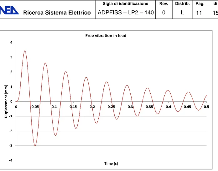
The last analysis reproduces the real condition of the pin immersed in liquid lead at 440°C (which is the average coolant temperature in the reactor). The results are shown in Figure 13 below.
The effect of lead, due to its high density, are much more pronounced than in the previous cases: the new frequency computed is 18.5 Hz, almost half the first modal frequency, while the well visible dumping, using the logarithmic decrement method, is estimated to be 2.8%.
Figure 13. Pin displacement during free vibration in lead.
5. Dynamic analysis of a group of pins immersed in fluid
As a further step in the validation of the simulation model and tool, the influence of the surrounding pins on the vibration of a single pin is studied. In order to investigate this problem a group of seven pins was modelled and implemented in the code (left and right frames of Figure 14).
The portion of fluid considered for this case study has the same shape of the wrapper enclosing the bundle [2]. The boundary conditions imposed to the fluid consider the wrapper as rigid body (Figure 15).
As for the cases discussed in the previous section, an acceleration impulse is applied only to the central pin, which starts moving. The movement is transmitted by the fluid to the adjacent pins and vice versa.
1 2 3 4 5 6
Figure 14. FE model of the pins group (left) and model of the pins group (right).
Figure 15. Portion of fluid surrounding the pin group.
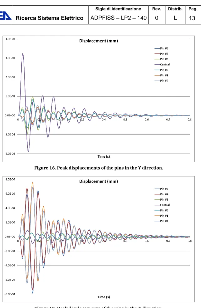
The results are shown in Figure 16 and Figure 17. In the first graph, the vertical displacement (Y axis as of Figure 14) versus time, for the point where it is larger, is reported for each pin. It is worth noting that the pins 1, 2, 4 and 5 are in counter-phase while the pins 3 and 6 are in phase with the central pin. In the graph of Figure 17 the horizontal displacement (X axis as of Figure 14) is shown; in this case pins 2 and 5 are in phase with the central pin while pins 1, 3, 4 and 6 are in counter-phase.
Figure 16. Peak displacements of the pins in the Y direction.
Figure 17. Peak displacements of the pins in the X direction.
In the picture below (Figure 18) it is shown the movements of all the pins surrounding the central one. It is worth noting that, while the pins 3 and 6 move practically along the Y axis, pushed by the fluid displaced by the central pin, the pins 1, 2, 4 and 5 move along a diagonal direction. These are exactly the expected results and this is a further confirmation that the model is able to simulate the dynamic behavior of the group of pins.
Figure 18. Combination of displacements in the X and Y directions.
Using this model it is also possible to investigate the possibility of having contact between the pins and, if the contact happens, it also possible to compute the contact pressure. In the picture below an example of possible contact is shown.
6. Conclusion and next step
This report must be considered, basically, as preparatory to further analysis to be performed on the fuel element.
Several cases were studied, in which different, progressively complicated, situations have been investigated. Starting from a modal analysis, for which a single pin – isolated for everything else – was considered, one after the other the assumptions were removed. This approach permitted to preserve the capability for expert’s judgment on the validity of the results while moving towards less obvious situations, more and more representative of the real condition of the bundle of fuel pins immersed in flowing lead and enclosed by a wrapper tube.
This work has demonstrated that the co-simulation technique provided by Abaqus is able to numerically simulate the behavior of the pins immersed in liquid lead, subjected to a dynamic load. This provides the aimed confidence on the viability of investigating the effects of flow-induced vibrations by means of Abaqus, hence to substantiate the design of the support system for the bundle of ALFRED pins.
In the next steps, the entire 127 pin bundle and the fluid inside the wrapper will be modeled as requested, and parametric analyses will be performed to drive both the design of the spacer grids and their optimal positioning (number/locations).
References
[1] ABAQUS UNIFIED FEA. SIMULIA. 166 Valley Street. Providence. RI 02909 USA. www.simulia.com
[2] G. Grasso, F. Lodi, M. Sarotto. The current ALFRED core design. Technical Report SICNUC-P000-017 rev. 0, ENEA (2017).
![Figure 1 – Schematic view of the ALFRED fuel pin (not in scale). The description of the pin reported below is extracted from [2]](https://thumb-eu.123doks.com/thumbv2/123dokorg/5607528.68006/4.892.148.748.274.437/figure-schematic-view-alfred-scale-description-reported-extracted.webp)
![Figure 4 - 3D view (cross-cut) of the fuel pellet (quotes in [mm]).](https://thumb-eu.123doks.com/thumbv2/123dokorg/5607528.68006/5.892.352.533.574.805/figure-d-view-cross-cut-fuel-pellet-quotes.webp)

![Table 1. Natural frequencies computed by modal analysis Mode Frequency [Hz] 1 30.0 2 30.0 3 83.5 4 83.5 5 164 6 164 7 221 8 221](https://thumb-eu.123doks.com/thumbv2/123dokorg/5607528.68006/7.892.121.779.220.1126/table-natural-frequencies-computed-modal-analysis-mode-frequency.webp)