2018
Publication Year
2020-11-17T16:42:06Z
Acceptance in OA@INAF
ASTRI SST-2M: the design evolution from the prototype to the array telescope
Title
Marchiori, G.; Busatta, A.; Marcuzzi, E.; Manfrin, C.; Folla, I.; et al.
Authors
10.1117/12.2313794
DOI
http://hdl.handle.net/20.500.12386/28392
Handle
PROCEEDINGS OF SPIE
Series
10700
Number
PROCEEDINGS OF SPIE
SPIEDigitalLibrary.org/conference-proceedings-of-spie
ASTRI SST-2M: the design evolution
from the prototype to the array
telescope
G. Marchiori, A. Busatta, E. Marcuzzi, C. Manfrin, I.
Folla, et al.
G. Marchiori, A. Busatta, E. Marcuzzi, C. Manfrin, I. Folla, G. Pareschi, S.
Scuderi, E. Giro, R. Canestrari, G. Tosti, E. Antolini, G. Sironi, E. Cascone,
"ASTRI SST-2M: the design evolution from the prototype to the array
*[email protected]; phone +39 041 5317906; fax +39 041 5317757;
ASTRI SST-2M: THE DESIGN EVOLUTION FROM THE
PROTOTYPE TO THE ARRAY TELESCOPE
G. Marchiori*
a, A. Busatta
a, E. Marcuzzi
a, C. Manfrin
a, I. Folla
b, G. Pareschi
c, S. Scuderi
d,
E. Giro
e, R. Canestrari
c, G. Tosti
f, E. Antolini
f, G. Sironi
c, E. Cascone
g.
a
EIE Group s.r.l., via Torino 151A, Venezia, 30172, Italy (www.eie.it);
b
Galbiati Group, via Ca’ Bianca ai Pascoli 26A, Oggiono (Lc), 23848, Italy;
c
INAF-Osservatorio Astronomico di Brera – Via Bianchi, 46, Merate (Lc), 23807 Italy;
d
INAF-Osservatorio Astrofisico di Catania – Via S. Sofia 78, Catania, 95123 Italy;
e
INAF-Osservatorio Astronomico di Padova – Vicolo osservatorio 5, Padova, Italy 35122
f
Università di Perugia – Via A. Pascoli Perugia, 06123 Italy;
g
INAF-Osservatorio Astronomico di Capodimonte – Salita Moiariello. 16, Napoli, Italy 80131.
ABSTRACT
The Cherenkov Telescope Array (CTA) observatory will represent the new frontier of imaging atmospheric Cherenkov Telescope. The simultaneous use of large, medium and small telescopes (respectively LST, MST and SST) will allow to explore the astronomy related to the very high energy domain, typical of Gamma rays, with a sensitivity, angular resolution and image quality never seen before.
Within this project, ASTRI, the Italian 2 mirrors Schwarzshild-Couder configuration Small SST led by Italian National Institute of Astronomy (INAF), has moved quickly developing a 4m class telescope prototype which has been tested with results which demonstrates excellent performance as well as wide margins for further improvements.
On the basis of the experiences made on the prototype, this paper focus on the design enhancements carried out for the telescope which will be part of the Cherenkov Telescope Array.
Keywords: Gamma rays, CTA, Small Size Telescope, Schwarzschild-Couder, segmented optics.
1.
INTRODUCTION
ASTRI (Astrofisica con Specchi a Tecnologia Replicante Italiana) is a flagship project of the Italian Ministry of Education, University and Research (MIUR) and it is strictly linked to the manufacturing of the first real precursor of the CTA (Cherenkov Telescope Array) international project.
CTA plans the construction of many tens of telescopes for Gamma Ray observation, divided in three configurations, in order to cover the energy range from a tens of GeV (Large Size Telescope, LST), to a tens of TeV (Medium Size Telescope, MST), and up to 100 TeV (SST).
Within this framework, GEC (consortium between Galbiati Group and EIE Group) has in charge the manufacturing of the ASTRI CTA small-size telescope prototypes, whose mount exploits the classical altitude-azimuth configuration, with a dual-mirror Schwarzschild-Couder optical design. The proposed telescope layout is fully compliant with the CTA requirements for the SST array. The telescope design is compact, with a 4.3 m diameter segmented primary mirror, a 1.8 m diameter monolithic secondary mirror and a primary-to-secondary distance of 3 m. The major parts of each telescope are the mount, composed by the base and the fork, and the optical supporting structure, which includes the primary mirror and secondary mirror supports.
2.
COMPARISON BETWEEN PROTOTYPE AND NEW CONCEPT
The prototype installed at Serra La Nave located in Sicily, Italy, gave the possibility to the design group to check components functionality and performance. That is a precious contribution to the creation of the telescope concept which will be used within the array of the Cherenkov telescopes.
Ground-based and Airborne Telescopes VII, edited by Heather K. Marshall, Jason Spyromilio, Proc. of SPIE Vol. 10700, 107005W · © 2018 SPIE
In particular, based on the lesson learnt from the prototype, the design was changed improving the limits seen during the use of the telescope prototype and enhancing the commonality of components in order to improve items mass production.
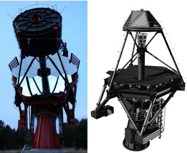
Fig 1. SST Prototype at Serra La Nave site (left) SST array telescope 3D model (right)
These changes interest especially the systems which support the optics. The M1 Dish and the M2 Back-Up Structure was profoundly revisited in order to guarantee a lighter structure with adequate stiffness. In other words, the structures were designed in order to optimize their mass and make them all collaborating to the overall telescope stiffness.
2.1 Base and Fork
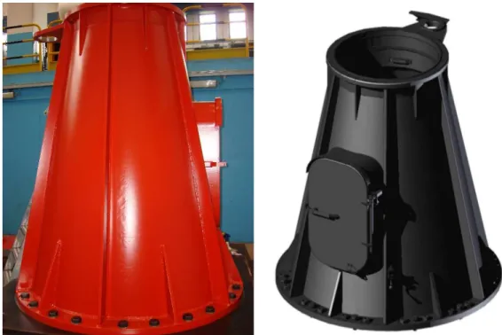
The base and fork were optimized in order to be compatible to the interfaces of the new Optical Support Structure. In particular, the Base height has been reduced in order to have the best stiffness response; however, the concept is exactly the same of the one implemented in the telescope prototype since the access door, the Azimuth bearing and encoder systems demonstrated their full functionality and adequate performance.
f+7'-, i
Fig 2. SST Prototype base (left) SST array telescope base (right)
The Fork concept was simplified, especially under a manufacturability point of view; the shapes have less slope surfaces to ease steel sheets positioning before welding. The position of the sub-systems remains approximately the same as the prototype one, except for the Elevation stow pin and limit switches. The Elevation stow pin provides parking position at 0 degrees only as all maintenance activities can be performed in that position; this is safer as there are no potential risks related to motion of the telescope during maintenance where operators can be close to it.
Fig 3. SST Prototype fork (left) SST array telescope fork (right)
2.2 M1 Dish
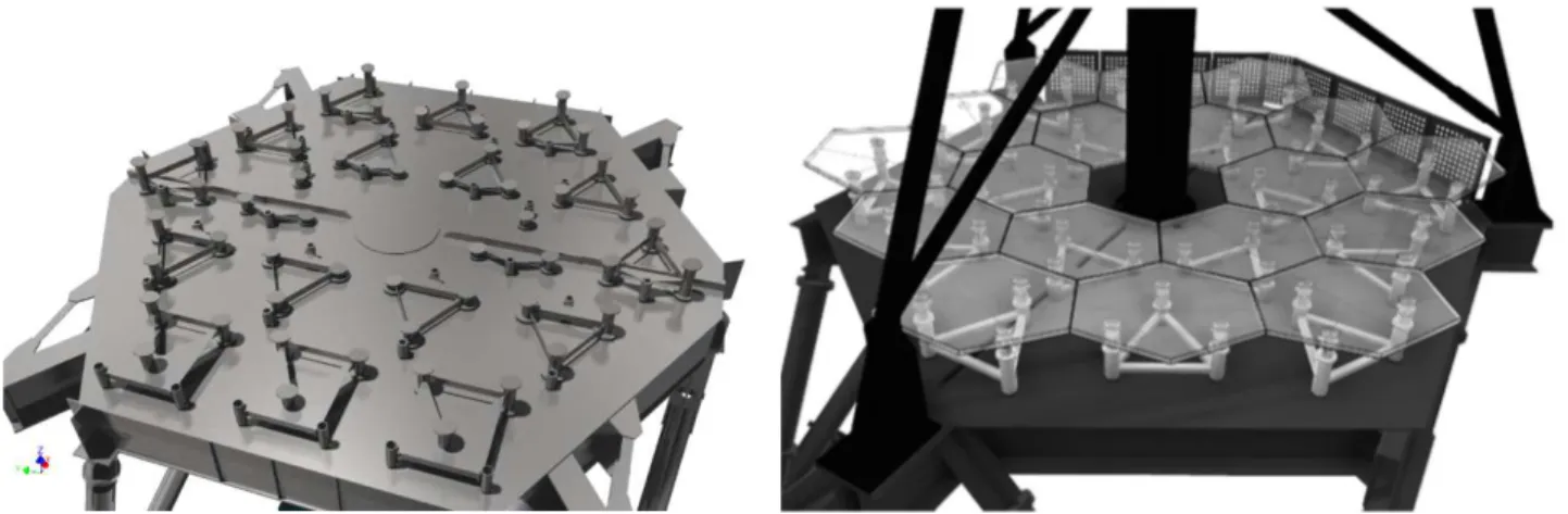
M1 Dish has changed drastically in its way to support the M1 segments systems: the layout now, follows a cylindrical symmetry, while in the prototype, the position was based on Cartesian coordinates. This brings to a complete modularity of the segment supports which are reduced to only 3 types compared to the 18 types had before.
T
Fig 4. M1 segment supports layout for prototype (left) and array telescope (right)
The structure shape of the M1 Dish is derived from the concept to provide the highest stiffness for the segments of primary mirror; the best compromise was reachable by rotating the M1 Dish structure of an angle equal to 30 degrees. It must be said that, the structure for the prototype was built with welded steel sheets while where possible, the array telescope one will be constructed with standard C profiles which reduce costs and speed up manufacturing processes. These aspects linked to the feasibility entails significant mass reduction with performance improvement implication as well as a better cost.
Another important change is the support for the OSS upper structure which is composed by three mast instead of four. This choice was done to permit a better accessibility around the primary mirror.
Fig 5. Prototype OSS upper structure (left) and array telescope OSS upper structure (right)
Finally, to connect the mast upper end all together there is a top ring that has the function to keep permanently in proper position the structure when the M2 BUS is removed for the M2 substitution.
2.3 M1 support system
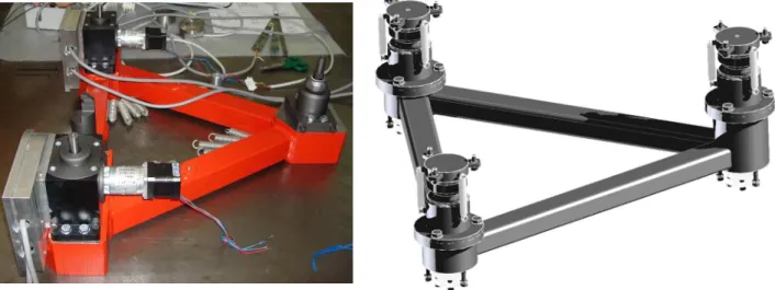
The prototype M1 segment supports were provided with actuators that could be adjusted to optimize the observations data. The tests campaign highlighted that the structure is stiff and stable enough to not have to use any type of correction on the
41
primary mirror. Following this logic, actuators are passive but they can be calibrated adequately with special tools. It is foreseen that, in the worst case, these actuators will be calibrated once per year.
Fig 6. M1 segment supports for prototype (left) and array telescope (right)
The segment support mechanisms are more compact with respect to the prototype one and this allows to have the mirror segments closer to the M1 Dish as well as the secondary mirror. This moves the center of gravity slightly down with evident advantages related to the mass of the counterweights for the Elevation axis.
2.4 M2 BUS
The structural item dedicated to the support of the secondary mirror has deeply changed by virtue of the different geometry of the OSS upper structure. This changes simplified greatly the manufacturing process and at the same time, reduced the overall mass of M2 area.
The decrease of mass of M2 systems, brings to a lighter counterweight system which had big impact, in the prototype, on the structure Eigen-frequencies.
Fig 7. M2 BUS for prototype (left) and for array telescope (centre and right)
As can be seen in the previous figure, the shape has been tailored with the content so that, the removal of a shield permits a better accessibility to the systems located inside the M2 BUS.
2.5 M2 support system
The concept of M2 supports remains the same, except for the accessibility and the maintainability aspects which have been developed in order to not oblige to dismount the M2 BUS from the telescope, as it was necessary for the prototype; the only maintenance operation that needs to be done with the removal of M2 BUS is the secondary mirror replacement. In this way, maintenance operations can be extremely faster without big expenses of time and personnel.
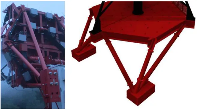
2.6 Counterweights
The improvements on the M1 and M2 supports, brought to an overall decrease of balancing torque; for this reason, it is possible to state that the overall telescope mass has been reduced of about 5 metric tons (17tons versus 22tons of the prototype) with benefits that can be seen in the drive power consumption, structural Eigen-frequencies etc.
The structures that support the counterweights have been changed in order to obtain angled beams only “in-plane” to avoid 3D angles which complicate manufacturing.
Fig 8. M2 BUS for prototype (left) and for array telescope (centre and right)
3.
STRUCTURAL PERFORMANCE
The comparison between structural behavior can be resumed by the first three Eigen-modes for the prototype and for the array telescope. Here are presented some figures of the Eigen-modes for the prototype and for the array telescope.
3.85Hz 4.56Hz 7.32Hz
4.59Hz 6.51Hz 6.99Hz
Fig 10. Eigen-modes of the array telescope at EL=90deg
Obviously, it is important to analyse different Elevation angle position in order to verify the homogeneity of stiffness in all configurations.
PROTOTYPE
TELESCOPE Eigen-modes [Hz]
Elevation angle 1st 2nd 3rd
0° 3.85 4.56 7.32 Twist around Z Tilt around X Tilt around Y 30° 4.39 5.57 7.23
Twist around Z Tilt around X Tilt around Y 60° 5.02 6.10 6.40
Twist around Z Tilt around X Tilt around Y 90° 4.58 6.34 6.76
Twist around Z Tilt around X Tilt around Y ARRAY
TELESCOPE Eigen-modes [Hz]
Elevation angle 1st 2nd 3rd
0° 3.80 5.52 6.57
Twist around Z Tilt around X M2 BUS torsion around Z 20° 3.95 6.21 6.61
Twist around Z Tilt around X M2 BUS torsion around Z 60° 4.67 6.62 6.96
Twist around Z M2 BUS torsion around Z Counterweights beams flexion 90° 4.59 6.51 6.99
Twist around Z M2 BUS torsion around Z Counterweights beams flexion The data outlined here, permit to state the followings:
- The array telescope first Eigen-modes has frequencies that are similar in value to the prototype telescope. - The array telescope has a better behaviour on the tilt around X with respect to the prototype.
- It is visible that the tilt around Y involves the counterweights only in the array telescope, while in the prototype M2 BUS is involved more profoundly.
- The prototype has a better behaviour for the twist of the M2 BUS.
These aspects are an implication related to the lighter structure and the change of the M2 BUS from four to three supports. It must be said that, the final results represent the outcome of a fine adjustment of “shape” in order to put all structural
WINO VEL TIME HISTORY
50 100 150
Time Is]
200 250 300
WIND POWER SPECTRUM DENSITY
oz
Frequency (Hz)
D: EL Free Y
Total Deformation Type: Total Deformation Frequency 10.5 Hz Sweeping Phase: O. ° Unit m 6.8819e -5 Max 6.1172e 5 53526e-5 4.5879e -5 3.8233e -5 3.0586e -5 2.294e -5 1.5293e 5 7.6465e 6 0 Min C: AZ Free Total Deformation Type: Total Deformation Frequency 8.2 Hz Sweeping Phase. 0. ° Unit or 5.5801e -9 Man 4.96010 -9 4.3401e -9 3.7201e -9 3.1001e 2.4801e 9 1.86e -9 1.24e -9 6.2001e -10 0 Min
elements in the condition to contribute to the stiffness and removing all the rest. The mass has been reduced of a 22.7% which is nearly one fourth of the prototype overall mass.
4.
SERVO ANALYSIS
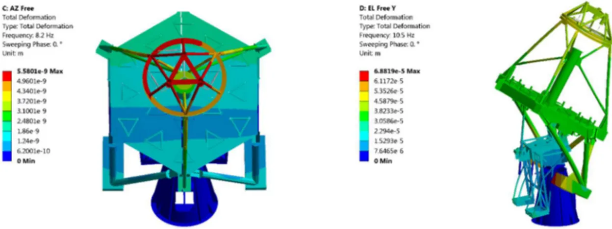
The servo analysis has considered a state space model describing the dynamic behavior of the structure obtained from the Finite Element modal analyses in “free rotor” condition up to an eigen-frequency of 100Hz. The result highlighted 74 eigen-modes which were reduced till those that are adequate to preserve the model characteristics. The analyses on the main axes transfer functions pointed out that the frequencies at 8.2Hz and the frequency at 10.5Hz were the ones with more impact on the servo tuning of respectively Azimuth and Elevation axes.
It must be noted that the frequency at 8.2Hz involves Elevation as well; this means that the motion in azimuth is slightly cross-correlated with elevation one for the presence of unbalancing on the elevation axis and the position of the elevation bearings.
Fig 11. Eigen-modes with wider effect on servo system tuning (Azimuth on left, Elevation on right)
Motors were modeled introducing cogging and ripple effects in order to have a response with the most realistic behavior. Friction was taken into account with stick-slip effect (Stribeck) which always has big impact in very slow movements such the telescopes tracking.
The wind was simulated with a history of wind based on the requirements (average wind speed 11km/h (about 3 m/s), turbulence intensity 25%, turbulence scale 50m) and on the Von Karman model.
25 EL Mewing 10 20 n ,n 50 60 w 80 Time [s] EL Pas Error loo 6 10 ]11 30 40 50 Time [[] 00 AZ Slowing 40 so 50 10 e0 50 >D ú 30-Ó E0 ç w -100 m Time [e7 AZ Slowing Error O 10 m 10 40 50 w 70 Timep7 n
Control Loops Architecture
Pos
Measured Vel
Vel Measured
The control loops architecture is the same for both the main axes.
Fig 13. Azimuth and elevation control loops architecture
For both axes the position control loop consists of a feedforward action and a PID controller:
• in the feedforward loop the command is differentiated and forwarded to the velocity loop input as a velocity command,
• the disturbance rejection properties are given by the PID controllers of the closed loops on velocity and position, The controllers of both the axes are provided with PI controllers.
It must be said that wind effect is mainly counteracted by the frictions, especially for what regard the Azimuth axis; so, for wind average speed equal or lower than 11km/h, the impacts are not remarkable.
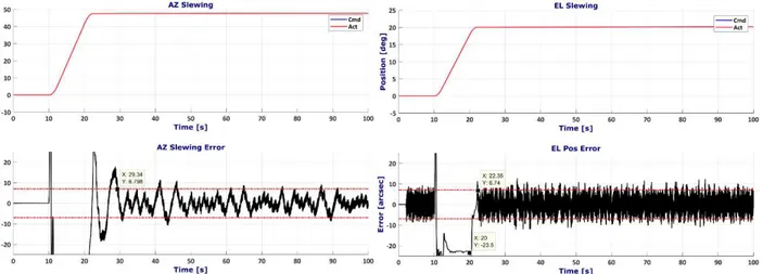
The maximum error seen by the encoders are normally lower than 3.4arcsec RMS for Azimuth and 4.8arcsec RMS for Elevation and they are similar for slewing and tracking.
Fig 14. Position error measured by the main axes encoders for a telescope slewing
5.
CONCLUSIONS
The ASTRI SST for the CTA has been designed with the extremely useful feedback from the prototype installed at Serra La Nave [1] [2]. Starting from there, the goal was to optimize the structural behavior removing all the non-structural mass; in that way, it was possible to reduce mass and consequently costs, keeping performance at the same level. In particular, the array telescope will weight 17 metric tons versus 22 tons of the prototype.
The structural and servo behavior has been deeply analyzed in order to have the confidence that, despite the mass optimization, the performance of the telescope during observation, could be comparable to the excellent responses obtained by the tests carried out on the telescope prototype. In particular, the array telescope structure seems stable and the servo dynamics demonstrates its suitability for this type of observations.
During next months, the new telescope will be built, assembled and tested; in tht way it will be possible to confirm the good results obtained by the analyses outlined here.
ACKNOWLEDGEMENTS
Galbiati Group and EIE Group, would like to express its special thanks to INAF and especially to Giovanni Pareschi and his team, for their support during entire SST re-design phase and for the experience gathered on prototype.
REFERENCES
[1] R. Canestrari, “The ASTRI SST-2M prototype for the Cherenkov Telescope Array: opto-mechanical performance”, 9906-44 SPIE2016.
[2] G. Pareschi, “The ASTRI prototype and mini-array: telescope precursors for the Cherenkov Telescope Array”, 9906-223 SPIE 2016.